Introduction
This content is an important chapter in the STM32 FreeRTOS smart home project. Through this content, you will master IoT applications based on the ESP8266 Wi-Fi module with STM32. The cloud platform used in this session is Alibaba Cloud.
This lays the foundation for subsequent hardware control through an app designed with Android Studio.
1. Introduction to ESP8266 Hardware
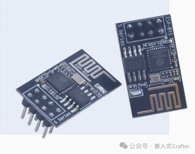
ESP8266-01S is a Wi-Fi module based on the ESP8266 chip. The following will provide a detailed introduction from its features, functions, applications, and more:
1.1. Features
- Compact Size: With a compact design, it is suitable for applications with limited space, making it easy to integrate into various small devices.
- Low Cost: Relatively low price effectively reduces the development costs of IoT devices and embedded systems, making it widely used in many low-cost projects.
- Highly Integrated: Integrates Wi-Fi functionality and a processor, reducing the need for external components, lowering the complexity and cost of hardware design, while also improving system stability.
- Low Power Consumption: Features low power characteristics, supporting various low-power modes such as deep sleep mode, suitable for battery-powered devices, extending device battery life.
- Easy to Use: Many development resources and example codes are available, allowing configuration and control via serial communication using AT commands, facilitating quick onboarding and application development for developers.
1.2. Functions
- Wi-Fi Functionality: Supports 802.11b/g/n standards, operates in the 2.4GHz band, enabling device connection to wireless networks and providing stable wireless data transmission.
- Multiple Operating Modes: Supports Station (client), AP (access point), and Station+AP coexistence modes, allowing users to flexibly configure according to actual needs, achieving interconnectivity between devices and connection to external networks.
- TCP/IP Protocol Stack: Built-in complete TCP/IP protocol stack, supporting various network protocols such as HTTP, TCP, UDP, DNS, etc., facilitating data exchange between devices and servers or other network devices.
- Serial Communication: Provides a simple UART serial interface, with a default baud rate of 115200bps, allowing easy communication with other microcontrollers or devices for data transmission and command interaction.
- GPIO Interface: Equipped with general-purpose input/output pins, which can be used to connect external sensors, actuators, and other devices, enabling control of external devices and data collection, expanding device functionality.
1.3. Hardware Resources
- Processor: The core processor ESP8266 integrates the industry-leading Tensilica L106 ultra-low power 32-bit microcontroller, with a 16-bit RISC architecture, supporting clock speeds of 80MHz and 160MHz, and supporting RTOS, meeting the processing needs of most IoT applications.
- Storage: Equipped with 1MB of Flash memory, which can be used to store program code, configuration information, and data, providing sufficient space for application development and operation.
- Power Management: Features a comprehensive power management system, supporting multiple power modes, capable of automatically switching power modes based on the device’s operating state, reducing power consumption.
1.4. Application Fields
- Smart Home: Can be used to connect various smart appliances, sensors, and controllers, enabling remote control of appliances, automated scene linkage, and environmental monitoring functions, such as smart lighting control, smart curtain control, smart locks, etc.
- Smart Office: Applied to the networking control of office devices, such as smart printers, smart projectors, etc., enabling remote management and operation of devices, improving office efficiency.
- Environmental Monitoring: Connects temperature and humidity sensors, air quality sensors, water quality sensors, etc., uploading collected environmental data to the cloud or server via Wi-Fi, achieving real-time monitoring and early warning of environmental parameters.
- Industrial Automation: In the field of industrial control, it can be used to connect industrial equipment, sensors, and actuators, enabling remote monitoring, data collection, and analysis of devices, improving the automation and intelligence level of industrial production.
- Smart Agriculture: Used in agricultural production for environmental monitoring, irrigation control, pest monitoring, etc., helping farmers achieve precision agriculture and improve agricultural production efficiency and quality.
- Education and Research: As a teaching and research tool, it helps students and researchers learn and practice IoT technology, wireless communication technology, etc., developing various IoT application projects.
1.5. Wiring Method for Microcontroller or TTL
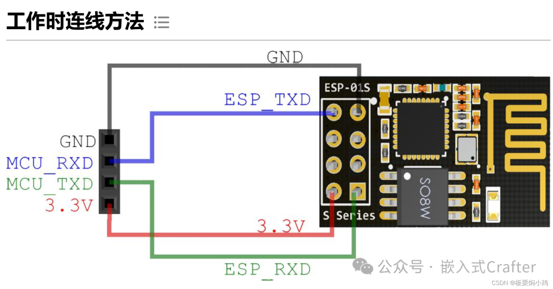
The Wi-Fi module used in this project is the ESP8266-01S, and the wiring method is as follows: Note the wiring of TXD and RXD; often, when the module is connected, there is no response due to incorrect hardware connections. It is particularly important to cross-connect the TXD and RXD of the microcontroller with the TXD and RXD of the ESP8266.
|
STM32/USBTTL |
ESP8266 |
|
GND |
GND |
|
3.3V |
3.3V |
|
TXD |
RXD |
|
RXD |
TXD |
2. Software Design
2.1. Programming MQTT Firmware
The MQTT firmware for the ESP8266-01S and the programming software can be downloaded from the link below:
Link:https://pan.baidu.com/s/1f5cNlNCMdW22GDBMksK59w?pwd=76kn
Extraction Code: 76kn
— Shared by Baidu Cloud Super Member V5
2.1.1. Ordinary Serial TTL Module
A serial TTL module is required, and the hardware connection is as follows. When I was programming the firmware, the ESP8266 always displayed waiting for power synchronization and could not program the firmware normally. After researching and trying, I connected the ESP8266’s 3V3 and EN to the 3V3 of the serial TTL module, and GND and IO0 pins were connected to GND together. For those who do not know how to do this, you can refer to the images below to modify the Dupont wires accordingly.
|
TTL Module |
ESP8266 |
|
3V3 |
3V3 and EN |
|
GND |
GND and IO0 |
|
TXD |
RXD |
|
RXD |
TXD |
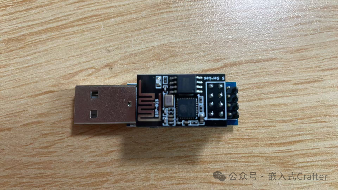
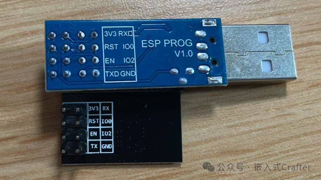
2.1.2. Dedicated Programming TTL Module
2.1.3. Download Process
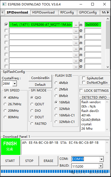
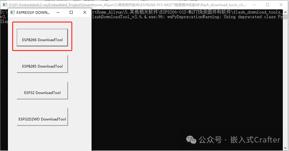
After opening the ESPFlashDownloadTool, select the first box ESP8266 DownloadTool.
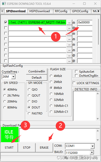
Click the first line…, select the MQTT firmware, and program it to the ESP8266 at address 0x00000, checking the box in front.
First, successfully ERASE, then click Start to program the firmware.
If you encounter issues with the program not downloading, you may need to ground the RST during the download process for 1-2 seconds and then let it float.
Wait for the display to show FINISH, indicating that the MQTT firmware download was successful.