Why can the same smartphone connect successfully with some devices but fail with others? Why can the same device connect with some smartphones but not with others? Why does the same smartphone connect quickly with the same device at times and slowly at others? What is a Master? What is a Slave? What are Connection Events and Slave Latency? This article aims to help you answer these questions.
BLE Connection Example
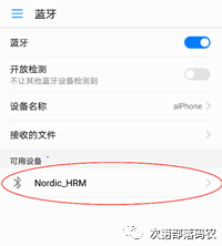
Assuming we have a smartphone A (using an Android phone as an example) and a device B (device name: Nordic_HRM), as shown below, we can connect the two via the Bluetooth interface in the Android settings menu.
-
Open the Android settings menu
-
Select the “Bluetooth” entry
-
Turn on Bluetooth
-
Wait for the system to search for results; if all goes well, the device “Nordic_HRM” will appear in the results list
-
Click “Nordic_HRM”; the phone will establish a connection with this device
This is the intuitive “connection” we experience. So, what specific processes are involved in establishing a connection between smartphone A and device Nordic_HRM? Why can they connect successfully? Let’s explain it step by step.
Broadcasting
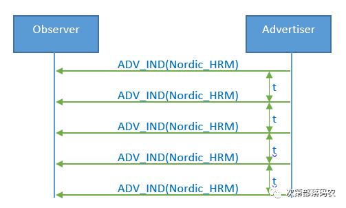
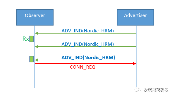
Before smartphone A (Observer) establishes a connection with device B, device B needs to broadcast first, meaning device B (Advertiser) continuously sends the following broadcast signals, where t is the broadcast interval. Each time a broadcast packet is sent, it is referred to as a broadcast event, thus t is also called the broadcast event interval. Although the broadcast event is represented by a line in the diagram, in reality, it has a duration, and the Bluetooth chip only turns on the RF module during the broadcast event. During this time, power consumption is relatively high; during the rest of the time, the Bluetooth chip remains in an idle state, resulting in very low average power consumption. For instance, with the Nordic nRF52810, broadcasting once per second results in an average power consumption of less than 11uA.
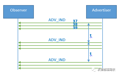
The above is just a general illustration. According to the Bluetooth specification, each broadcast event actually consists of three broadcast packets, which broadcast the same information simultaneously on three RF channels: 37, 38, and 39. Thus, the actual broadcast event looks like the following.
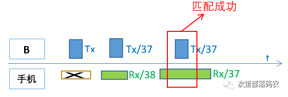
Device B continuously sends broadcast signals to the smartphone (Observer). If the smartphone does not turn on the scanning window, it will not receive the broadcast from device B. As shown in the following diagram, not only must the smartphone open its RF receiving window, but the RF receiving window of the smartphone must also successfully match the broadcast transmission window, and the broadcast RF channel and the smartphone scanning RF channel must be the same channel for the smartphone to receive device B’s broadcast signal. In other words, if device B broadcasts on channel 37 while the smartphone scans channel 38, even if their RF windows match, they still cannot communicate. Since this successful matching is a probabilistic event, the smartphone scanning for device B is also a probabilistic event. This means that sometimes the smartphone can quickly scan device B, needing only one broadcast event, while at other times it may take a long time to scan device B, needing 10 broadcast events or even more.
Connection Establishment
According to the Bluetooth specification, after the advertiser sends a broadcast packet, it must open an RF Rx window for a period of time, specifically 150us (T_IFS), to receive data packets from the observer. The observer can then send a connection request to the advertiser during this time. As shown in the diagram, the smartphone scanned device B during the third broadcast event and sent a connection request CONN_REQ (also known as CONNECT_IND).
The interaction process shown in the diagram is quite rough, so we introduce the next diagram to detail the connection establishment process.
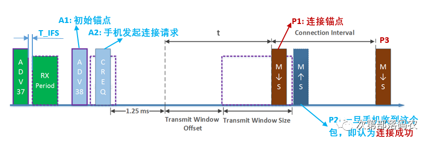
Figure 5: Connection Establishment Process
Note: In the diagram, M represents the smartphone, S represents device B, M->S indicates that the smartphone sends a data packet to device B, meaning the smartphone opens its Tx window, and device B opens its Rx window; S->M indicates the opposite, meaning device B sends a data packet to the smartphone, meaning device B opens its Tx window, and the smartphone opens its Rx window.
As shown in the diagram, after receiving the A1 broadcast packet ADV_IND, the smartphone uses this as the initial anchor point (this anchor point is not the connection anchor point), and after the T_IFS time, it sends a connection request command to the advertiser, i.e., the A2 data packet, informing the advertiser that it is about to connect and to prepare accordingly. The advertiser prepares to receive based on the connect_req command information, which contains the following key information:
-
Transmit window offset, defined as shown in Figure 5
-
Transmit window size, defined as shown in Figure 5
-
The complete definition of the connect_req data packet is as follows:
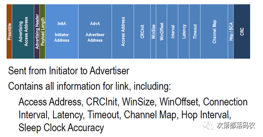
The connect_req actually informs the advertiser that the smartphone will send the first synchronization packet (P1) during the Transmit Window; thus, the advertiser should keep its RF receiving window open during this time. After device B receives P1, it will reply to the smartphone with data packet P2 (ACK packet) after T_IFS time. Once the smartphone receives data packet P2, the connection is considered successfully established. Of course, the actual situation may be more complex; the smartphone might not receive P2. In this case, the smartphone will continue to send synchronization packets until the supervision timeout is reached; during this period, as long as device B replies with an ACK packet once, the connection is considered successful. Therefore, once the P1 packet is sent, the host (smartphone) considers the connection successful, regardless of whether the device’s ACK packet has been received. This is why applications on Android or iOS systems frequently receive connection success callback events (this callback event is based on whether the P1 packet has been sent; as long as the P1 packet is sent, the smartphone considers the connection successful, regardless of whether the device’s ACK packet has been received), but in reality, the smartphone and device have not successfully established a connection. Subsequently, the smartphone will periodically send data packets (Packet) to device B using P1 as the anchor point (origin), with the Connection Interval as the cycle. The Packet serves not only for data transmission but also has two very important functions:
-
Synchronizing the clocks of the smartphone and device; that is, every time the device receives a packet sent by the smartphone, it will reset its timing origin to synchronize with the smartphone.
-
Informing the device that it can now send data to the smartphone. After the connection is established, BLE communication will switch to a master-slave mode, thus referring to the connection initiator (smartphone) as Master or Central and the connected device (previously the Advertiser) as Slave or Peripheral. The reason BLE communication is in master-slave mode is that the Slave cannot arbitrarily send information to the Master; it must wait for the Master to send a packet before it can return its data to the Master within the specified time.
Connection Failures
There are several typical connection failure scenarios:
-
If, as shown in Figure 5, the slave does not receive the P1 sent by the master during the transmit window, the connection will fail. At this point, the issue should be investigated on the master side to determine why the master did not send out P1 at the scheduled time.
-
If the master sent P1 during the transmit window, meaning the master sent P1 according to the timing agreed in connect_req, but the slave did not send back P2 or did not send it back within the timeout period, the connection will also fail. At this point, the issue should be investigated on the slave side to see why the slave did not send back P2.
-
If the master sent P1 and the slave sent back P2, but either the host or the slave still reports a connection failure, this situation may indicate a software issue, requiring careful investigation of the master or slave software.
-
Another common connection failure scenario is excessive RF interference in the air. In this case, a clean environment, such as a shielded room, should be found to eliminate interference before testing the connection again.
Connection Events
Once the connection is successful, the master and slave must interact at the beginning of each connection interval, meaning the master sends a packet to the slave, and the slave sends a packet back to the master. This entire interaction process is referred to as a connection event or gap event. The Bluetooth chip only turns on the RF module during the connection event, resulting in higher power consumption; during the rest of the time, the Bluetooth chip remains in an idle state, resulting in very low average power consumption. For example, with the Nordic nRF52810, if the Master and Slave communicate once per second, the average power consumption is around 6 microamps. The Master cannot constantly send data to the slave, so the master mostly sends empty packets (empty packet) to the slave. Similarly, the slave does not always have data to send to the master, so the packets the slave replies to the master are mostly empty packets. Additionally, during a connection event, the master can send multiple packets to the slave to improve throughput. Thus, the communication timing diagram after a successful connection should look like this:
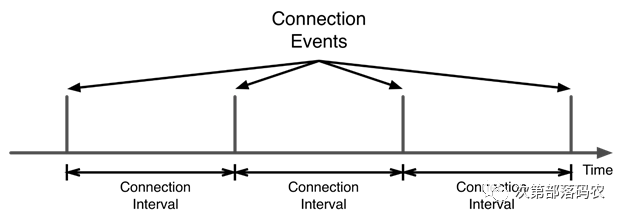
Figure 7: Communication Timing Diagram After Successful Connection (Only One Packet Sent Per Connection Event)
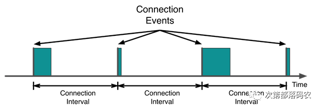
Figure 9: Communication Timing Diagram After Successful Connection (Multiple Packets May Be Sent During Connection Event)
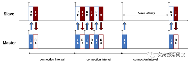
Figure 10: Details of Connection Event
Slave Latency
In Figure 10, slave latency (slave latency = 1) is mentioned; so what is slave latency?
As previously mentioned, at the start of each connection interval, the Master and Slave must interact, even if they are exchanging empty packets. However, if the slave defines slave latency, for example, slave latency = 9, the slave can respond to the master only every 9 connection intervals, meaning the slave can sleep through the first 8 connection intervals and only respond with a packet to the master in the 9th connection interval. This greatly reduces the slave’s power consumption, enhancing battery life. Of course, if the slave has data to report to the master, it can transmit it directly without waiting for the 9th connection interval, thus conserving power while improving data transmission timeliness.
Summary of GAP Layer Roles
For the smartphone and device B mentioned above, during BLE communication, their states change over time, and their relationship evolves. Therefore, the Bluetooth specification assigns different names to the smartphone and device B based on different time periods or states. The GAP layer defines the following roles:
-
Advertiser: The device that broadcasts.
-
Observer or Scanner: The device that can scan broadcasts.
-
Initiator: The device that can initiate connections.
-
Master or Central: The main device after a successful connection, i.e., the device that actively sends packets.
-
Slave or Peripheral: The subordinate device after a successful connection, i.e., the device that passively returns packets.
Figure 11 connects the observer, initiator, and central over time. In fact, these three roles are independent of each other, meaning a device can support only the observer role without supporting the initiator and central roles. Similarly, Figure 11 also connects the advertiser and peripheral, which are also independent; a device can act solely as an advertiser without supporting the peripheral role.
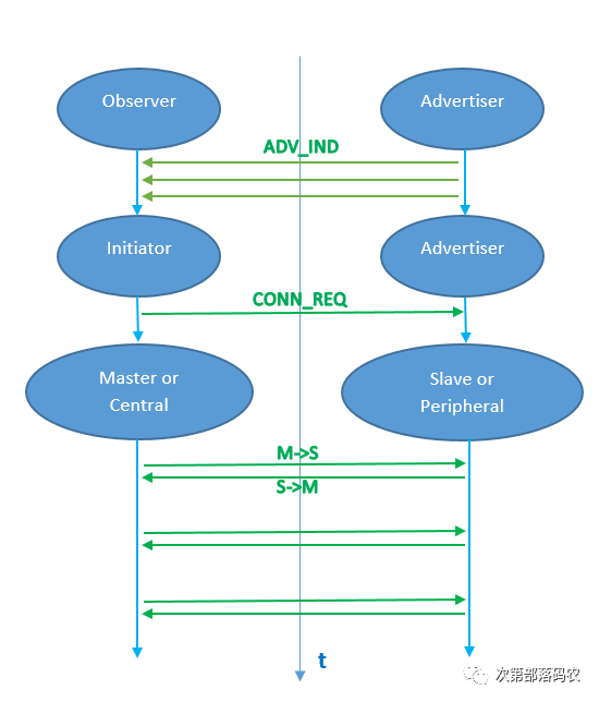
Figure 11: GAP Layer Roles