The S7-1200 CPU provides up to 6 (1214C) high-speed counters, which count independently of the CPU’s scan cycle.
The measurable single-phase pulse frequency is up to 100KHz, and for quadrature or A/B phase, it is up to 30KHz. In addition to counting, it can also be used for frequency measurement. The high-speed counter can be connected to incremental rotary encoders, and users can utilize this function by configuring the hardware and calling the relevant instruction blocks.
01High-Speed Counter Operating Modes
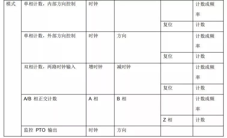
The high-speed counter is defined in 5 operating modes.
1. Counter, external direction control.
2. Single-phase counter, internal direction control.
3. Dual-phase increment/decrement counter, dual pulse input.
4. 5 A/B phase quadrature pulse input.
5. Monitor PTO output.
Each high-speed counter has two operating states.
1. External reset, no start input.
2. Internal reset, no start input.
All counters do not require startup condition settings. Once configured in the hardware wizard, they can be downloaded to the CPU to activate the high-speed counter. In A/B phase quadrature mode, 1X (1 times) and 4X (4 times) modes can be selected. The input voltage supported by the high-speed counting function is 24V DC; currently, 5V DC pulse input is not supported. Table 8-1 lists the hardware input definitions and operating modes of the high-speed counters.

Not all CPUs can use 6 high-speed counters; for example, the 1211C only has 6 integrated input points, so it can support a maximum of 4 high-speed counters (when using signal boards).
Due to different definitions for the same physical point in different modes, care must be taken when using multiple counters, as not all counters can be defined in any operating mode simultaneously.
The inputs for high-speed counters use the same addresses as regular digital inputs. Once an input point is defined as a high-speed counter input, it cannot be used for other functions. However, in certain modes, unused input points can still be used for other functions. The PTO monitoring mode is only supported by HSC1 and HSC2. In this mode, no external wiring is required, as the CPU has already made internal hardware connections, allowing direct detection of pulses generated through the PTO function.
02High-Speed Counter Addressing
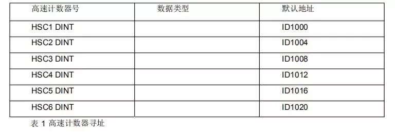
The CPU stores the measurement values of each high-speed counter in the input process image area, with a data type of 32-bit signed integer. Users can modify these storage addresses in the device configuration, and these addresses can be accessed directly in the program. However, since the process image area is affected by the scan cycle, the value will not change within a single scan cycle, while the actual value in the high-speed counter may change within that cycle. Users can read the current actual value by accessing the peripheral address. For example, the peripheral address for ID1000 is “ID1000:P”. Table 8-2 shows the high-speed counter addressing list.
 03Frequency Measurement
In addition to providing counting functions, the S7-1200 CPU also offers frequency measurement capabilities, with 3 different frequency measurement cycles: 1.0 seconds, 0.1 seconds, and 0.01 seconds. The frequency measurement cycle is defined as the time interval for calculating and returning a new frequency value. The returned frequency value is the average of all measurements from the previous measurement cycle, regardless of the selected measurement cycle. The measured frequency value is always expressed in Hz (pulses per second).
04High-Speed Counter Instruction Block
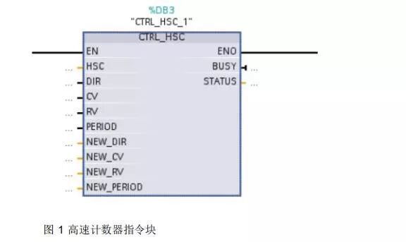
The high-speed counter instruction block requires a specified background data block for storing parameters. Figure 8-5 shows the high-speed counter instruction block.
 05Application Example
To facilitate understanding of how to use the high-speed counting function, an example is provided for configuration and application.
Assuming there is a single-phase incremental encoder as feedback on a rotating machine connected to the S7-1200 CPU, the requirement is to reset the counter after counting 25 pulses and restart counting, executing this function repeatedly.

For this application, select CPU 1214C, with the high-speed counter as: HSC1. The mode is: single-phase counting, internal direction control, no external reset. Accordingly, the pulse input should be connected to I0.0, using the preset value interrupt (CV=RV) function of HSC1 to implement this application.
Configuration Steps:
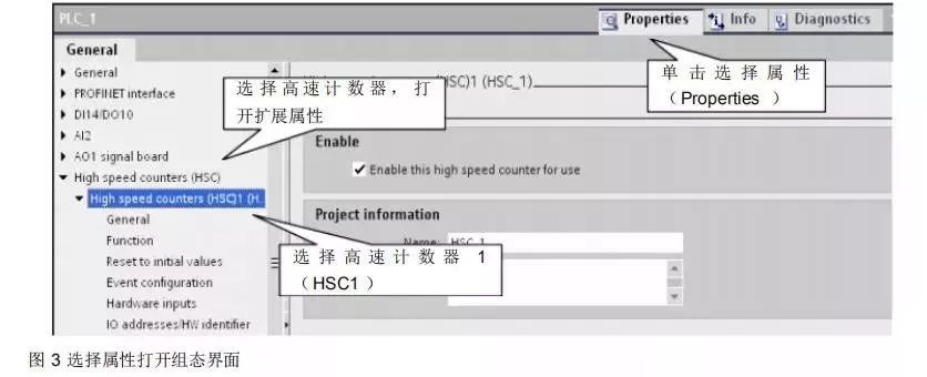
First, in the device configuration, select the CPU, click properties, activate the high-speed counter, and set the relevant parameters. This step must be executed; the high-speed counter function of the 1200 must be activated in the hardware configuration before proceeding with the following steps.
Add a hardware interrupt block, associating it with the corresponding preset value interrupt generated by the high-speed counter.
In the interrupt block, add the high-speed counter instruction block, write the program to modify the preset value, set the reset counter parameters, and download the program to execute the function.
1. Hardware Configuration
Select the CPU as shown in the figure.
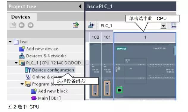
Figure 3 shows the selection of properties to open the configuration interface.
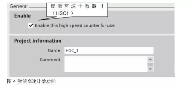
Activate the high-speed counting function as shown in Figure 4.
Configure counting type and direction as shown in Figure 5.
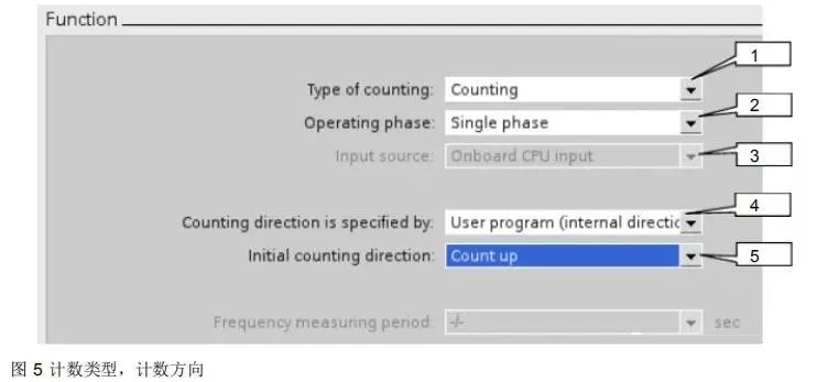
1. The counting type is divided into 3 types: Axis of motion, Frequency measurement, Counting. Here, select Counting.
2. The mode is divided into 4 types: Single phase, Two phase, AB Quadrature 1X, AB Quadrature 4X. Here, select Single phase.
3. The input source used is the CPU integrated input points.
4. Counting direction selection is set to User program (internal direction control).
5. The initial counting direction is set to Count up.
The initial value and reset configuration are shown in Figure 6.

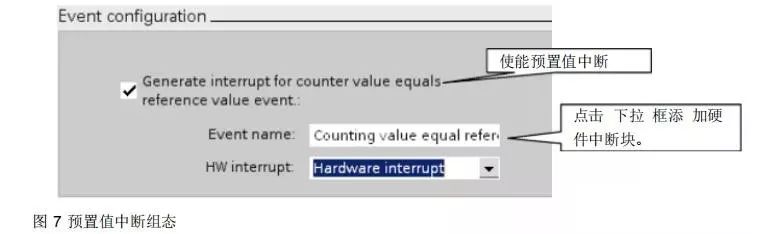
The preset value interrupt configuration is shown in Figure 7.
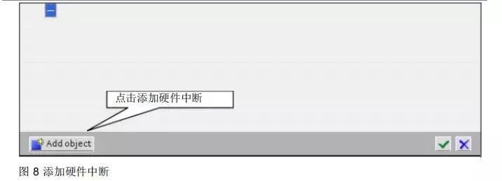
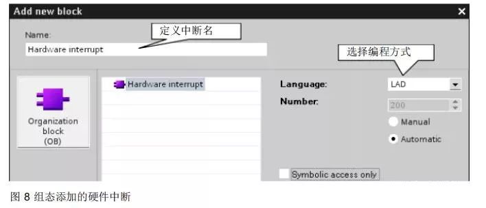
Configuration of the added hardware interrupt is shown in Figure 8.
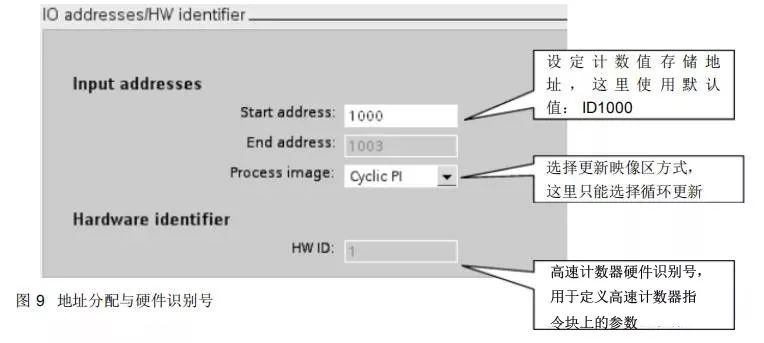
Address allocation and hardware identification number are shown in Figure 9.
At this point, the hardware configuration part is complete, and we will proceed to program writing.
2. Program Writing
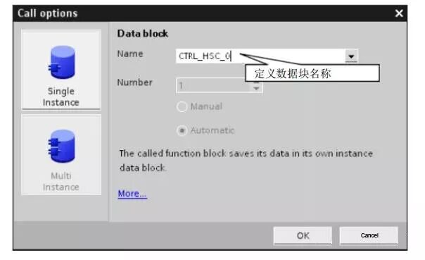
Add the high-speed counting instruction block to the hardware interrupt.
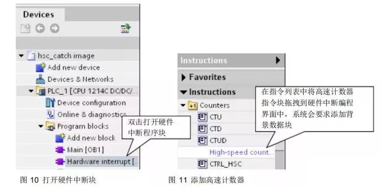
Figure 12 defines the background data block for the high-speed counter.
The program view is shown in Figure 13.
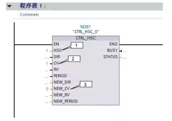
1. This is the hardware identification number specified by the system in Figure 9; here it is filled with 1.
2. “1” enables the update of the initial value.
3. “0” sets the new initial value to 0.
At this point, the program writing part is complete. After downloading the completed configuration and program to the CPU, it can be executed. The current counting value can be read from ID1000. Regarding the high-speed counter instruction block, if there is no need to modify the parameters in the hardware configuration, it does not need to be called, and the system can still count.