This article introduces how to flash the official firmware on the STM32MP157D-DK1 development board.
1. Introduction to Basic Hardware of the Development Board
1. Common Interfaces
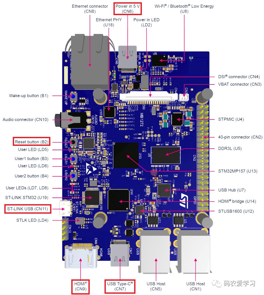
The various interfaces on the board are as follows. The main interfaces used for firmware flashing in this article include:
-
CN6: Power Supply Interface -
B2: Reset Button -
CN11: ST-LINK USB (used for serial port information viewing) -
CN9: HDMI Display Interface -
CN7: Type-C Data Flashing
2. Boot Switch
When flashing the firmware, you need to insert the MicroSD card and switch the BOOT switch on the board.
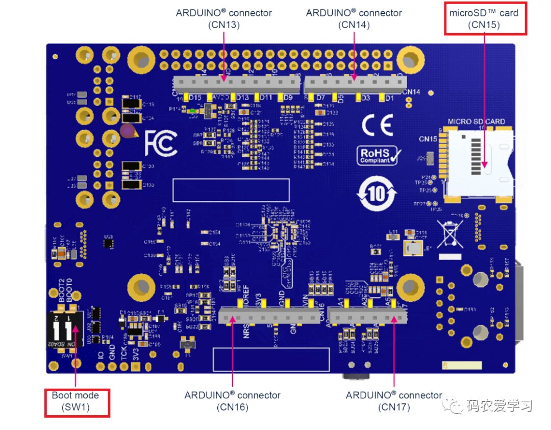
Note: The “Boot 1” on this board is connected to GND and is always 0.
| Boot mode | Boot 0 | Boot 1 | Boot 2 |
|---|---|---|---|
| USB boot for flashing firmware | 0 | 0 | 0 |
| Not supported | 1 | 0 | 0 |
| Engineering boot | 0 | 0 | 1 |
| microSD card boot | 1 | 0 | 1 |
During flashing, use the firmware flashing mode, and after flashing is complete, use the microSD card boot mode.
2. Preparation for Flashing
1. Necessary Hardware Preparation
-
Ubuntu Virtual Machine: Set up the flashing software environment -
STM32MP157D-DK1 Development Board -
Micro SD Card: Flashing to the SD card -
5V/3A Type-C Power Supply: Power supply -
Type-C Data Cable: Data cable for flashing -
Android Data Cable: Serial port for viewing flashing information -
HDMI Monitor: View the official firmware demo after flashing -
Mouse: Mouse operation during demo viewing
2. Install STM32CubeProgrammer Tool
Available for both Windows and Linux, here we introduce the installation steps in the Linux system of the Ubuntu virtual machine.
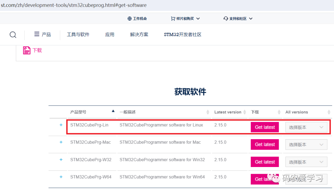
Download STM32CubeProgrammer software: https://www.st.com/en/development-tools/stm32cubeprog.html#get-software
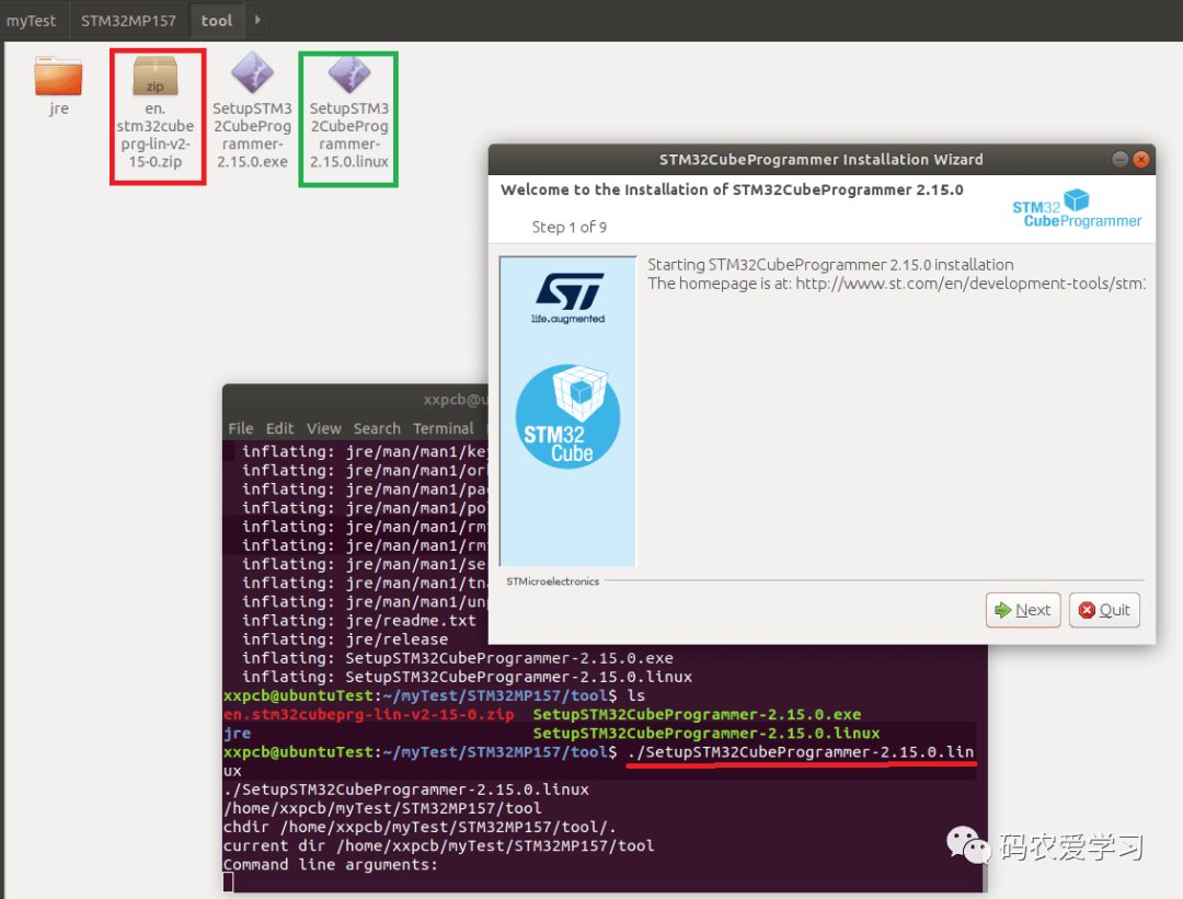
Unzip and install; after unzipping, a jre folder and two files will appear, then execute the SetupSTM32CubeProgrammer-2.15.0.linux file to install:
unzip en.stm32cubeprg-lin-v2-15-0.zip
ls
./SetupSTM32CubeProgrammer-2.15.0.linux
There will be a graphical installation prompt:
After installation, set the environment variable (this can be set temporarily when preparing for flashing):
export PATH=/home/xxpcb/myTest/STM32MP157/tool/cubeprog/bin:$PATH
3. Install USB Serial Link for Flashing
Install a driver to recognize the USB flashing interface of the development board.
Still operating in the Ubuntu virtual machine:
sudo apt-get install libusb-1.0-0
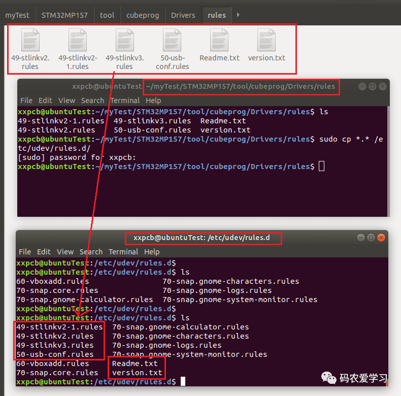
Then copy some files to /etc/udev/rules.d:
cd ~/myTest/STM32MP157/tool/cubeprog/Drivers/rules
sudo cp *.* /etc/udev/rules.d/
4. Download the Image
Download the STM32MP1 Starter Package image from https://www.st.com/en/embedded-software/stm32mp1starter.html#get-software
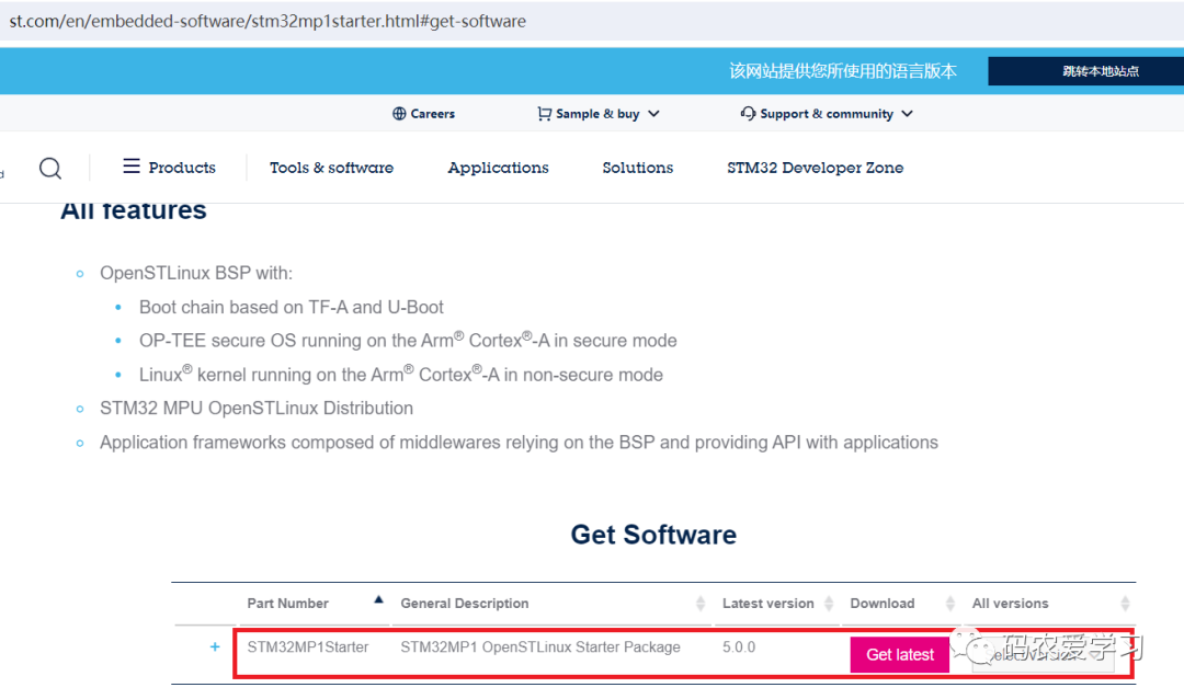
After downloading, it is named: en.flash-stm32mp1-openstlinux-6.1-yocto-mickledore-mp1-v23.06.21.tar.gz
Then copy it to Ubuntu and unzip:
cd /home/xxpcb/myTest/STM32MP157/STM32MPU-Ecosystem-v5.0.0/Starter-Package
tar xvf en.flash-stm32mp1-openstlinux-6.1-yocto-mickledore-mp1-v23.06.21.tar.gz
The binary files and Flash layout files are located in the stm32mp1-openstlinux-6.1-yocto-mickledore-mp1-v23.06.21/images/stm32mp1/ directory:
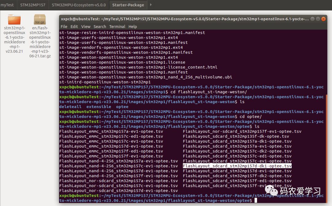
For example, the FlashLayout_sdcard_stm32mp157d-dk1-optee.tsv is needed for the STM32MP157D-DK1 development board.
3. Flashing
1. Connect the Board to the Computer
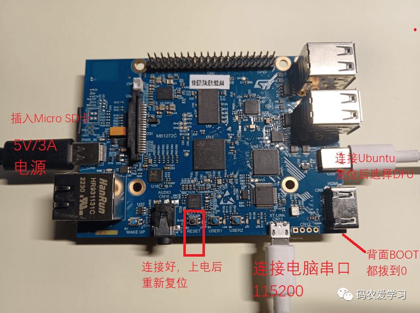
The steps are as follows:
-
Insert the SD card into the board -
Set the BOOT dip switch to 0 -
Connect the power cable (can also power on last) -
Connect the Type-C data cable and the Android data cable -
Press the reset button -
The Android data cable is used for serial port functionality, connecting to the serial port software on Windows computer to view the information -
The Type-C data cable is the flashing cable, connecting to the Ubuntu virtual machine, note it is this DFU one, as shown below

2. Command Line Flashing
Navigate to the downloaded firmware directory, reaching the stm32mp1 level:
cd ~/myTest/STM32MP157/STM32MPU-Ecosystem-v5.0.0/Starter-Package/stm32mp1-openstlinux-6.1-yocto-mickledore-mp1-v23.06.21/images/stm32mp1
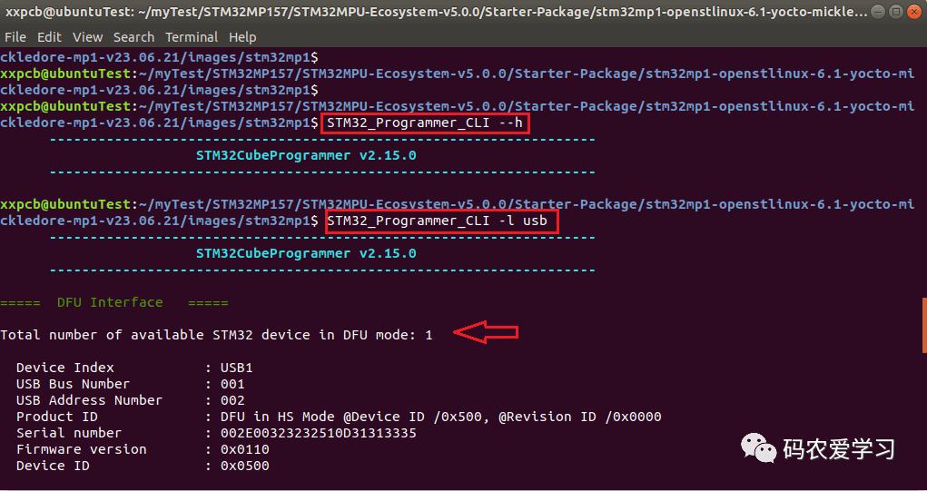
Then you can check the version of the flashing tool and the board connection information:
STM32_Programmer_CLI --h
STM32_Programmer_CLI -l usb
If it prints normally, it is functioning correctly:
Then use the following command to flash:
STM32_Programmer_CLI -c port=usb1 -w flashlayout_st-image-weston/optee/FlashLayout_sdcard_stm32mp157d-dk1-optee.tsv
The first time flashing resulted in an error message:
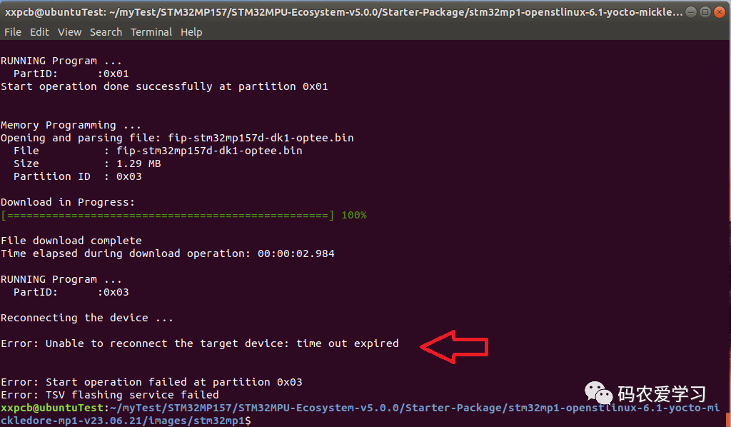
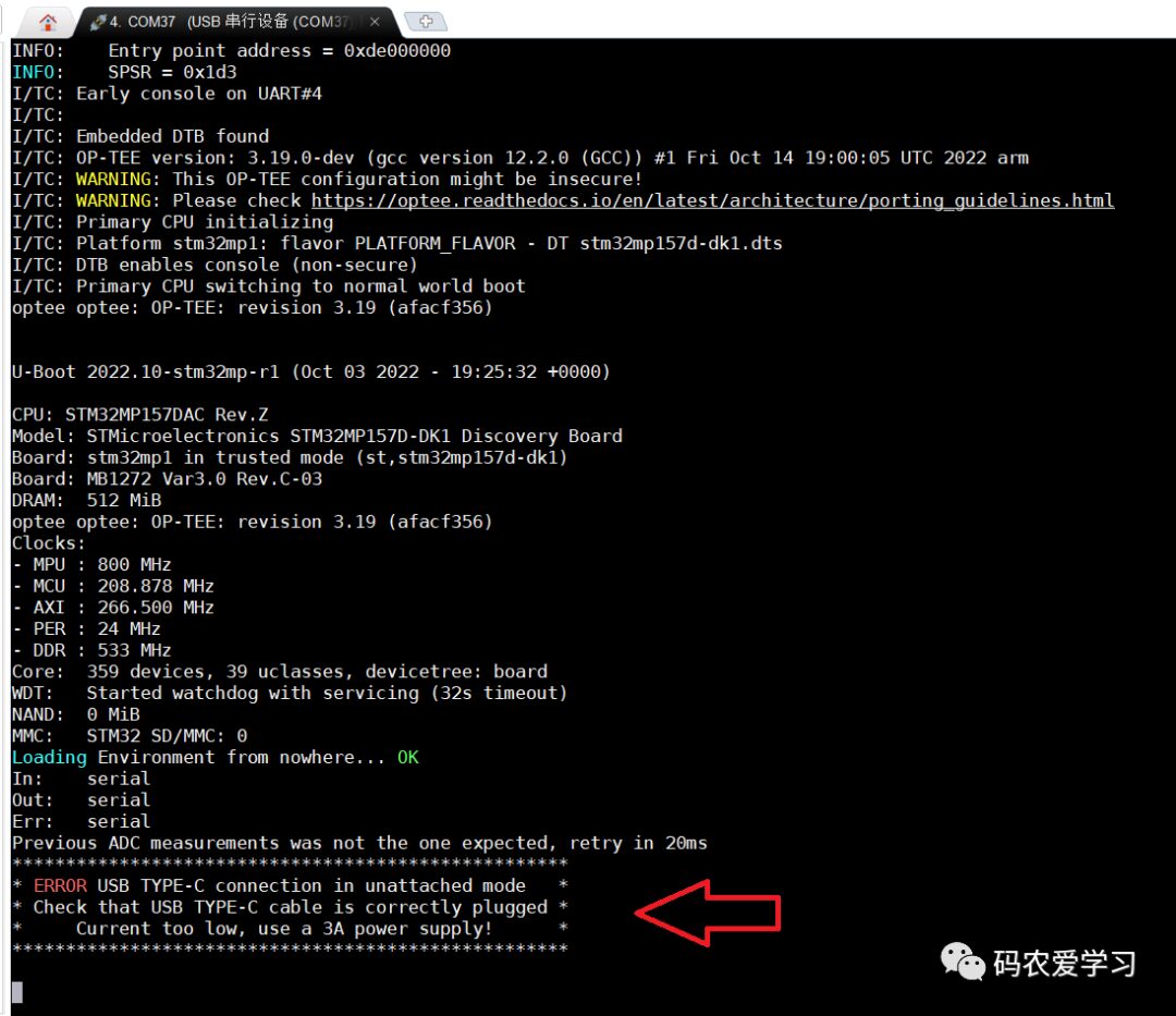
Checking the serial port output, it was found that the power supply current was insufficient (I initially used a 2A power supply):
Replacing it with a 3A power supply and re-flashing, also note that at the beginning of flashing, the board will automatically restart (reset), you need to reconnect the USB download in the virtual machine, otherwise it will still report an error.
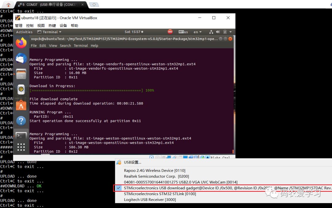
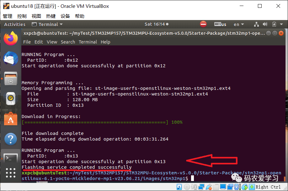
Flashing takes a few minutes, and the final successful flashing print information is as follows:
4. Demonstration
5. Summary
This article introduced the detailed process of flashing the official firmware on the STM32MP157D-DK1 development board, recording the actual operational results during the flashing process and the problems encountered along with their solutions, and finally demonstrating the effects after flashing.

END
Source: Programmer Loves Learning
Copyright belongs to the original author, if there is infringement, please contact for deletion.
▍Recommended Reading
The Operating System of the Japanese Almost Dominated the World…
Modify a few lines of code, reducing the for loop time from 3.2 seconds to 0.3 seconds
VSCode vs. SourceInsight, which is better for viewing source code?