
Click the blue text to follow us and set as:Star Mark. Quality articles delivered quickly!

Introduction
Hello everyone, I am Brother Xue. Recently, readers in the VIP member group have inquired about the design of the video intercom system.Currently, the design of the video intercom system combined with the smart home system is the latest idea, especially high-end properties will plan smart home systems. Today, I will share a design plan for the video intercom system combined with the smart home system, let’s see what functions it has?
This complete Word document is available for VIP members who need it, feel free to message me for download!
Non-members can also enter my Knowledge Planet to download it, just scan the code to enter.
If you want to download high-quality weak current materials, you can scan to join!

Eventually, we will cross the sea of growth.
01
Main Text
1.1.1 Design Purpose
The design includes the following systems: video intercom system and access control system based on video intercom, smart home system, community services, etc.
From the user’s perspective, smart homes are composed of three networks: home network (HOMENET), community management network (INTRANET), and international interconnection network (INTERNET). The full application of these three networks allows the network to enter homes, come closer to life, and reflect the true meaning of smart homes. The smart home system in households is driven by this strong demand, belonging to the home network category. It is this system that makes people feel that the network is nearby, omnipresent, allowing them to fully utilize network resources and advantages in work, study, and life, leading to an efficient, convenient, and safe life.
The video intercom system is a fully digital residential smart system based on the community Ethernet platform (TCP/IP transmission protocol). This system utilizes the Ethernet transmission platform within the community to digitally transmit all video, audio, monitoring, control, and status information. It integrates various functions such as video intercom, information release, security alarms, access control, and various rich residential environment controls, all coordinated and unified, organically merged into one.
1.1.2 Design Scope
We can provide system design, software and equipment supply installation, system installation debugging, system linkage debugging, user training, acceptance, and after-sales service for the video intercom access control system for a certain plot.
The system covers the entrances and exits of each residential building, each unit, as well as the underground parking lot and community entrances.
1.1.3 User Demand Analysis
The video intercom access control system for a certain plot needs to adopt a color touch screen, digital video intercom system, with indoor units installed in each unit, a wall-mounted unit at the community entrance, and an access control unit in the residential lobby, as well as access control for the underground parking lot.
1.1.4 Functions of the Video Intercom Access Control System
This design plan for the video intercom system is based on the MOX video intercom system and takes into account the functions of other brands.
System Functions:
1. Three-party call function
Function Overview:
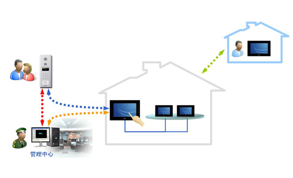
Visitor and resident communication: When a guest visits, they dial the resident’s number through the unit entrance unit, and the corresponding indoor unit emits a harmonious ringing sound while transmitting the visitor’s image to the indoor unit’s visual module. Picking up the microphone allows for communication.
Visitor, resident, and management center communication: The visitor can call the resident and management center through the entrance unit to achieve two-way intercom.
The management center can notify the resident and also call the resident’s extension through the management machine for two-way intercom; the resident can directly call the management center through the indoor unit, and the management center will display the resident’s information.
2. Access control function
Function Overview
Remote unlocking: After the visitor calls the resident, if the host needs to meet the visitor, they just need to press the door opening button on the indoor unit, and the door will automatically open. After the visitor enters, the door will automatically close; the central administrator can also remotely open the electric lock of each building entrance through the management machine.
Password unlocking: Residents can also open the community gate with a password, with 256 sets of passwords, and residents can change their passwords at any time, ensuring safety and convenience.
Induction card unlocking: Residents can use an induction card to unlock the main entrance of the building, and this induction card can participate in the apartment’s one-card system. It can adopt independent access control, networked access control, or reserved access control slots for convenience.
3. Security alarm function
Function Overview
Alarm settings: Up to 8 alarm zones, expandable; residents can directly set alarms (arming, disarming, etc.) through buttons on the indoor unit, with menu display for simplicity; alarm zone types can be set (i.e., alarm, follow-up, delay, 24-hour monitoring), adapting to different types of alarm detectors; residents can set or modify passwords (including master, guest codes, anti-hijacking codes) to make settings more professional.
Alarm information release: When an alarm occurs at the resident’s home, the indoor unit immediately transmits the alarm signal to the management center, and the management machine emits an alarm sound while displaying the resident’s room number and alarm type for timely handling by property personnel.
4. Information release function
Function Overview
Information group call: The management center can edit specific text information (such as weather forecasts, community activities, fee notifications, etc.) through information release software and send it to all residents or a specific unit (area), and all residents can receive the same information.
Designated information sending: The management center can edit specific text information (such as urging the payment of property fees, etc.) through information release software and send it to designated residents based on room number and other information.
Information inquiry: All sent information can be queried and printed through information release software.
Smart mailbox information notification: When there are new letters in the mailbox, the indoor unit can receive information prompts sent from the mailbox.
5. Image monitoring function
Function Overview
Residents can monitor the unit entrance machine or individual door machine through the indoor unit to check the situation at the door.
The management machine can monitor the situation at the unit entrance machine.
6. Image storage function
Function Overview
When the owner is not at home, if there are visitors, the system will automatically record the images of the visitors.
When the owner returns home, they can browse the images of the visitors through the indoor unit, making it very convenient to know who visited during this period for follow-up contact.
7. Inter-unit communication function
Function Overview
Indoor units between residents can communicate with each other, and the master unit can actively call the subunit, just like an internal phone, without incurring any phone charges (visual calls: optional).
For duplex structures with visual intercom subunits, the subunit can communicate directly with visitors and open the door for them, while the terminal can call the subunit and communicate with it.
8. Door status alarm function
Function Overview
The exterior of the entrance unit has protective measures to prevent abnormal disassembly, and when abnormal disassembly occurs, the alarm information will be reported to the management machine.
If the electric anti-theft door is opened for more than 120 seconds, the management machine will have sound and light alarm prompts and display the door number.
9. Software management function
Function Overview
The system uses fully software-based management, and managing with a PC has the following benefits:
Large information storage capacity. Traditional management machines are single-chip mode with limited information storage, while using a PC stores information on the computer hard disk, greatly increasing information storage capacity.
Convenient for adding and integrating system functions, all functions are modularized in software, eliminating the need to categorize management machines into several types (visual/non-visual, etc.).
Convenient for integration with other weak current systems, many weak current general contractors need to integrate the entire weak current system into IBMS. Now, only mutual software communication is required, and IBMS can easily extract the operation status and device parameters of intercom devices from our software, while traditional management machines require collecting a large number of dry nodes or simply cannot collect them.
Convenient for system upgrades and maintenance. The PC operating system adopts the most popular WINDOWS, and technical personnel can provide remote technical support. In the 900 system, remote upgrades of indoor units and other devices can also be done through software, which traditional management machines cannot achieve.
10. Interface customization function
Function Overview
The interface of the indoor unit can be customized according to customer requirements.
11. Management machine C/S architecture
Function Overview
C/S architecture: multiple management machines jointly manage IRIS devices. Among these management machines, one must have database server functionality, and all management machines synchronize data updates (such as call data, alarm data, etc.) with the database server through Ethernet, allowing mutual call transfer and collaborative work.
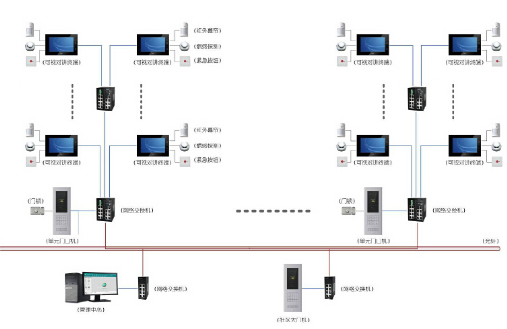
1.1.5 Video Intercom Access Control System Architecture
The system adopts a digital intercom system based on TCP/IP network transmission.
1.1.6 Smart Home System (Expandable Functions Reserved)
Humane design promotes smart homes to open a beautiful new life, as people yearn for the art of perfect living. Now, just one button is needed, and an easy life begins.
Music, lighting, cinema, screen… all elements seem to be illuminated by you, presenting an unparalleled sense of harmony. Sitting on a comfortable sofa, watching your favorite movie, or listening to your favorite music. The wall lamp’s light is just right, and the night outside is clear.
Materialism does not equal an ultimate life. Intelligence brings people an unprecedented freedom. Just a little effort, all details flow around you smoothly.
Smart homes bring the best things in the world to those who understand and deserve them. For those who advocate the perfect art of living, enter the ultimate life journey customized wholeheartedly by the editor of the house search with perfect images, pure sounds, and freely changing light and shadow.
Before structuring our smart home plan, let’s take a look at the current living scenarios of most families and their desire for intelligence:
There are many home appliances at home, including TVs, DVD players, audio systems, air conditioning, electric curtains, remote-controlled fans, etc. Each appliance has its remote control, making it cumbersome to switch between several remote controls!
Home appliances can be remotely controlled, which is indeed very convenient. If all the lights in the house could be remotely controlled, how great would that be! If you could press a button before sleeping to turn off all the lights in the house, how convenient would that be!
The living room has many background lights (downlights, spotlights, chandeliers, wall lamps, etc.), which can either be fully on or fully off. Over time, they become decorations and waste electricity! If the switching on, off, brightness, and dimness of these lights could be combined, that would be so cool! This way, there would be dining lighting effects for meals, guest lighting effects for meetings, cinema lighting effects for watching TV or DVDs, and even different lighting effects corresponding to seasonal and emotional changes, which would be thoughtful!
Using traditional hard wiring to achieve two-way switches is too complicated; not only is the wiring complex, but it cannot be resolved without a certain level of electrical skills! Smart switches can freely achieve two-way or multi-way switching, and the lights in the garage, courtyard, corridor, or stairway can automatically turn off after a few minutes of being turned on.
When you are watching TV and the phone rings, you have to fumble to lower the TV volume when answering the phone. How great would it be if the TV volume could automatically lower when you pick up the phone and return to its original volume when you hang up!
Whole-house background music sharing is currently a hot topic in home decoration. Every room in the house (including the kitchen and bathroom) can independently listen to music, listen to radio broadcasts, freely switch audio sources, and adjust the volume without interference.
Burglars breaking in, gas leaks, and house fires are safety hazards at home. If there can be timely alerts and automatic calls to report emergencies when something goes wrong at home, that would be great! If family members encounter coercion or emergencies, pressing a button can automatically dial the phone number set by the homeowner and send emergency rescue information, allowing family members to receive real-time assistance.
If the whole family goes on vacation for an extended period, they can be promptly informed of any alarms at home. When no one is at home, an illusion that someone is home can be created to “confuse and keep thieves outside the door.” For example, during vacation, the electric curtains in the living room and master bedroom can automatically open at 7:00 AM and close at 8:00 PM; next, the daylight lamps and TV in the living room can automatically turn on at 8:00 PM and turn off at 10:00 PM; then, the ceiling light in the bathroom can automatically turn on at 10:30 PM and turn off again; finally, the wall lamp in the master bedroom can automatically turn on at 11:00 PM and turn off at 11:30 PM.
When you leave for work, just click to activate “work mode” on the LCD touch screen at the door, and all the lights in the house will turn off, curtains will automatically close, appliances will enter energy-saving mode, and gas and water valves will automatically close, while home monitoring devices and infrared anti-theft systems will automatically activate.
At the office, you can remotely operate the camera through the internet to check the situation at home. If there is an illegal intrusion, the system will automatically report to the community property management center or the phone number set by the resident.
On the way home, you can activate “home mode” via your smartphone to pre-open the air conditioning, curtains, water heater, etc., so that when you arrive home, you are welcomed by a suitable temperature, comfortable lighting, and a bathtub filled with hot water.
Specifically, digital homes will break the previous communication application model dominated by phones and computers, replacing it with a home gateway as the control and management center, connecting computers, phones, digital appliances, security systems, lighting systems, and other smart terminals within the home to the wide area network, thus achieving a digital home network experience centered on multimedia communication, entertainment, security, and smart home control. Digital homes will bring people a more efficient and convenient modern lifestyle.
Today, all of this is integrated into smart homes, allowing people to integrate smart systems according to actual home needs and experience the charm and convenience of technological living.
1. Video Intercom
System Functions
nThree-party call: visitor and resident, resident and management center, management center and resident, two-way communication;
nAccess control: remote unlocking, password unlocking, and induction card unlocking;
nElevator control: visitor calls the elevator, owner summons the elevator;
nSecurity alarm: the graphical terminal has eight alarm zones built-in, graphical interface display, can alarm to phone, mobile phone, and management center;
nInformation release: the management center can send community property information (point release, group release, and group sending) to graphical control terminals;
nImage monitoring: residents can monitor the door machine through the graphical control terminal to check the situation at the door;
nImage storage: when the owner is not at home, the system will automatically record the images of visitors;
nInter-unit communication: residents’ graphical control terminals can communicate with each other without incurring any phone charges;
nDevice inspection: the system can automatically detect equipment failures and report them to the management center;
nOnline upgrade: parameters and functions of terminal devices can be upgraded through the management center.
System Composition
nGraphical control terminal;
nVideo intercom entrance machine;
nEthernet switch.
System Architecture
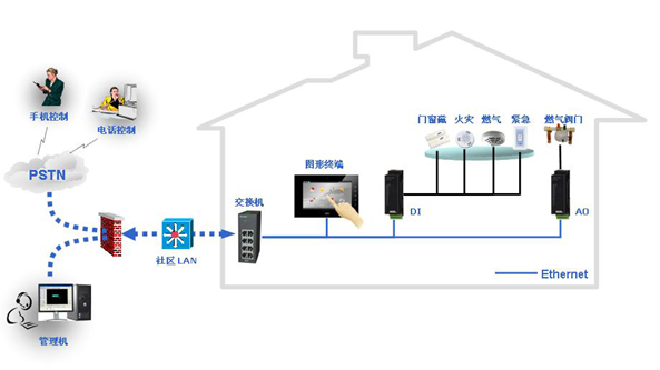
2. Security Alarm
The LT system has comprehensive security alarm functions that can timely alert illegal intrusions, gas leaks, fire alarms, etc. Once an alarm occurs, the graphical control terminal can automatically dial or send a text message to the resident’s designated phone or mobile phone to notify them, along with corresponding voice prompts to let the resident clearly know where the alarm occurred at home.
The monitoring map on the graphical control terminal can monitor the movements of intruders in real-time, and each graphical control terminal or monitor has an emergency alarm button, and there is also an emergency alarm touch button on the graphical control terminal interface. The security control system can also be programmed to configure actions that need to be automatically executed when the emergency alarm button is pressed or the alarm zone is triggered.
System Functions
nSend text messages to preset phone numbers;
nActivate alarms and emergency lighting;
nDisplay security status on the touch screen;
nGraphically display alarm locations;
nConfigurable actions after alarms;
nAnti-hijacking alarm;
nSupport three-layer security monitoring: alarm, disconnection, anti-tampering.
System Composition
nGraphical control terminal;
nCAN communication gateway;
nDI/DO module;
nEthernet switch;
nFront-end third-party security alarm detection devices.
System Architecture
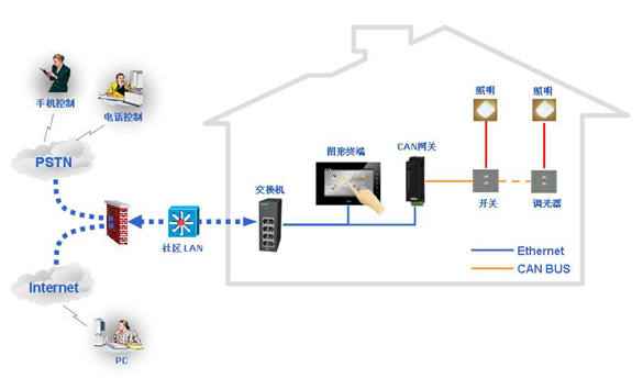
3. Lighting Control
Residents can use the panel or graphical control terminal to switch and adjust the brightness of indoor lights. They can control all lights in the system centrally or individually, or combine switching control with dimming control according to scenes to achieve certain lighting control effects.
For example, set a reception scene in the living room, a home scene; set a dining scene, a cleaning scene in the dining room, etc. It can also use outdoor light intensity to sense indoor light intensity, allowing residents to fully enjoy sunlight while achieving energy-saving goals.
By using the CAN bus, communication panels, dimmers, and switches, a simple lighting control system can be formed. Communication panels, dimmers, and switches can be controlled locally or configured through communication panels to achieve linkage and simple scene control. This system architecture ensures that lighting can still be controlled via local panels even when the system bus is powered down.
By connecting the above lighting control system to the CAN communication gateway, interconnection between Ethernet graphical control terminals and CAN bus devices can be achieved. The CAN communication gateway can broadcast data on the CAN bus to Ethernet devices registered in the gateway, thus achieving centralized and remote control of lighting through the graphical control terminal.
System Functions
nSingle light on/off and brightness adjustment;
nGroup lights on/off and brightness adjustment;
nBased on sunlight time, system status, and external sensing, control the brightness of single or group lights;
nPreset lighting operations and brightness adjustments. Lighting and curtain systems work together to achieve optimal indoor lighting.
System Composition
nGraphical control terminal;
nCAN communication gateway;
nEthernet switch;
nSwitches/dimmers.
System Architecture
4. Curtain Control
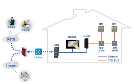
Residents can use the panel or graphical control terminal to adjust the position of the curtains, making their living space a safe and relaxing retreat. Curtain control can also be combined with lighting control to achieve various scene changes, maximizing energy savings.
By using the CAN bus, communication panels, and curtain controllers, a simple curtain control system can be formed. Communication panels and curtain controllers can be controlled locally or configured through communication panels to achieve linkage and simple scene control. This system architecture ensures that curtains can still be controlled via local panels even when the system bus is powered down.
By connecting the above curtain control system to the CAN communication gateway, interconnection between Ethernet graphical control terminals and CAN bus devices can be achieved. The CAN communication gateway can broadcast data on the CAN bus to Ethernet devices registered in the gateway, thus achieving centralized and remote control of curtains through the graphical control terminal.
System Functions
nSingle curtain on/off and position adjustment;
nGroup curtains on/off and position adjustment;
nBased on time, system status, and external conditions, control the position of single or group curtains;
nPreset curtain positions. Lighting and curtain systems work together to achieve optimal indoor lighting.
System Composition
nGraphical control terminal;
nCAN communication gateway;
nCurtain controller;
nEthernet switch.
System Architecture
5. Air Conditioning Control
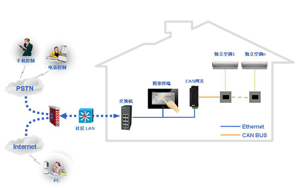
Independent air conditioning
The LT system’s air conditioning control function can control and adjust the temperature and air circulation of each room and provide real-time queries, keeping the cold and heat outside the window.
By using the CAN bus, communication panels, and infrared controllers, an independent air conditioning control system can be formed. In this system, residents can send commands to the infrared controller through the communication panel to control air conditioning devices.
By connecting the above air conditioning control system to the CAN communication gateway, interconnection between Ethernet graphical control terminals and CAN bus devices can be achieved. The CAN communication gateway can broadcast data on the CAN bus to Ethernet devices registered in the gateway, thus achieving centralized and remote control of air conditioning through the graphical control terminal.
System Functions
nSystem operation: open or close the air conditioning system;
nSystem fan: select wind speed (fast, medium, slow);
nSystem mode: selectable modes (cooling, heating, exhaust, automatic);
nTemperature: set, adjust, and display the temperature of each room.
System Composition
nGraphical control terminal;
nCAN communication gateway;
nInfrared controller;
nCommunication panel;
nEthernet switch.
System Architecture
Central Air Conditioning
The LT system’s air conditioning control function can control and adjust the temperature and air circulation of each room and provide real-time queries, keeping the cold and heat outside the window.
The LT central air conditioning control system consists of a graphical control terminal, communication protocol gateway, and communication interface provided by the air conditioning manufacturer. The communication interface can be an RS485 interface or Ethernet interface, and the air conditioning protocol can be LonWorks (fieldbus) or BACnet (Building Automation Control Network).
Taking Daikin VRV air conditioning as an example, it is necessary to connect the Daikin air conditioning host with the communication protocol gateway. By using configuration software, the device variables in the air conditioning host are bound to the address variables in the protocol gateway, and then the communication gateway is connected to the RS485 interface or Ethernet interface of the graphical control terminal in the LT system to integrate Daikin VRV air conditioning into the LT system.
System Functions
nSystem operation: open or close the air conditioning system;
nSystem fan: select wind speed (fast, medium, slow);
nSystem mode: selectable modes (cooling, heating, exhaust, automatic);
nTemperature: set, adjust, and display the temperature of each room.
System Composition
nGraphical control terminal;
nModbus/LonWorks protocol gateway;
nEthernet switch;
nProtocol gateway driver.
System Architecture
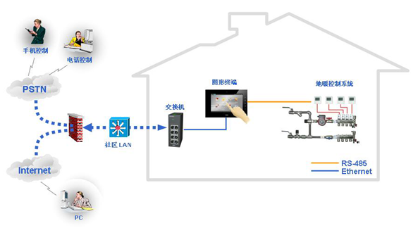
6. Floor Heating Control
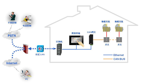
Protocol control
The LT system’s floor heating control function can easily achieve control and real-time queries for the switch, mode, and temperature of floor heating in each room.
The LT floor heating control system consists of a graphical control terminal, communication protocol gateway, and communication interface provided by the floor heating control panel manufacturer. The communication interface can be an RS485 interface.
Connecting the graphical control terminal of the LT system via the RS485 interface to the heating controller in each room can integrate the floor heating control system into the LT system based on the communication protocol provided by the floor heating control panel manufacturer.
System Functions
nSystem operation: open or close the floor heating system;
nTemperature: set, adjust, and display the temperature of each room.
System Composition
nGraphical control terminal;
nHeating controller;
nEthernet switch;
nProtocol gateway driver.
System Architecture
7. Fresh Air Control
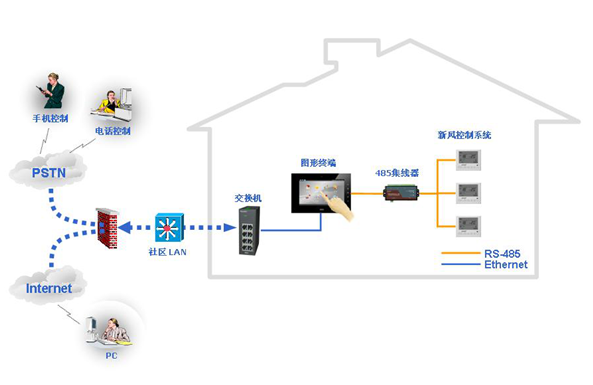
The LT fresh air control system can effectively control the fresh air switch and wind speed in each area and work in coordination with the air conditioning control system in the LT system, forming an intelligent control system that avoids the dust and noise caused by opening windows, making our rooms a house that can breathe.
The LT fresh air control system consists of a graphical control terminal, communication protocol gateway, and communication interface provided by the fresh air equipment manufacturer. The communication interface can be an RS485 interface.
Connecting the graphical control terminal of the LT system via the RS485 interface to the fresh air system control panel can integrate the fresh air control system into the LT system based on the communication protocol provided by the fresh air control panel manufacturer.
System Functions
nSystem operation: open or close the fresh air system;
nSystem wind speed: select wind speed (fast, medium, slow);
nInformation: display the working status of the fresh air system.
System Composition
nGraphical control terminal;
nFresh air control panel;
nProtocol gateway driver.
System Architecture
8. Media Control
Protocol control
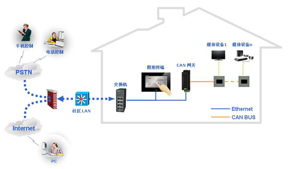
The LT media control system can easily control various rooms and any places requiring background music systems (including bathrooms, kitchens, and balconies). Residents can choose and control the audio and video signals sent to each room through a graphical interface, creating a wonderful audio-visual environment for the entire family.
The LT media control system consists of a graphical control terminal, communication protocol gateway, and communication interface provided by media device manufacturers.
The graphical control terminal connects to the background music host via the RS485 interface, using the communication protocol provided by the background music manufacturer to control media devices. The functions of the system depend on the compatibility of the selected audio and video system protocols and their host interfaces.
System Functions
nTrack selection;
nSwitching the previous and next tracks;
nVolume control;
nMute.
System Composition
nGraphical control terminal;
nBackground music host;
nEthernet switch;
nProtocol gateway driver.
System Architecture
9. Wireless Control
IPhone (ITouch or IPad)
The LT system has multifunctional adaptability, enabling wireless control functions for various household appliances such as: TVs, air conditioning, audio systems, DVDs, curtains, etc., combined with communication panels, switches, dimmers, and curtain controllers, LT devices can achieve wireless remote control of lighting and appliances in the home.
The system is equipped with an IPhone that can conveniently manage the smart home system devices at home. Since the signal uses Wi-Fi wireless communication transmission, it can control all family devices from any room in the house. For example, when you are resting in the bedroom, you can easily turn off unnecessary lights and appliances in the kitchen, corridor, balcony, and room using your IPhone without incurring any costs.
By connecting the IPhone to the LT system through a wireless router, downloading the customer application, and completing a simple configuration, interconnection between the IPhone and CAN bus devices can be achieved. The CAN communication gateway can broadcast data on the CAN bus to Ethernet devices registered in the gateway, thus enabling wireless access and control of system devices through the IPhone.
System Functions
nRemote switching: can emit wireless signals to control the “on” and “off” of various controllers, such as turning lights on and off, controlling curtains, etc.;
nDimming function: can emit wireless signals to control dimmers to adjust the brightness of the lights;
nScene mode: can output multiple scene modes to create different home scenarios, such as “home mode,” “away mode,” “dinner mode,” “cinema mode,” etc.;
nCan control air conditioning, floor heating, and other protocol communication devices through access to graphical terminals.
System Composition
nGraphical control terminal;
nCAN communication gateway;
nWireless router;
nIPhone (ITouch or IPad);
nEthernet switch.
10. Remote Control
Residents can remotely control various appliances at home through their phones. For instance, on the way home, they can pre-open the air conditioning or hot water heater.
Residents can also access the graphical control terminal at home via the Internet for web-based remote control. For example, users can input the IP address of the graphical control terminal at home on the Internet at the office, and after secure authentication, they can query and control the status of home appliances in the browser.
System Functions
nRemote control of air conditioning, floor heating, and fresh air switches;
nRemote arming and disarming;
nRemote query of the status of home devices.
System Composition
nGraphical control terminal;
nRemote control software;
nTelephone gateway (the graphical control terminal is built-in);
nNetwork switch.
Latest Premium Material Introduction
Recently released the articles from the second half of 2021 (up to December 31st). It includes plans, images, and basically covers articles on various systems in the intelligent weak current industry, and also provides 16 sets of premium materials, each with a title for easy content search. For example, search for materials related to video surveillance. This material is very suitable for newcomers to learn, especially for those who have no time and do not know how to search for materials, with a total ofover 3000 files. It is recommended to get a set; it will definitely be helpful!
All PPT plans in the article are provided for free, totaling 167 PPTs, 6 complete drawings, 230 industry standards and construction drawing collections,133 Word plans, 15 construction organization designs, 20 bill of quantities, drawings, and materials 61,VISIO blocks and topology diagrams, project management and construction plans, bills of quantities with quotes, bidding plans, and construction organization designs,etc.
You can click the link below to view related content
Summary of materials from the second half of 2021, upgrade updates, and 2600+ weak current materials are provided for free
Brother Xue’s Summary:
If you need articles from the first half of 2021, you can check at the link below:
Summary of materials from the first half of 2021, with a lot of updates, providing over 2300 weak current materials for free
If you need articles from the second half of 2020, you can check at the link below:
Summary of articles from the second half of 2020, materials upgraded again, providing over 2000 weak current materials for free
Free weak current materials are available, click the link below if needed
Latest free weak current materials, with download methods attached
All weak current system materials (free)
Some video tutorials on intelligent weak current systems (free)
Providing 90 industry standards and specifications for intelligent weak current
Good articles should be shared; sharing is a virtue, helping others is helping yourself.
If you encounter problems while learning weak current industry knowledge, feel free to consult me! I am willing to provide some help to those who are just starting out. Welcome everyone to add my QQnumber 81113907 or WeChat ruodianxuege
Weak Current Growth Club (VIP Group) Group 6 is currently recruiting members, with 2500 elites already joining us, welcome weak current workers to join! Joining the group now can get premium materials and connect with 2500 networking resources.
Our purpose is to share knowledge, share resources, cooperate for mutual benefit, and grow together!
For specific details, click the link below:
Weak Current Growth Club (VIP) Group 6 established, a high-end networking circle, looking forward to your joining!

Scan the QR code | Follow us
WeChat ID | ruodianxuege, kkiiss
Brother Xue, a first-level constructor, founder of the Weak Current Growth Club, proficient in the entire process of intelligence, looking forward to cooperating with you!
Brother Xue updates knowledge about intelligent weak current every day, welcome everyone to communicate.
Looking forward to your
sharing
likes
views
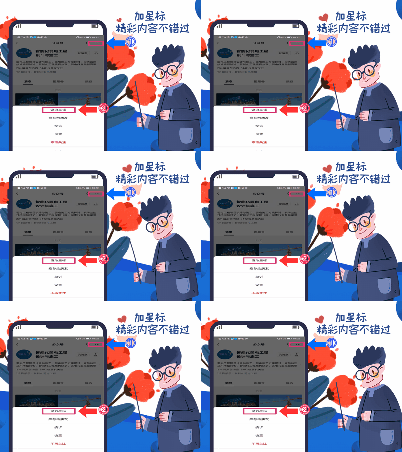
Postscript: Due to WeChat modifying the push rules, those who do not frequently leave comments or click“views” will slowly stop receiving pushes! If you still want to see our pushes every day, please add “Brother Xue’s public account” as a star mark or click the bottom of the page after reading each time“like” “views”, thank you!