Abstract:The robotic arm uses ARM chips as the control core, mainly due to its strong computing power, rich peripheral interfaces, and the ability to expand into various interfaces such as serial, parallel, high-speed, and low-speed. It can also easily expand into network interfaces, facilitating collaborative work of robotic arms. In particular, the LCD interface and memory expansion interface of ARM chips can significantly improve the intelligence level of the robotic arm. After expanding the LCD, it can provide a user-friendly human-machine interface, making programming, maintenance, and fault indication easier; large-capacity memory can facilitate complex calculations and large data storage. These advantages of ARM provide the most effective guarantee for the high intelligence of robotic arms.
1 Introduction The application of robots is an important indicator of a country’s industrial automation level. In industrial automation, robotic arms play a significant role. The use of robotic arms in production can reduce labor intensity, ensure product quality, and achieve safe production; especially in high-temperature, high-pressure, explosive, radioactive, or toxic environments, robotic arms can replace humans to perform normal work. Particularly in recent years, as labor costs have risen, companies urgently need to adopt automated equipment to reduce labor costs, and industrial robotic arms have broad application prospects in this regard. Most commonly used robotic arms have less than 6 degrees of freedom. General-purpose robotic arms usually have 3 to 6 degrees of freedom, while specialized robotic arms typically have 2 to 4 degrees of freedom. Currently, most industrial robotic arms are controlled by microcontrollers, PLCs, or DSPs. Microcontrollers can only control simple robotic arms with less than 3 degrees of freedom; PLC control is costly, has poor computing power, and is weak in controlling the motion trajectory of robotic arms; DSPs have strong computing capabilities but lack the rich peripheral interfaces of ARM and are also more expensive. A robotic arm with 6 degrees of freedom and more complex control requires multiple DSP chips to collaborate for effective control.
1.1 Design of 4 Degrees of Freedom The mechanical gripper uses the model 42HD2401-100L, a two-phase four-wire stepper motor. The stroke of the screw motor is 100 mm, with a step angle of 1.8° and a current of 1.5 A N1504. By utilizing different strokes, grippers or fixtures with varying torque can be designed. This part is locked onto the model 42BYG planetary reduction stepper motor via a processed connecting shaft with screws, equipped with a 48 mm stepper motor and a reduction ratio of 5.18:1, allowing the mechanical gripper to rotate within a 360° range, thus controlling the first degree of freedom of the robotic arm.
The second degree of freedom device is responsible for fixing the motor of the first degree of freedom and controlling its motion within a certain angular range. According to the structure of the selected worm gear reducer, the angular range is 0~130°. The motor is a 57 stepper motor (57BYG250H), with a torque of 2.8 NM, a step angle of 1.8°, a body length of 112 mm, and a worm gear reducer NMRV030 with a reduction ratio of 1:20.
The motor model used for the third degree of freedom is 86HS45-80, a two-phase stepper with a step angle of 1.8°, a body length of 78 mm, a current of 4 A, and a holding torque of 4.24 NM. It is equipped with a worm gear reducer RV040 with a reduction ratio of 1:20.
The fourth degree of freedom is mainly responsible for 360° rotation in the plane, using the same motor as the second degree of freedom, with a reduction ratio of 1:30 for the reducer. This motor is mounted on the base.
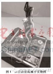
1.2 Motor Driver Selection and Mechanical Assembly The robotic arm has 4 degrees of freedom and 1 mechanical gripper, using a total of 5 different specifications of stepper motors. The 86 model motor uses F-MD860, while the others use DM542, equipped with two 24V power supplies rated at 250W for power supply. The physical diagram after all mechanical parts are assembled is shown in Figure 1. The base is constructed from galvanized square tubes welded into a double-layer iron structure measuring 100 mm × 100 mm, with the bottom motor fixed by angle iron. The entire assembly is spray-painted for rust prevention, and the wires are sealed and fixed with retractable plastic tubes to prevent entanglement or damage.
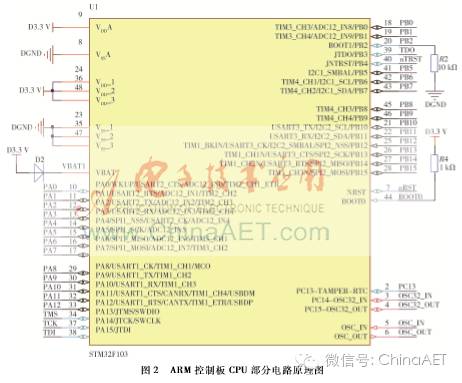
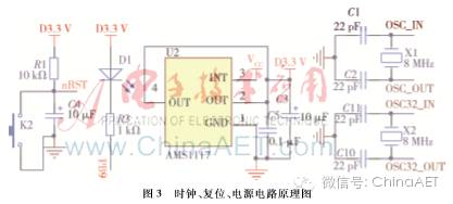
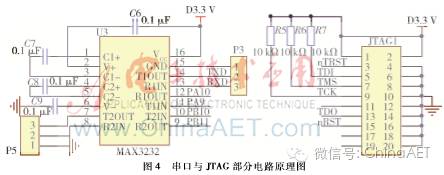
2 Hardware Design of Robotic Arm Control System The control core of the robotic arm is designed using a powerful ARM chip, model STM32F103C8T6, with 48 pins. The control board receives serial communication data from the host computer and converts it into pulse signals to control the stepper motors according to the data protocol. The control board uses double-row pins to expose all GPIOs for flexible expansion. The schematic diagram is drawn using Altium Designer 10 software; the CPU circuit schematic of the ARM control board is shown in Figure 2, while the clock, reset, and power circuit schematic is shown in Figure 3, and the serial and JTAG circuit schematic is shown in Figure 4.
The specific parameter indicators of the robotic arm are as follows: the structure material is all metal; the drive mode is stepper servo hybrid drive; the operation mode adopts programmable single-machine work/online work; repeat positioning accuracy is ±5 mm; maximum expansion radius is 600 mm; height is 1,000 mm; body weight ≤ 50 kg; power supply is single-phase 220V; maximum power < 200W; motion range for the first degree of freedom is -180° to 180°, with a speed range of 0.5°/s to 50°/s; for the second degree of freedom, the range is -65° to 65°, with a speed range of 0.5°/s to 30°/s; for the third degree of freedom, the range is -65° to 65°, with a speed range of 0.5°/s to 30°/s; for the fourth degree of freedom, the range is -180° to 180°, with a speed range of 0.5°/s to 40°/s.
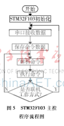
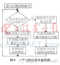
3 Software Design of Robotic Arm Control System 3.1 Design of ARM Control Board Software The development environment used is Keil uVision3 + MDK3.50. The program on the ARM control board mainly includes control of serial communication and generation of pulse waveforms. The flowchart of the main control program is shown in Figure 5. The STM32F103 first needs to be initialized, with the following initialization contents: RCC_Configuration(void), NVIC_Configuration(void), GPIO_Configuration(void), USART_Init(USART1, &USART_InitStructure), and TIM3_PWM_Init(u16 arr, u16 psc). Serial communication requires setting GPIO pins, with the serial port set to a baud rate of 9600 b/s, 8-bit data, 2 stop bits, no parity bit, and no hardware flow control. Finally, the serial receive interrupt initialization setting must be performed as follows: NVIC_InitStructure.NVIC_IRQChannel = USART1_IRQChannel; NVIC_InitStructure.NVIC_IRQChannelPreemptionPriority = 0; NVIC_InitStructure.NVIC_IRQChannelSubPriority = 0; NVIC_InitStructure.NVIC_IRQChannelCmd = ENABLE; NVIC_Init(&NVIC_InitStructure). To ensure that the ARM control board can independently control the robotic arm’s motion after receiving command parameters, data must be stored in the ARM chip’s Flash memory, then read, parsed, and executed. The program flowchart is shown in Figure 6.
Moreover, for pulse waveform generation, the hardware timer unit built into the ARM chip is used to generate frequency-adjustable square waves. The timer interrupt initialization program is as follows: void Timerx_Init(u16 arr, u16 psc) { RCC->APB1ENR |= 1 << 1; // Enable TIM3 clock TIM3->ARR = arr; // Set counter auto-reload value to 1 ms
TIM3->PSC = psc; // Prescaler 7200, obtaining a 10 kHz counting clock TIM3->DIER |= 1 << 0; // Allow update interrupt TIM3->DIER |= 1 << 6; // Allow trigger interrupt TIM3->CR1 |= 0x01; // Enable timer 3 MY_NVIC_Init(1, 3, TIM3_IRQChannel, 2); // Preemption 1, sub-priority 3, group 2 } The long-period square waves are generated using the above timer interrupt overflow for timing. This method allows for long delays, suitable for controlling various action speeds. For faster movements, the hardware PWM unit in STM32F103 can be directly used to generate square waves with shorter periods. The main control source program is as follows: void TIM3_PWM_Init(u16 arr, u16 psc) { // This part needs manual modification of IO port settings RCC->APB1ENR |= 1 << 1; // Enable TIM3 clock RCC->APB2ENR |= 1 << 3; // Enable PORTB clock GPIOB->CRL &= 0XFF0FFFFF; // PB5 output GPIOB->CRL |= 0X00B00000; // Multiplex function output RCC->APB2ENR |= 1 << 0; // Enable auxiliary clock AFIO->MAPR &= 0XFFFFF3FF; // Clear MAPR [11:10] AFIO->MAPR |= 1 << 11; // Partial remap, TIM3_CH2 -> PB5 TIM3->ARR = arr; // Set counter auto-reload value TIM3->PSC = psc; // Prescaler no division TIM3->CCMR1 |= 7 << 12; // CH2 PWM2 mode TIM3->CCMR1 |= 1 << 11; // CH2 preload enable TIM3->CCER |= 1 << 4; // OC2 output enable TIM3->CR1 = 0x0080; // ARPE enable TIM3->CR1 |= 0x01; // Enable timer 3 } 3.2 Design of Upper Computer Software for Robotic Arm The upper computer program mainly completes the setting of motion position parameters for the robotic arm and transmits data to the ARM development board via serial port. During debugging, motion control is divided into single-axis control and three-axis control. The single-axis control interface is shown in Figure 7, and the three-axis motion control interface is shown in Figure 8, where the starting and ending coordinates in the x, y, z directions are entered, and data can be sent to the lower computer after starting.
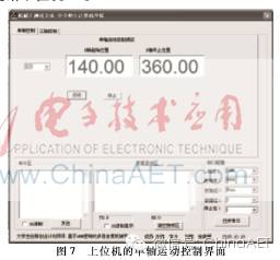
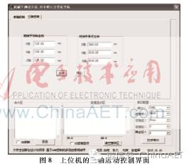
On the interface, there is also a serial communication data monitoring window that mainly displays whether the sent commands and received data are normal, which facilitates development. In the serial data communication programming, the CSerialPort class is used for programming, initializing the serial port, baud rate, data bits, stop bits, parity bits, etc. The main function used is InitPort(), as follows: if(m_Port.InitPort(this, m_nCom, m_nBaud, m_cParity, m_nDatabits, m_nStopbits, m_dwCommEvents, 512)) { m_Port.StartMonitoring(); m_CtrlOpenPort.SetWindowText(“Open Serial Port”); m_Port.ClosePort(); // Close serial port } else AfxMessageBox(“No such serial port found”); The main statement for sending data is as follows: sendcommand = m_strSendData; m_Port.WriteToPort((LPCTSTR)sendcommand); // Send data Receiving data is handled in the CSerialPort class, which can receive interrupts, but data recognition must be performed in the main program. This paper specifically parses the received data in the LONG CICtestDlg::OnCommunication(WPARAM ch, LPARAM port) function.
4 Conclusion This project mainly utilizes ARM series CPUs as the control core to drive a certain number of servos to assemble a multi-degree-of-freedom robotic arm device. Compared with traditional robotic arm control systems, this system has advantages such as small size, low power consumption, high performance, and low cost, with a good development prospect. The repeat positioning accuracy has not reached the pre-estimated value, which is related to the manufacturing precision of the purchased motors and reducers. Additionally, stepper motors may lose steps during operation, so there are many aspects that need improvement, such as installing encoders for motion angle detection in the motion control of each motor, which can improve accuracy and completely eliminate the issue of losing steps.
References [1] Li Xinrong, Qu Fengjuan. Design and Application of ARM9 Embedded System [M]. Beijing: Tsinghua University Press, 2011.
[2] Li Haibiao, Gan Zhenzhao, Yang Shuo. Design of Robotic Arm Control System Based on ARM9 [J]. Measurement and Control Technology, 2015, 34(8): 82-85. [3] Ye Xiaodong. Design of Simple Robotic Arm Based on Microcontroller [J]. Microcomputer Information, 2009, 25(14): 230-231. [4] Sun Yanwei. Design and Implementation of Teaching System for Five-Axis Injection Molding Machine Robotic Arm [D]. Xi’an: Xi’an University of Electronic Science and Technology, 2013. [5] Yang Zhensheng. Hardware Design of Industrial Robotic Arm Control System [D]. Xi’an: Xi’an University of Electronic Science and Technology, 2014. [6] Xiang Dan, Wang Wentao, Yuan Jianzong, et al. Design of Remote Control System for Three-Dimensional Robotic Arm Based on ARM Embedded System [J]. Electronics and Packaging, 2009, 9(6): 21-24. [7] Yang Li, Li Zhengming, Liu Baosen. Design of Embedded CNC Milling Machine Control System Based on ARM9 [J]. Machine Tool Electrical, 2008, 35(2): 8-11. [8] Li Kun, Yang Jiajun. Kinematic Research on 5-Degree-of-Freedom Welding Robotic Arm [J]. Mechanical Engineer, 2007(4): 20-21. [9] He Yang. Design and Implementation of Upper Computer Controller for Three-Axis Servo Injection Molding Machine Robotic Arm [D]. Hangzhou: Zhejiang University, 2012. [10] Li Tao. Software Design and Implementation of Servo Robotic Arm Controller [D]. Xi’an: Xi’an University of Electronic Science and Technology, 2013.