
Introduction:The stratospheric airship sensor data measurement device is used to collect the pressure difference inside and outside the airship’s envelope, the atmospheric pressure of the environment where the airship is located, and the voltage of the power supply battery. The processed data is packaged and sent to the flight control computer, providing key parameters for the safe flight of the airship. It can also record and store data online for post-flight data analysis and playback. Based on the TMS320F2812 and discrete components, an embedded system has been designed and a prototype has been developed. The design includes redundancy to improve the reliability of data acquisition and communication, enhancing the integration and accuracy of sensor measurements, providing important evidence for the flight control of stratospheric airships.
DOI: 10.19358/j.issn.2096-5133.2019.02.017
Design of DSP-Based Embedded System for Sensor Data Acquisition
XU Wenkun, WANG Baocheng, ZHOU Jianghua, MIAO Jinggang
(Institute of Optoelectronics, Chinese Academy of Sciences, Beijing 100094)
Keywords: Stratospheric Airship; Data Acquisition and Storage; Pressure Difference; Atmospheric Pressure; Battery Voltage; DSP Processor; Embedded System
Classification Number: TP302.1
Literature Identification Code: A
Citation Format: XU Wenkun, WANG Baocheng, ZHOU Jianghua, et al. Design of DSP-Based Embedded System for Sensor Data Acquisition [J]. Information Technology and Network Security, 2019, 38(2): 66-70.
0 Introduction
The stratospheric airship flies in near-space (the range between the flight altitude of airplanes and spacecraft, generally defined as 18-100 km, an urgently needed area with important strategic significance), is an aircraft that utilizes the buoyancy of lighter-than-air gases to provide lift, and is one of the main aircraft in the near-space region[1-2].
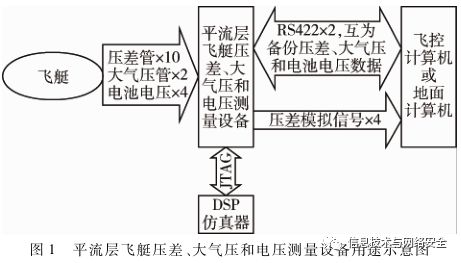
Stratospheric airships usually use soft airship designs, maintaining their shape rigidity through the pressure difference inside and outside the envelope; atmospheric pressure data is used to calculate the altitude of the airship; battery voltage is used to monitor the voltage of the power supply batteries for various devices. These data need to be provided to the flight control computer as key parameters for pressure control and safe flight. Therefore, accurately obtaining these parameters is particularly important, necessitating the design of dedicated equipment (its purpose is shown in Figure 1) to acquire these parameters[3].
This paper designs a pressure difference, atmospheric pressure, and voltage measurement device for stratospheric airships, using discrete sensors and electronic components, designing data acquisition and processing circuits, integrated on a single printed circuit board, and writing embedded programs based on DSP to solidify into the hardware, developing a prototype and conducting experiments. In the design, redundancy was incorporated for critical pressure difference data and communication interfaces to improve reliability. This device completes sensor data acquisition and communication while also being able to record and store data online[4-5].
1 Design Scheme
This design scheme includes hardware design and software design, which are explained separately below.
1.1 Hardware Design[6-9]
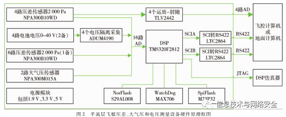
The hardware principle block diagram is shown in Figure 2. In this design, the pressure difference sensor, atmospheric pressure sensor, and battery voltage measurement circuit are all integrated on a PCB, using DSP to collect and process all signals, and perform online recording and storage, thus communicating with the flight control computer.
To improve the reliability of the device’s functionality, some redundancy designs were made, mainly including three aspects.
(1) Redundant designs for pressure difference acquisition, atmospheric pressure acquisition, and battery voltage acquisition.
(2) Redundant design for serial communication with the flight control computer, where the DSP processes and packages all collected data, converting it through its two SCI ports into RS422 for independent communication with the flight control computer, enhancing the reliability of data communication.
(3) Four key pressure difference information channels directly send the analog signal (without going through DSP) to the AD acquisition port of the flight control computer through the TLV2442 operational amplifier, allowing the flight control computer to still acquire four key pressure difference information even if the DSP fails.
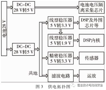
The power supply module mainly provides five power supplies, including two 5 V supplies, two 3.3 V supplies, and one 1.9 V supply. Among them, one 5 V supply is isolated from other supplies to power the input stage of the isolated battery voltage acquisition chip; one 5 V is for operational amplifier power; one 3.3 V powers the pressure difference sensor and atmospheric pressure sensor; one 3.3 V powers the DSP and other peripheral chips; one 1.9 V powers the DSP core. Its power topology diagram is shown in Figure 3.
The pressure difference sensor model is NPA300B10WD[10], an automotive-grade chip with a range of ±2,500 Pa, a working current of 1 mA, and an output analog signal of 0-3 V, with temperature compensation from 0-70 ℃. The atmospheric pressure sensor model is NPA300M015A, also an automotive-grade chip, with a range of 0-103 kPa, a working current of 1 mA, and an output analog signal of 0-3 V, also with temperature compensation from 0-70 ℃. The battery voltage acquisition uses the isolated acquisition chip ADUM4190SRIZ, a military-grade device, with isolated input and output, an input voltage range of 0-3 V, and with a voltage divider circuit at its input, the acquisition voltage range can reach 0-40 V.
This scheme uses TI’s TMS320F2812 as the main control CPU, with a working frequency of up to 150 MHz, mainly utilizing resources including 16 ADC interfaces, 2 SCI interfaces, 1 SPI interface, parallel data interface, and JTAG interface.
The NorFlash model is S29AL008, with a parallel interface and a capacity of 8 Mbit, used to store sensor calibration data. The SPI interface Flash model is M25P32, with a capacity of 32 Mbit, used for online storage of sensor data. The MAX706 is an external hardware watchdog chip that can restart the DSP through an external reset signal if the DSP crashes, improving the reliability of system operation. The LTC2864 chip is used to convert the SCI interface to RS422 for communication with the flight control computer.
1.2 Software Design
The software tasks of this device mainly include data acquisition and processing, communication with the flight control computer, as well as sensor calibration, data storage, and other functions. During the joint testing of the airship system, field testing, and flight testing, it real-time collects data from 10 pressure difference sensors, 2 atmospheric pressure sensors, and 4 battery voltage sensors, performs filtering and processing, and sends the data simultaneously to the flight control computer through 2 RS422 communication interfaces, with the two RS422 communication interfaces serving as backups; these two interfaces can also connect to ground computers for ground debugging, including data communication, data monitoring, and sensor calibration, etc. At the same time, it has online data storage functionality, allowing the flight control computer to call or download data from the ground computer at any time. Its software functionality differs significantly from that of general aviation aircraft in that it has ground mode and take-off mode, requiring switching before flight. It has two working modes, explained as follows.
(1) Communication Mode with Flight Control Computer
This mode is the final working mode during airship flight, mainly completing fixed-cycle communication with the flight control computer, time synchronization, data erasure, and online storage, with relatively simple functionality.
In this mode, after connecting the system to the flight control computer, it defaults to sending sensor data to the flight control computer via two RS422 serial ports at a frequency of 10 Hz upon startup, but does not store it in the built-in SpiFlash. Before the airship takes off, it first receives the SpiFlash erase command sent by the flight control computer through the two RS422 serial ports, erases the SpiFlash, during which time it stops sending data externally; after erasure, it sends an erase success command to the flight control computer through the two RS422 serial ports, then receives the time synchronization command sent by the flight control computer through the two RS422 serial ports, starts the internal time synchronization counter, and begins sending sensor data to the flight control computer at a frequency of 10 Hz while storing data in SpiFlash at a frequency of 0.5 Hz.
(2) Ground Debugging Mode
This mode mainly operates during device testing and debugging processes, verifying the normal operating state of the device, debugging various functions, and ground calibration of sensors, etc.
In this mode, in addition to completing the same functions as the communication mode with the flight control computer, it also needs to have the following functions.
NorFlash Erasure Function: Receives the NorFlash erase command sent by the ground computer through the two RS422 serial ports, initiates the NorFlash erase function, erases the NorFlash, and returns an erase success or failure identifier, sent to the ground computer through the two SCI serial ports.
NorFlash Write Calibration Data Function: Receives calibration data (including the slope and zero offset of each sensor) sent by the ground computer through the two RS422 serial ports, initiates the NorFlash write function, writes the calibration data into the NorFlash, so that the system can read the calibration data for data conversion each time it starts.
NorFlash Data Reading Function: Can read the calibration data stored in NorFlash at any time; the system reads calibration data from NorFlash and stores it in global variables each time it starts; when it receives the NorFlash read command sent by the ground computer through the two RS422 serial ports, it initiates the NorFlash data reading function, reads the data stored in NorFlash, and sends it to the ground computer through the two RS422 serial ports.
SpiFlash Data Reading Function: Receives the command sent by the ground computer through the two RS422 serial ports, initiates the data reading function, reads the data stored in SpiFlash, and sends it to the ground computer through the two RS422 serial ports.
Sensor Calibration Function: Collects voltage data through AD, performs median filtering on the data, and packages it. According to the command received from the ground computer through the two RS422 serial ports to send sensor voltage data, it sends the filtered voltage data through the two RS422 serial ports to the ground computer. Using this data, sensors can be calibrated.
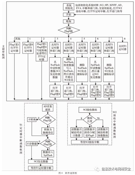
The main function of the software is to collect and process AD data and send it out via the two SCI serial ports at a frequency of 10 Hz, so the software prioritizes ensuring the normal implementation of this function; it also incorporates the realization of other auxiliary functions. It uses Timer T1 to generate a periodic interrupt every 100 ms, in the interrupt function, it continuously queries and samples the 16 channels of AD 10 times, performs median filtering, converts it to final unit data, and packages it, then sends it out through the two SCI serial ports. Meanwhile, it enables SCI receive interrupts to receive external commands, judge them, and execute different program functions. The entire software flowchart is shown in Figure 4.
2 Experimental Results Analysis
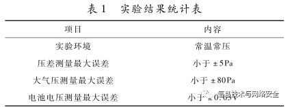
After the prototype was completed, component-level experiments were conducted under normal temperature and pressure conditions, with a supply voltage of 28 V, a current of 0.07 A, and a power consumption of less than 2 W. The experimental results of pressure difference acquisition, atmospheric pressure acquisition, and battery voltage measurement are shown in Table 1, explained separately below.
2.1 Pressure Difference Measurement Experimental Results Analysis
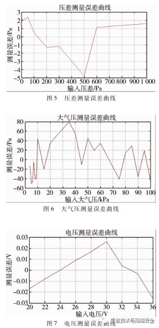
Using the Setra-869 standard pressure difference source[11] as the pressure difference input, the prototype’s 10 pressure difference collections work simultaneously, collecting 10 pressure difference results with an average error of less than ±2 Pa. The maximum error of one set of results is shown in Figure 5. As can be seen from the figure, the maximum error is less than ±5 Pa. Since the pressure difference measurement range available for stratospheric airships is 0-1,000 Pa, this experiment only tested this range.
2.2 Atmospheric Pressure Measurement Experimental Results Analysis
Using the Huaxin HS108 standard atmospheric pressure source[12] as the atmospheric pressure input, the prototype’s 2 atmospheric pressure collections work simultaneously, collecting 2 atmospheric pressure results with an average error of less than ±40 Pa. The maximum error of one set of results is shown in Figure 6. As can be seen from the figure, the maximum error is less than ±80 Pa. Since the atmospheric pressure measurement range available for stratospheric airships is 4-100 kPa, this experiment only tested this range.
2.3 Voltage Measurement Experimental Results Analysis
Using the Huaxin HS108 standard atmospheric pressure source as the atmospheric pressure input, the prototype’s 2 atmospheric pressure collections work simultaneously, collecting 2 atmospheric pressure results with an average error of less than ±40 Pa. The maximum error of one set of results is shown in Figure 6. As can be seen from the figure, the maximum error is less than ±80 Pa. Since the atmospheric pressure measurement range available for stratospheric airships is 4-100 kPa, this experiment only tested this range.
3 Conclusion
This paper proposes a design scheme for integrated measurement devices for pressure difference, atmospheric pressure, and battery voltage of stratospheric airships, completing the design of both hardware and software and the development of prototypes, along with experiments. Experimental data indicates that the measurement accuracy of pressure difference, atmospheric pressure, and battery voltage of this design reaches ±5 Pa, ±80 Pa, and ±0.03 V, respectively, meeting the requirements of the stratospheric airship flight control system. Meanwhile, this design incorporates redundancy to improve the reliability of system functions; it has online data storage functionality, providing a basis for post-flight data analysis; it has high integration and low power consumption.
References
[1] YANG Yanchu, WANG Sheng, GU Yidong, et al. Multidisciplinary Optimization Design of Near-Space Airships Based on Genetic Algorithms [J]. Computer Simulation, 2012, 29(4):49-54.
[2] Reference URL: http://www.gov.cn/jrzg/2006-02/09/content_ 183787_4.htm
[3] (UK) G.A. Cooley, J.D. Gillette. Airship Technology [M]. WANG Sheng, et al., Trans. Beijing: Science Press, 2008.
[4] JIANG Leping. Research on DSP-Based Flight Control System for Solar Airships [D]. Nanchang: Nanchang Hangkong University, 2012.
[5] SHI Xingzu. Data Acquisition, Control, and Implementation in Small Low-Altitude Airships [D]. Shanghai: Shanghai Jiao Tong University, 2009.
[6] ZHU Kai, WU Ruiqing, ZHANG Lei, et al. Research and Implementation of DSP-Based Magnetic Vibration Heat System [J]. Electronic Technology Application, 2015, 41(8):13-16.
[7] ZHANG Dong. Analysis of ADC Conversion Accuracy of TMS320F2812 Chip [J]. Electronic Technology Application, 2010, 36(9):68-70.
[8] GU Weigang. Hands-on Guide to Learning DSP [M]. Beijing: Beihang University Press, 2015.
[9] YAN Shi, Tsinghua University Electronics Teaching and Research Group. Fundamentals of Digital Electronic Technology [M]. Beijing: Higher Education Press, 2016.
[10] Amphenol Advanced Sensors NPA Low Pressure Sensors [EB/OL]. [2018-11-26]. https://www.mouser.com/new/amphenol- advanced-sensors/amphenol-npa-low-pressure-sensors/.
[11] Setra Product Lines [EB/OL]. [2018-11-26]. https://www.setra.com/products#calibration.
[12] Huaxin Instruments. Pressure Source Series Products [EB/OL]. [2018-11-26]. www.9511.com.cn/index.php?optionid=144 &auto_id=30.
(Received Date: 2018-11-26)
Author Profiles:
XU Wenkun (1982-), corresponding author, male, master’s degree, senior engineer, main research direction: avionic technology.
WANG Baocheng (1974-), male, PhD, associate researcher, main research direction: avionic technology.
ZHOU Jianghua (1973-), male, PhD, researcher, main research direction: flight control technology.
(Text Editor: ZHOU Bin)


(For the convenience of readers, a subscription service has been launched in cooperation with Beijing Zhongke Journal Publishing Co., Ltd., and a Taobao store and WeChat store are now open, looking forward to your visit!)
Extended Reading:
Joint Innovation to Promote the Construction of Industrial Control Security Assurance System
Xinhua News: The National Engineering Joint Laboratory for Information Security Technology of Industrial Control Systems is inaugurated in Beijing
“Industrial Internet Development Action Plan (2018-2020)” (Full Text Attached)
Implementation Rules for Security Certification of Key Network Devices and Special Products for Network Security (Full Text)
“Information Technology and Network Security” Journal Online Submission System:http://www.pcachina.com
ISSN 2096-5133
CN 10-1543/TP
Postal Distribution Code 82-417