Skip to content
As we all know, the engine speedometer in a car dashboard can monitor and display the engine speed in real-time, such as 1200 revolutions per minute. If we perform open-source hardware programming with a Raspberry Pi, utilizing a Hall sensor to detect magnetic fields and count the number of rotations, we can ultimately develop a highly efficient and practical Raspberry Pi fan speed meter.
1. Experimental Equipment and Connection Method
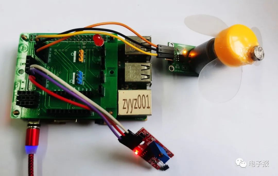
The experimental equipment includes one Raspberry Pi 3B+ and one Good Micro expansion board, one KY-024 Hall sensor, one fan module, one red LED light, one small round magnet, and several Dupont wires.
First, correctly install the Good Micro expansion board onto the Raspberry Pi, then insert the red LED light into pin 5 of the expansion board according to the principle of “long leg positive, short leg negative”; the Hall sensor has four pins, where the VCC and GND pins are connected to the VCC power positive and GND ground of pin 25 on the expansion board using Dupont wires. The other two pins are marked as DO (digital signal) and AO (analog signal), and only the D0 digital signal pin needs to be connected to the D pin of pin 25 on the expansion board using Dupont wires; next, use hot melt glue to attach the small round magnet to the edge of the fan, then connect the VCC, GND, and IA pins of the fan module to the VCC, GND, and D pins of pin 24 on the expansion board respectively; finally, power on the Raspberry Pi and start the operating system (as shown in Figure 1).
2. Implementing the Fan Speed Meter Design with “Block” Graphical Programming
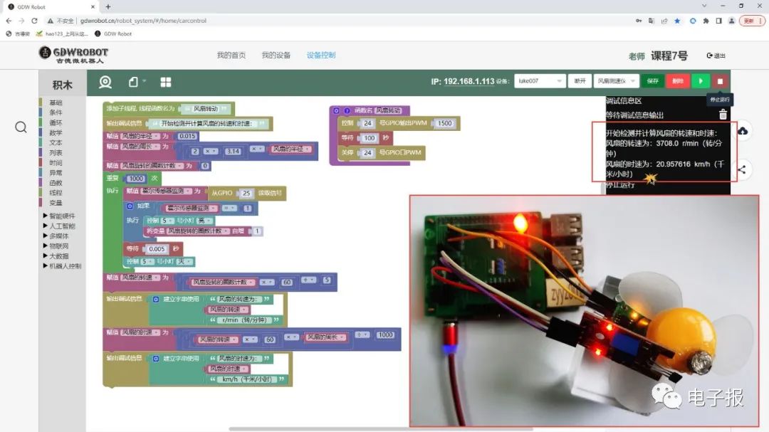
Access the Good Micro Robot website in your browser, log in to your account, and enter the “Block” graphical programming interface. First, create a new function named “Fan Rotation”, where the running modules include “Control GPIO 24 to output PWM1500”, “Wait 100 seconds”, and “Stop GPIO 24 PWM”, which functions to control the fan module connected to pin 24 to rotate at a PWM value of 1500, which can be set arbitrarily between 0 and 3000; then, add a sub-thread from the left “Thread” section, setting the parameter “Thread Function Name” to the newly created “Fan Rotation” function; output debugging information: “Starting to detect and calculate the fan’s speed and speed:”; then create a variable “Fan Radius” and assign it a value of 0.015 (in meters) — the measured radius of the fan is about 1.5 centimeters; create a variable “Fan Circumference”, assigning it the value of “2 multiplied by 3.14 multiplied by Fan Radius”, which is the circumference calculation formula; create a variable “Fan Rotation Count”, assigning it the value of 0, which serves to count how many rotations the fan has completed within 5 seconds.
Establish a loop structure that executes “1000 times”, assigning the newly created variable “Hall Sensor Monitoring” the value of “Read signal from GPIO 25” (because the Hall sensor’s D0 signal pin is connected to the D pin of pin 25 on the expansion board); establish a selection structure “If… Execute…”, where the condition checks if the value of the variable “Hall Sensor Monitoring” is 1 (high level). If the condition is met, it indicates that the Hall sensor has detected the small magnet approaching, performing the actions of turning on the light (the red LED light on pin 5) and incrementing the variable “Fan Rotation Count” by 1; the former serves as a visual prompt, while the latter serves to calculate the number of rotations — the fan has completed another rotation; then, add a “Wait 0.005 seconds” delay module and turn off the red LED light; thus, this loop executing 1000 times will take a total of “1000 multiplied by 0.005”, which is 5 seconds.
Next, create a variable “Fan Speed”, assigning it the value of “Fan Rotation Count multiplied by 60 divided by 5”, which calculates the number of rotations per minute based on the effective count of rotations in 5 seconds; then, output debugging information: “The fan speed is:”, the variable “Fan Speed” value, and “r/min (revolutions/minute)”; create a variable “Fan Speed”, assigning it the value of “Fan Speed multiplied by 60 multiplied by Fan Circumference divided by 1000”; similarly output debugging information: “The fan speed is:”, the variable “Fan Speed” and “km/h (kilometers/hour)”.
Save the program as “Fan Speed Meter”, click “Connect Device” and then click the “Run” button; note to place the Hall sensor’s sensing probe near the small round magnet of the fan; as the fan rotates, the red LED light will flash continuously, and the debugging information on the screen will display the message “Starting to detect and calculate the fan’s speed and speed:”; after about 5 seconds, the calculation results will be displayed: “The fan speed is: 3708.0 r/min (revolutions/minute)”, “The fan speed is: 20.957616 km/h (kilometers/hour)” (as shown in Figure 2).
Everyone might as well give it a try. (Related programs can be obtained by contacting this newspaper)
Zhaoyuan No. 1 High School, Mu Xiaodong