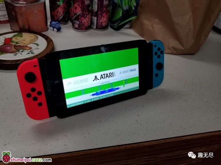
This is a gaming console made with a Raspberry Pi that resembles a Switch. The author cfoote7 wrote:
Thanks to the creative developers at the Raspberry Pi Foundation and the equally important Kodi from RetroPie. Lastly, I want to thank Nintendo for allowing me to reverse engineer this; I wasn’t too keen on playing their Switch console.
This console will integrate various uses such as retro game emulators, a media center, and a mini computer. The production process is quite complex, so let’s first take a look at a video of the finished product!
Preview Usage
Running Debian System as a Mini Computer
Running Kodi System as a Media Center
Step 1: Procurement Preparation
You will need the following tools:
-
Soldering iron + solder + flux
-
Hot glue gun
-
3D printer or 3D printing service
-
A complete set of miniature screwdriver sets
-
Precision drill bits or a drill kit with a 3/16 drill bit
Be patient, the key is coming up next!
Components include:
-
Official 7-inch Raspberry Pi screen
-
Kingwin 80-piece assorted laptop replacement screw kit (various sizes and types of screws)
-
26 AWG wire
-
1/8-inch stereo jack with switch
-
Mini metal speakers
-
Micro power switch
-
Fully charged 6600mAh battery
-
Joy-Con controllers (recommended to use a charger)
-
Raspberry Pi 3B (with Bluetooth and WiFi)
-
PAM8302 2.5W audio amplifier
-
PowerBoost 1000C
3D printed case (required files can be downloaded at the end of the article) Pi3SuperAwesomePortable_brackets.stlSwitchPiScreen_v2.stlPi3SuperAwesomePortable_Case_2mm.stl
Optional:
-
Official Raspberry Pi camera v2
Step 2: Solder the Audio Interface to the Raspberry Pi
Start with the Raspberry Pi, solder the 26 AWG wire to the Raspberry Pi: I will solder the red left channel to pp26 (thanks to the Raspberry Pi Foundation for marking the pads) and the black to pp24. The right channel is the yellow wire, which will be soldered to the top left pin of the audio jack. I recommend leaving an extra 8-10 cm of wire length; you can cut it down or coil it up for later use. My projects often get disassembled and rebuilt or reused. I really like this particular 1/8 jack because it allows you to see clearly from the top and thoroughly understand how it works.
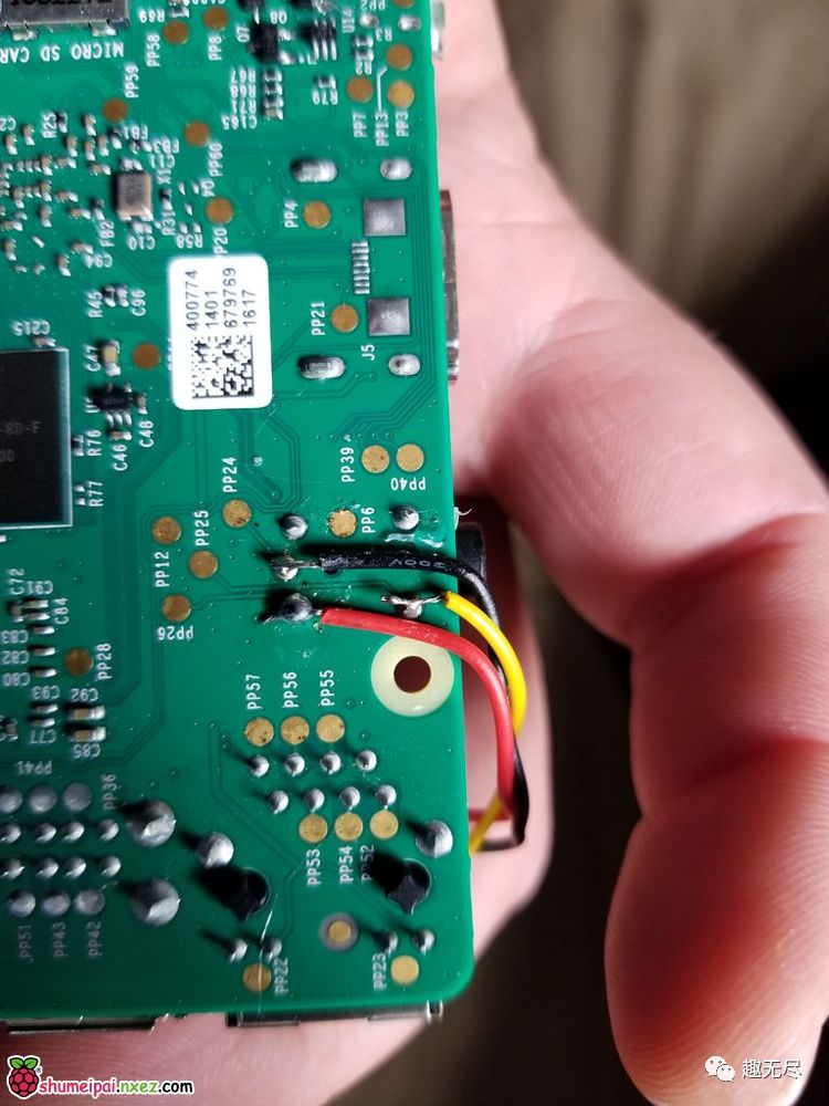
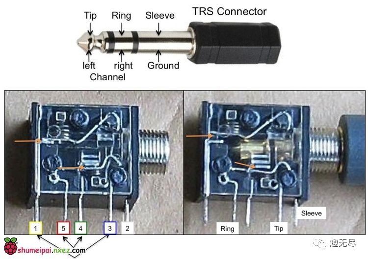
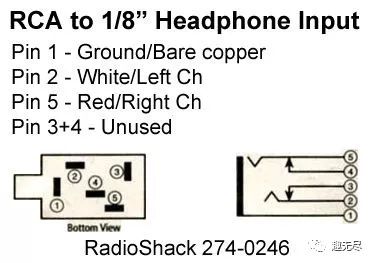
Soldering the audio interface (pins shown above): Remove the red wire from the Raspberry Pi and solder it to pin 2 of the 1/8 jack. Remove the yellow wire from the Raspberry Pi and solder it to pin 5 of the 1/8 jack. Remove the black wire and twist an 8-10 cm long black wire, then solder it to pin 1 of the 1/8 jack. Solder the 8-10 cm long red wire to pin 3 of the 1/8 jack. You should now have an audio interface connected to the Raspberry Pi, and when you play sound and plug in your ear, you will hear it clearly. I recommend fixing the wires with hot glue at the bottom of the Raspberry Pi while the bottom interface can hold the fine wires and protect them from damage and short circuits.

Step 3: Solder the Power Board and Switch
PowerBoost 1000C meets all your lithium charging needs.
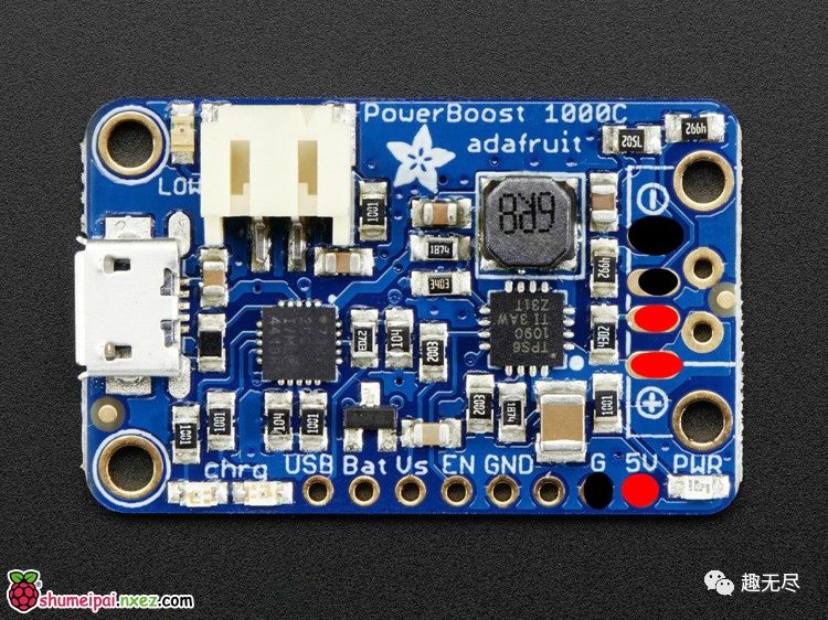
However, unfortunately, this little thing, while great, does not output enough power to run the Pi-Switch. But it is indeed a very nice charging battery, which provides enough power for the Raspberry Pi to power the screen and audio for about 2-3 hours. I will keep the power on to drain the battery, which means you need to plug it directly into the power supply. I’m still working on finding a better solution.
Power wires: First look at the image above; you will notice 3 black circles and 3 red circles. You guessed it! Solder 3 25 cm black wires and 3 25 cm red wires to the corresponding positions marked on the PowerBoost.
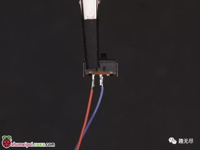
Switch (power switch, not Nintendo): Cut one leg from the switch on the right or left side and solder a 5 cm wire to the remaining pin of the broken power switch. Solder one of the wires to PowerBoost, and the remaining wire connects to the PowerBoost board. Hot glue is cheap, quick, and easy. I recommend applying hot glue to each wire connected to the Power Boosted Board.
Step 4: Speakers and Audio Board and Headphone Jack (Connect Them Together)
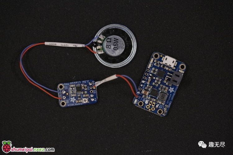
In this step, we will combine these components together.
Solder the speakers: As shown, solder each wire to each pad on the speaker. Heat shrink is so convenient if you, like me, love using hot glue!
Solder the audio board: Pick up your PAM8302 and check the instructions. As shown, on the 4-8 ohm side of the circuit board, solder the speaker wires to the two center pads.
Solder the power for audio: Remove one of the red power wires from the PowerBoost and a ground board, and solder the red wire to the vin on the PAM8302 and the black wire to the gnd on the PAM8302.
Solder the headphones to PAM8302: Take the red wire from the headphone jack and solder it to A+ on the PAM8302. Take the black wire from the headphone jack and solder it to A- on the PAM8302.
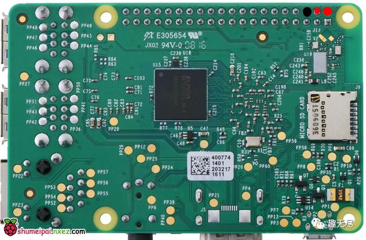
Solder to the Raspberry Pi: Here is a picture of the Raspberry Pi. Remove a black wire from the PowerBoost and solder it to the black dot on the Raspberry Pi picture. Remove a red wire from the PowerBoost and solder it to the red dot on the Raspberry Pi picture.
Testing: Please be careful to ensure the remaining black wire comes from the PowerBoost, and that the red wire from the PowerBoost does not touch anything. Then install the battery and flip the switch. If all components are correctly connected, the indicator light on the charging board should light up, and if the speaker noise is too loud, you might hear a slight buzzing from the speaker, indicating a possible soldering issue.
Step 5: Assembly
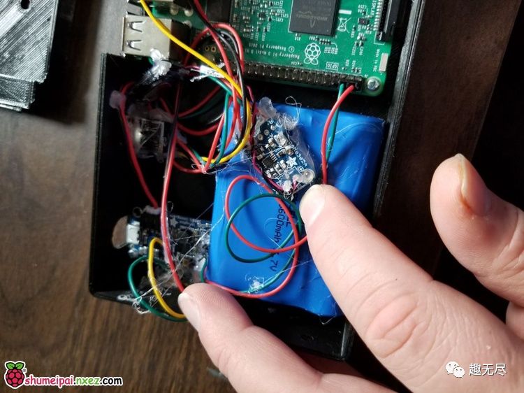
Other than the LCD and optional Pi camera, we should have installed everything by now. In the previous images, you can see how to embed the Raspberry Pi itself. This is very simple; now you can take out that 80-piece assorted laptop replacement screw kit, find screws that are 1-2 mm thicker than the Raspberry Pi, and screw them into the soft printed plastic. PLA is recommended. There should be two suitable clips to secure the Raspberry Pi, and there are holes in the opposite corners for threading wires. The power board is the same. The images above show the assembly of the power board.
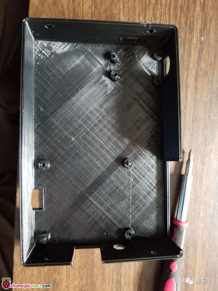
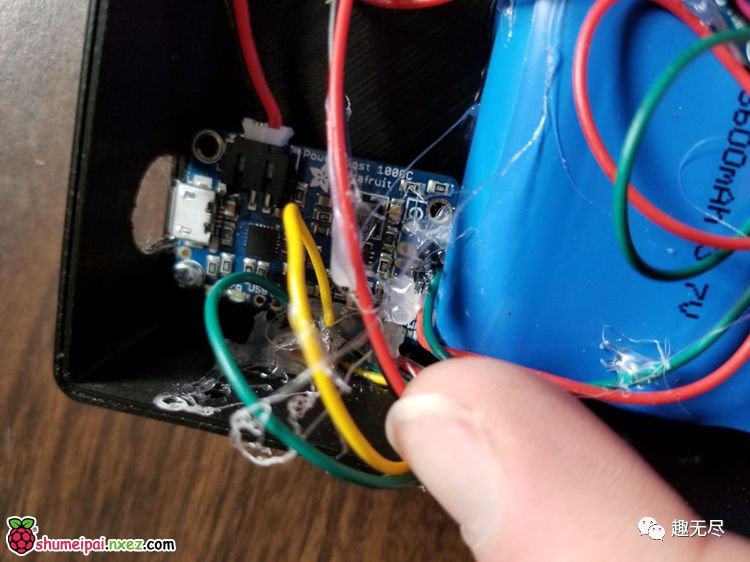
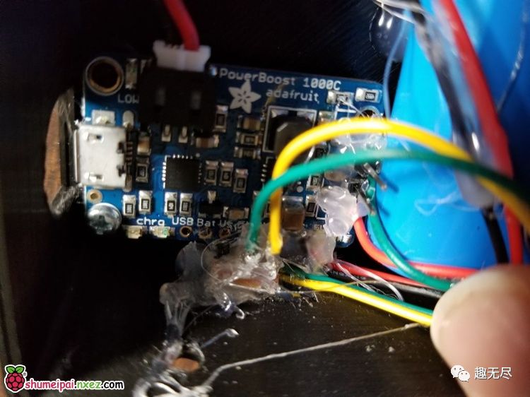
Now pass the switch through the small hole above the power board. Use tweezers or your fingers to grab the switch from the outside. As shown, gently pull the switch to prevent it from falling into the box, and place some hot glue on the back of the switch. Once the glue cools, check that the switch is easy to use. If the glue is not good, please try again. Drill a 3/16 inch hole between the Raspberry Pi and the PowerBoost, or just drill a hole. It should be on the side of the Raspberry Pi’s USB port. Pass the headphone jack through the hole and glue it in place. Finally, glue the speaker battery and audio board in place, as shown above. I placed the speaker under the plastic below the battery, and I directly stuffed it behind the PowerBoost board. Then, I glued the battery to the sides of the 3D printed case. Finally, I glued the speaker amplifier to the top of the battery.
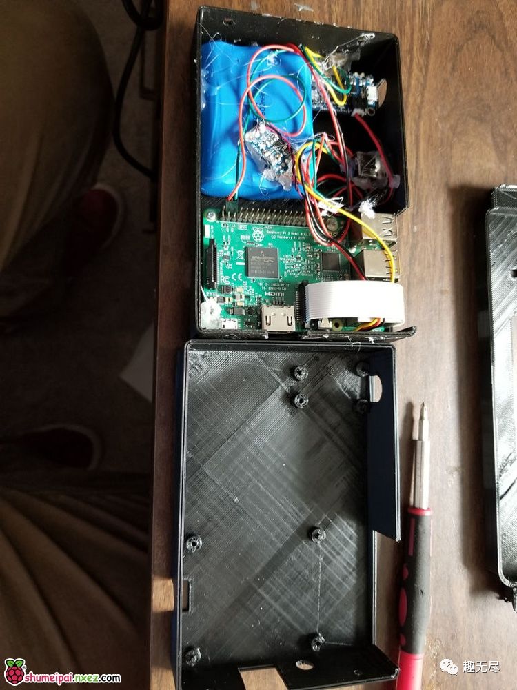
So, if you have done all this, you should now have the Raspberry Pi, PowerBoost, PAM8302, speakers, power switch, and battery installed on the back of the Raspberry Pi box. Additionally, there should be a 25 cm black wire and a 25 cm red wire left.
Step 6: Add Screen and Accessories
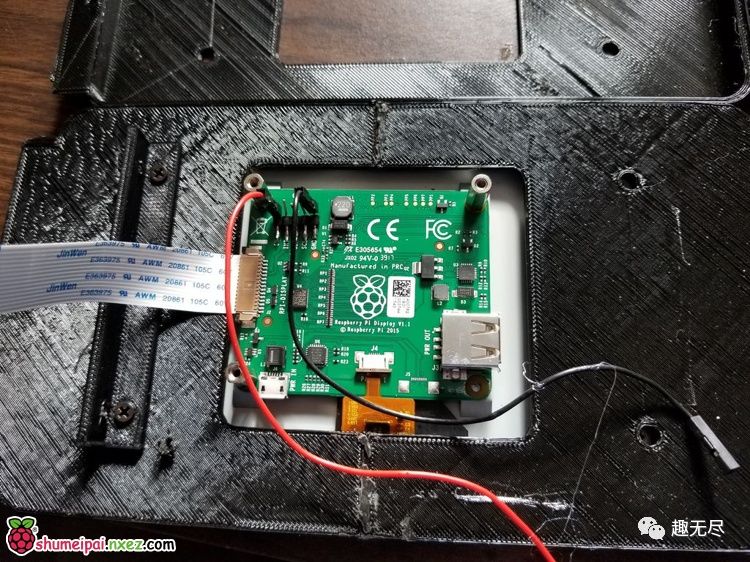
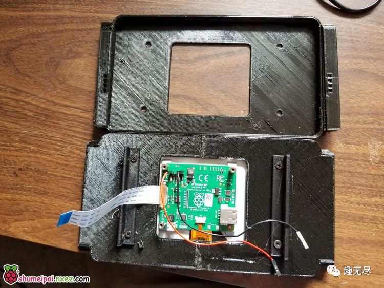
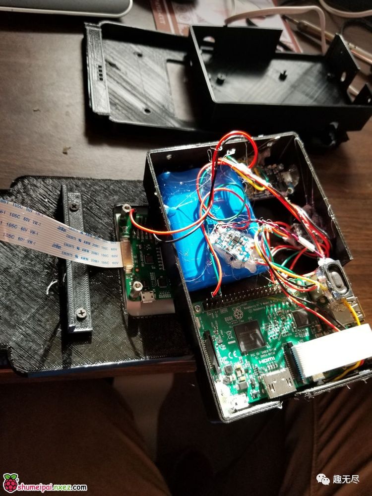
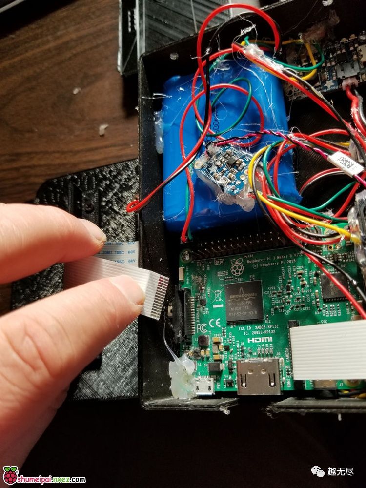
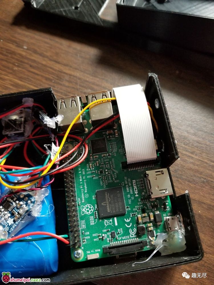
You are almost done with this quite complex assembly. Now take some 6 mm long screws and threaded side rods, as shown in the image, and screw them into the screw holes on the screen. If the screen is not aligned, you may need to flip it for better use. Looking at the picture, you may notice that my molding line connects to my screen. In fact, I placed the pin header on my PowerBoost instead of soldering it directly. If you didn’t look at these steps in advance, you might be soldering wires. If I don’t specifically remind you, I prefer pin headers because they allow for quick and easy modifications, and my creations are always in a state of flux.
Using the Remaining Wires: Solder the remaining red wire from the PowerBoost to the vin pin on the screen. Solder the remaining black wire from the PowerBoost to the gnd pin on the screen.
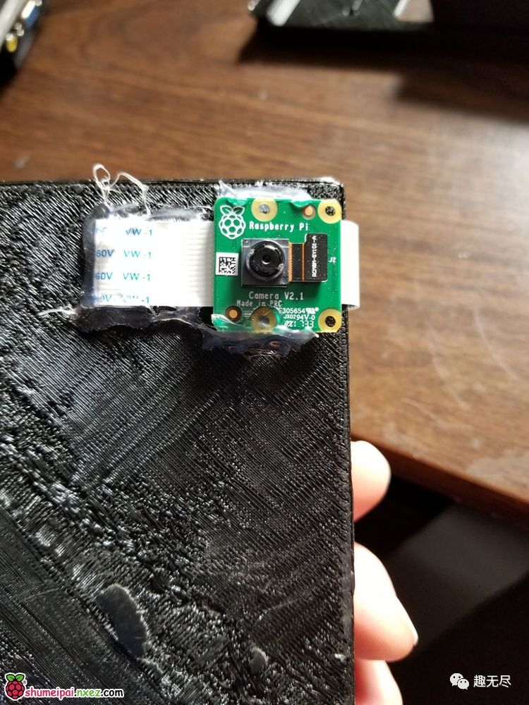
Connect the Camera (Optional): Insert the camera cable into the camera board. As shown, insert the cable into the Raspberry Pi. Flip the camera through the Ethernet jack. Flatten the cable and glue it in place.
Add Screen Ribbon Cable: As shown, insert the ribbon cable into the Raspberry Pi. If you look at the image above, it shows how I flipped the back panel down into place after connecting the ribbon cable. Finally, screw the four screws on the back panel into the bracket on the back of the screen, and fully assemble.
Step 7: Create Raspberry Pi Software Image
Step 1) Connect a keyboard to the Raspberry Pi and power it on. Go to this website and follow the installation steps: (just set your keyboard as a temporary controller) https://github.com/RetroPie/RetroPie-Setup/wiki/First-Installation
Step 2) You may hear an annoying buzzing sound (which can be ignored for now; we will fix it soon). Follow these steps to set up wifi through the RetroPie menu: RetroPie / settings > raspi-config > interfacing options > SSH > Yes > Ok > Finish > Retropie Setup > Configuration Tools > wifi > (set your wifi) > exit >
Step 3) Install Pixel: raspbiantools > Install Pixel Desktop Environment > yes > (wait a moment) > ok (to flash player) > (wait a little longer) > ok > cancel > back >
Step 4) Install Kodi: Manage Packages > Manage Optional Packages > Kodi > Install from binary > (wait a while) > back > back > back >
Step 5) Register and connect your JoyCons:
Configuration /Tools > bluetooth > Register and Connect (press the small button between L and R on the right joy-con) > choose Joy-Con (R) > NoInputNoOutput > (wait) > ok > ok
Step 6) Repeat Step 5 with Joy-Con (L).
Step 7) cancel > back > exit > (start button) > quit > quit emulation station > yes
Step 8) Run the following command:
sudo apt-get update && sudo apt-get upgrade && sudo rpi-update
sudo reboot
Step 9) Enter the following:
wget https://raw.githubusercontent.com/cfoote7/PiSwitch/master/setup.sh
sudo chmod 777 setup.sh && sudo chmod a+x setup.sh
./setup.sh
Update: I have added a controller connection menu that will display on the screen whether connected to two joy-cons. Also added a single-player/multi-player mode selection menu. Upon completing the first boot, you will be able to connect your controller using the “+” and “-” buttons, click next, click RetroPie, and select single-player mode.
Note: pywx.py is my touchscreen startup selection menu; it is not actually a startup option, all these options are stored under Raspbian Jessie. I plan to add a simpler way to pair the controller with this menu on startup. Please stay tuned for updates. If you make any improvements, please pay special attention to whether you can build this feature and let me know. I would be very happy to collaborate on this. Please check my repository; I will update it at https://github.com/cfoote7/PiSwitch
via Cherry Translated.
For text links in the article, please click [Read Original] to view
Submission: [email protected]
