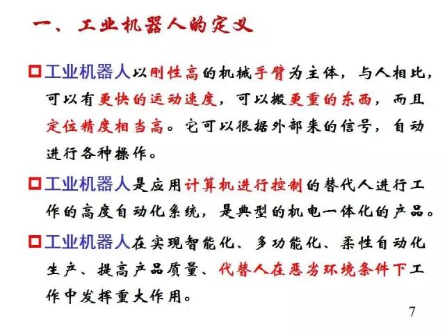
Robots have become increasingly popular and valued in recent years. Many traditional industries are now introducing industrial robots into their production processes. With the improvements and optimizations in robot technology, the importance of industrial robots in traditional manufacturing has become more evident.
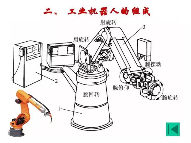
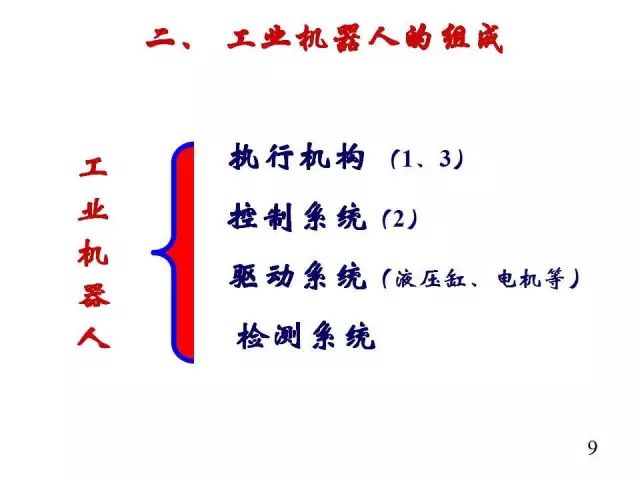
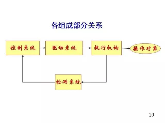
So, what is an industrial robot? What does its internal structure look like? ….. After reading this article, you will have a systematic and comprehensive understanding of industrial robot technology!
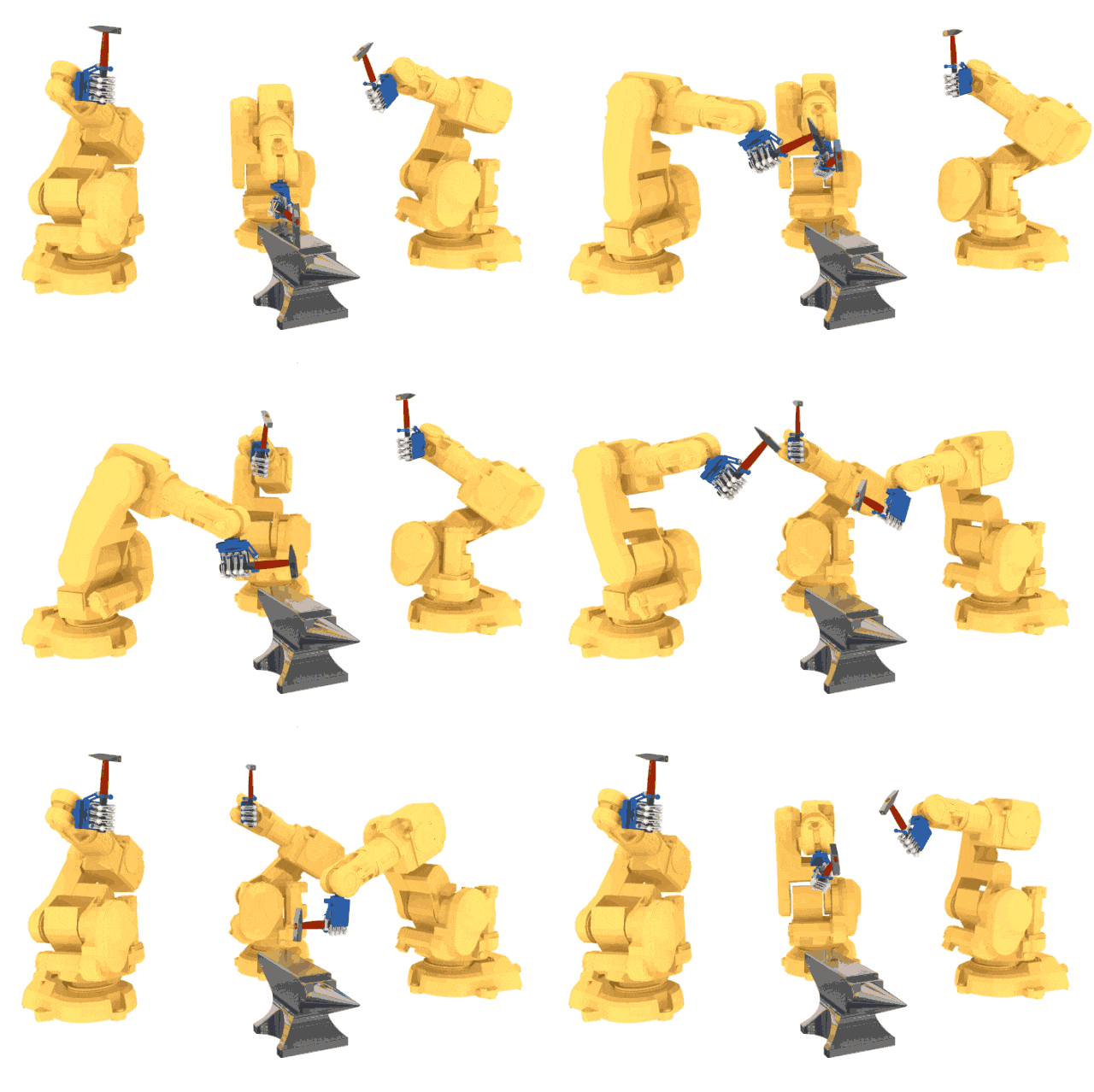
Industrial Robot Popularization
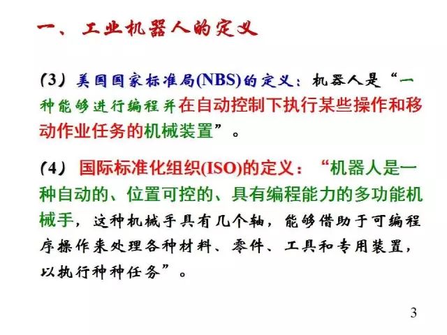

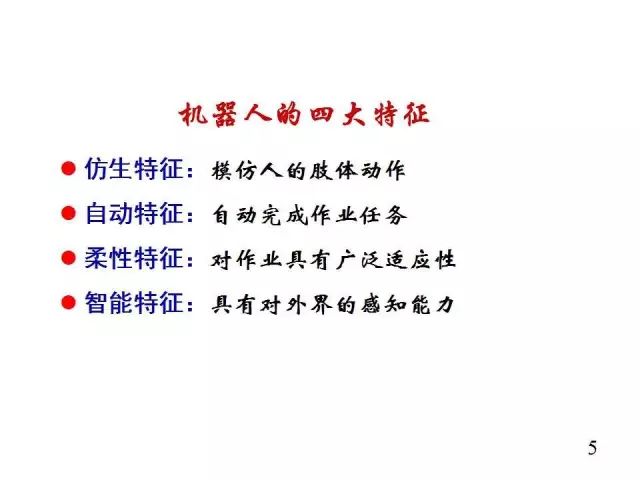
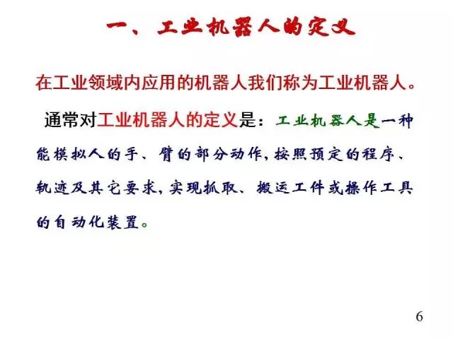

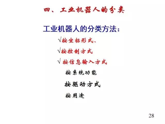
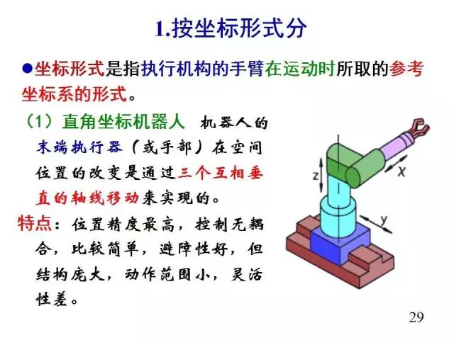
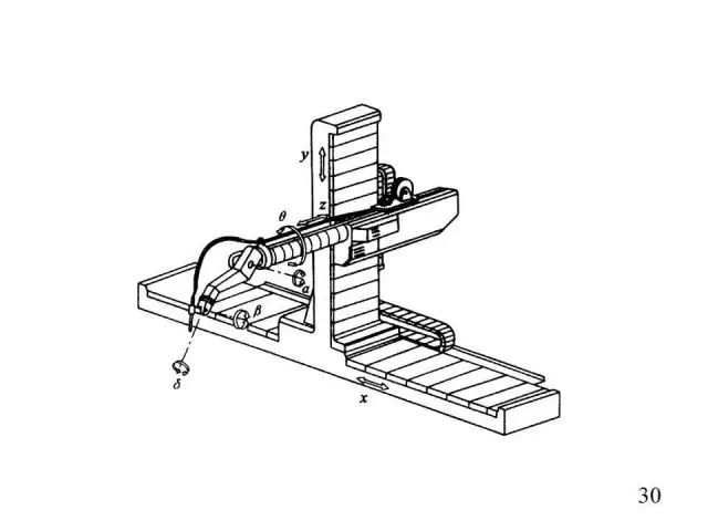
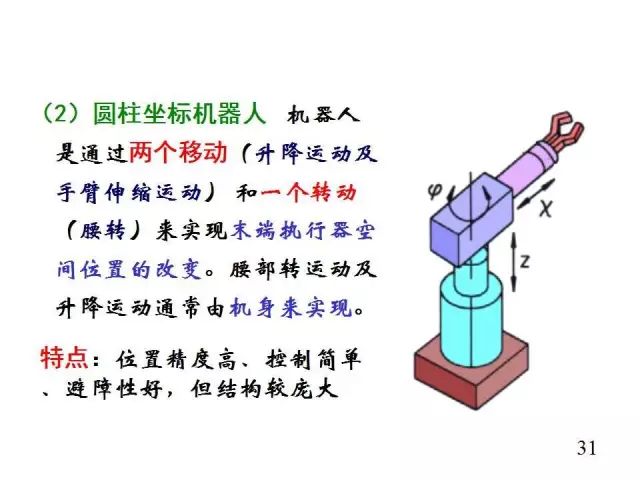
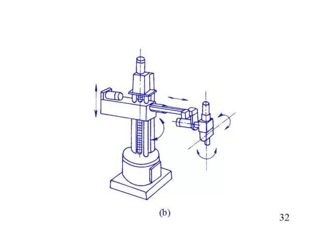
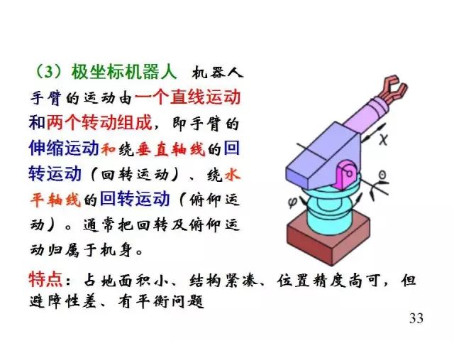
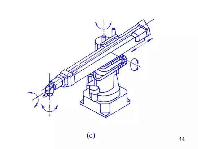
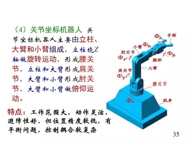
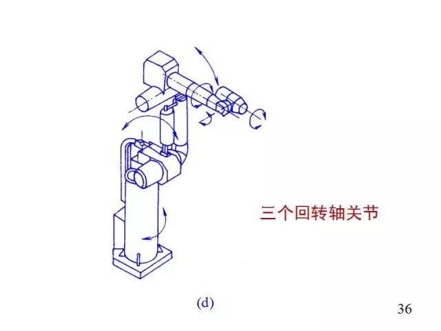
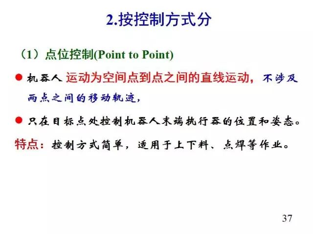
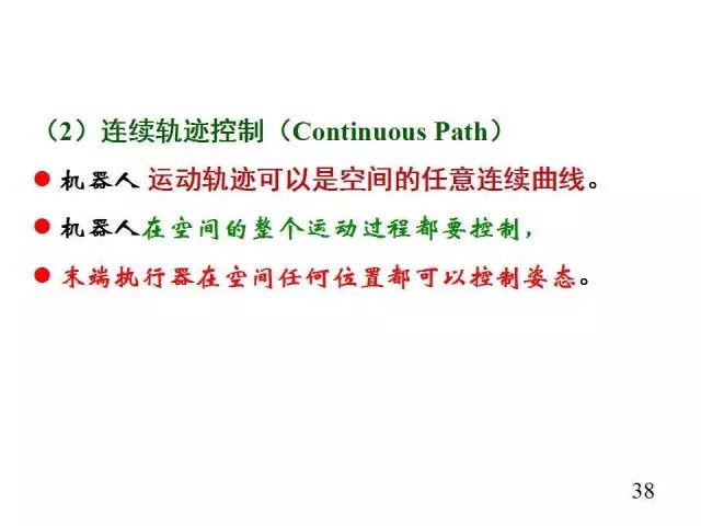
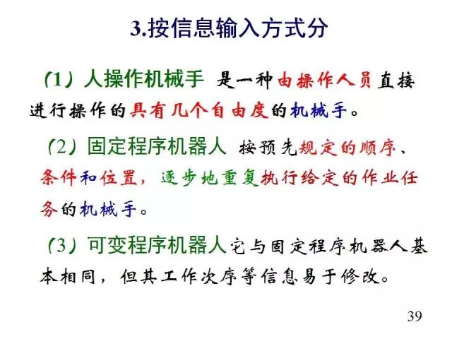
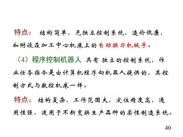
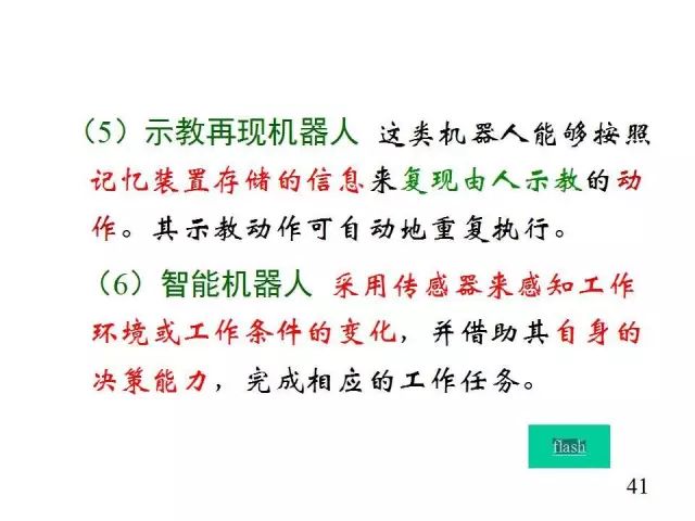
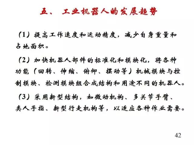
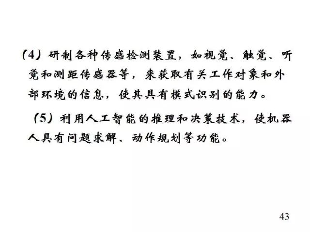

Classification of Industrial Robots
Mobile Robots
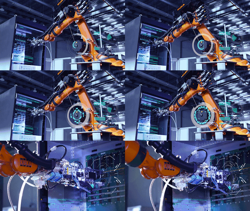
Mobile robots (AGVs) are a type of industrial robot widely used for flexible handling and transportation in industries such as machinery, electronics, textiles, tobacco, medical, food, and paper. They are also used in automated warehouses, flexible processing systems, and flexible assembly systems (with AGVs as mobile assembly platforms); they can also serve as transport tools in sorting items at stations, airports, and post offices.
Spot Welding Robots
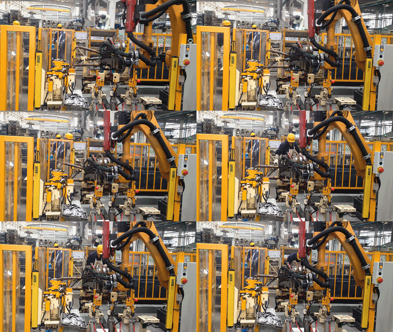
Welding robots are characterized by stable performance, large working space, high motion speed, and strong load capacity. The welding quality is significantly better than manual welding, greatly improving the productivity of spot welding operations.
Arc Welding Robots
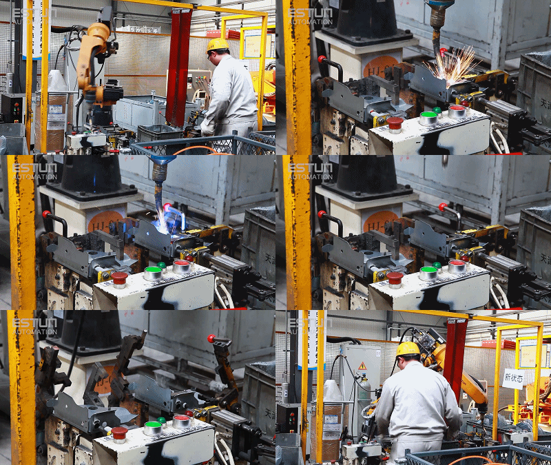
Arc welding robots are mainly used in the welding production of various automotive parts. In this field, large international industrial robot manufacturers primarily provide unit products to complete equipment suppliers.
Laser Processing Robots
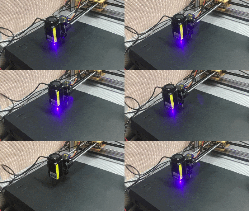
Laser processing robots apply robot technology to laser processing, achieving more flexible laser processing operations through high-precision industrial robots. The system can operate online or be programmed offline.
Robots automatically detect the workpiece during processing, generate a model of the processed piece, and then create processing curves. CAD data can also be used for direct processing. They can be used for laser surface treatment, drilling, welding, and mold repair of workpieces.
Vacuum Robots
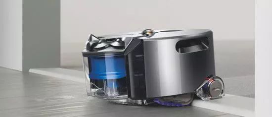
Vacuum robots operate in a vacuum environment, primarily used in the semiconductor industry for the transport of wafers within vacuum chambers. Vacuum manipulators are difficult to import, restricted, used in large quantities, and have strong universality, becoming a key component that limits the research and development progress of semiconductor equipment and the competitiveness of complete machine products.
Clean Robots
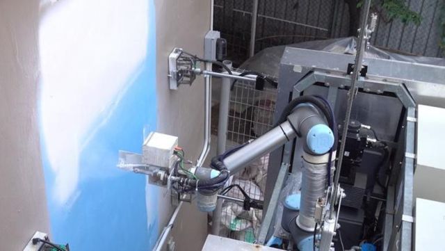
Clean robots are industrial robots used in clean environments. As production technology levels continue to improve, the requirements for production environments are becoming increasingly stringent. Many modern industrial products require production in clean environments, making clean robots essential equipment for production in such conditions.
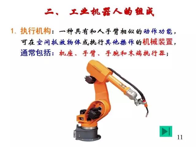
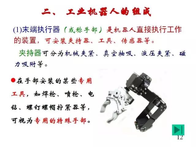
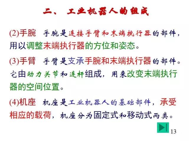
Internal Structure of Industrial Robots
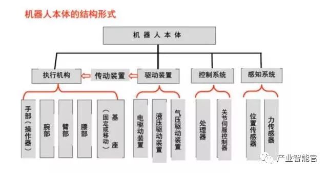
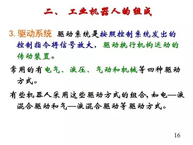
1. Robot Drive System
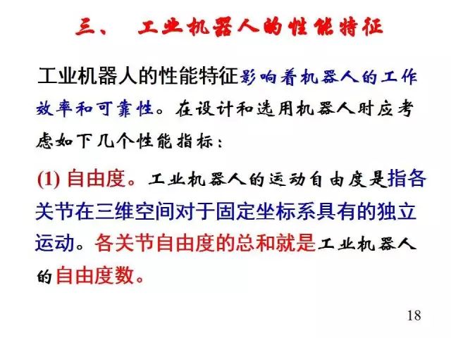
Concept: To make a robot operate, it is necessary to install a transmission device at each joint, that is, each degree of freedom. Function: Provides the driving force for the actions of various parts and joints of the robot.
Drive systems can be hydraulic, pneumatic, electric, or a combination of these; they can be direct drive or indirect drive through mechanical transmission mechanisms such as synchronous belts, chains, gear systems, or harmonic gears.
1. Electric Drive System
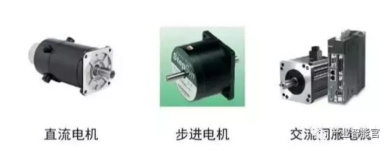
Electric drive systems have simple energy requirements, a wide range of speed variations, high efficiency, and high speed and position accuracy. However, they are often linked with reduction devices, making direct drive more difficult.
Electric drive systems can be divided into DC (direct current), AC (alternating current) servo motor drives, and stepper motor drives. Brushed DC servo motors are prone to wear and spark formation. Brushless DC motors are becoming increasingly widely used. Stepper motor drives are often open-loop controlled, simple to control but with low power, typically used in low-precision, low-power robot systems.
Before powering on the electric drive, the following checks should be made:
1) Is the power supply voltage appropriate (overvoltage can easily damage the drive module)? Ensure the +/- polarity for DC input is not reversed, and check if the motor model or current setting on the drive controller is appropriate (do not set it too high initially);
2) Ensure control signal lines are securely connected; in industrial settings, consider shielding (e.g., using twisted pair cables);
3) Do not connect all necessary wires at the start; only connect the basic system. Once it operates well, gradually connect additional components.
4) Be clear about the grounding method; use floating ground if applicable.
5) Closely monitor the motor’s status during the first half-hour of operation, checking for normal movement, noise, and temperature rise. If issues are found, stop and adjust immediately.
2. Hydraulic Drive
Hydraulic systems achieve linear motion through high-precision cylinders and pistons, with relative motion between the cylinder and piston rod.Advantages: High power, can eliminate reduction devices by connecting directly to the driven rod, compact structure, good rigidity, quick response, and high precision in servo drives.Disadvantages: Requires a hydraulic source, prone to fluid leakage, and not suitable for extreme temperatures; thus, hydraulic drives are mainly used in very high-power robot systems.Select suitable hydraulic oil. Prevent solid impurities from entering the hydraulic system, and avoid air and water intrusion into the hydraulic system. Mechanical operations should be smooth and gentle to avoid shock loads that can lead to frequent mechanical failures and greatly shorten service life. Pay attention to cavitation and overflow noise. During operation, always monitor the sounds of the hydraulic pump and overflow valve. If the hydraulic pump produces a “cavitation” noise that cannot be eliminated after venting, the cause must be identified and rectified before use. Maintain suitable oil temperatures; the working temperature of hydraulic systems should generally be controlled between 30-80°C.
3. Pneumatic Drive
Pneumatic drives have a simple structure, are clean, and have quick action with cushioning effects. However, compared to hydraulic drives, they have lower power, poor rigidity, and high noise levels, and speed control is difficult, so they are often used in robots with low precision for point control.
(1) They are characterized by fast speed, simple system structure, easy maintenance, and low cost, making them suitable for medium and small load robots. However, due to difficulties in achieving servo control, they are mostly used in program-controlled robots, such as loading and unloading or stamping robots.
(2) In most cases, they are used for two-position or limited point control in medium and small robots.
(3) Most control devices currently use programmable controllers (PLC controllers). In flammable and explosive environments, pneumatic logic elements can be used to form control devices.
2. Linear Transmission Mechanism
The transmission device is a key part connecting the power source and the moving link. Depending on the type of joints, common transmission mechanisms include linear and rotary transmission mechanisms.
Linear transmission methods can be used for X, Y, and Z-axis drives in Cartesian robots, radial drives in cylindrical coordinate structures, and vertical lift drives, as well as radial telescopic drives in spherical coordinate structures.
Linear motion can be achieved by converting rotational motion into linear motion through transmission elements such as gears and racks or screw nuts, or it can be driven directly by linear drive motors or the pistons of cylinders or hydraulic cylinders.
1. Gear Rack Device
Typically, the rack is fixed. The rotational motion of the gear is converted into linear motion of the support plate.
Advantages: Simple structure.
Disadvantages: Large backlash.
2. Ball Screw
Ball screws have balls embedded in the helical grooves of the screw and nut, allowing the balls to circulate continuously through the guiding grooves in the nut.
Advantages: Low friction, high transmission efficiency, no crawling, and high precision;
Disadvantages: High manufacturing costs and complex structure.
Self-locking issue: Theoretically, ball screw pairs can also be self-locking, but in practical applications, this feature is rarely used due to reliability issues or high processing costs; since the diameter-to-lead ratio is very large, a set of worm gear or similar self-locking device is usually added.
3. Rotary Transmission Mechanism
The purpose of using rotary transmission mechanisms is to convert the high rotational speed output by the motor into lower rotational speed while obtaining greater torque. Common rotary transmission mechanisms in robots include gear chains, synchronous belts, and harmonic gears.
1. Gear Chain
(1) Speed relationship
(2) Torque relationship
2. Synchronous Belt
Synchronous belts are belts with many shaped teeth that mesh with similarly toothed synchronous pulleys. When working, they function like soft gears.
Advantages: No slippage, good flexibility, low cost, and high repeat positioning accuracy.
Disadvantages: They exhibit some elastic deformation.
3. Harmonic Gear
Harmonic gears consist of three main components: rigid gears, harmonic generators, and flexible gears, with the rigid gear typically fixed and the harmonic generator driving the flexible gear to rotate.
Main features:
(1) Large transmission ratio, typically 50-300 for a single stage.
(2) Smooth transmission with high load capacity.
(3) High transmission efficiency, reaching 70%-90%.
(4) High transmission accuracy, 3-4 times higher than ordinary gear transmission.
(5) Small backlash, less than 3’.
(6) Cannot obtain intermediate outputs; the flexible wheel has lower rigidity.
Harmonic transmission devices have been widely used in countries with advanced robot technology. In Japan, for example, 60% of robot drive devices use harmonic transmission.
Robots sent to the moon by the United States used harmonic transmission devices in all joint parts, with one arm utilizing 30 harmonic transmission mechanisms.
The Soviet Union’s lunar rover “Lunokhod” used eight wheels, each driven by a closed harmonic transmission mechanism. Robots developed by Volkswagen in Germany and Renault in France also utilize harmonic transmission mechanisms.
4. Robot Sensor System
1. The sensing system consists of internal sensor modules and external sensor modules to obtain meaningful information about the internal and external environmental states.
2. The use of intelligent sensors enhances the robot’s mobility, adaptability, and intelligence level.
3. Intelligent sensors improve the robot’s mobility, adaptability, and intelligence level.
4. For some specific information, sensors are more effective than human sensory systems.
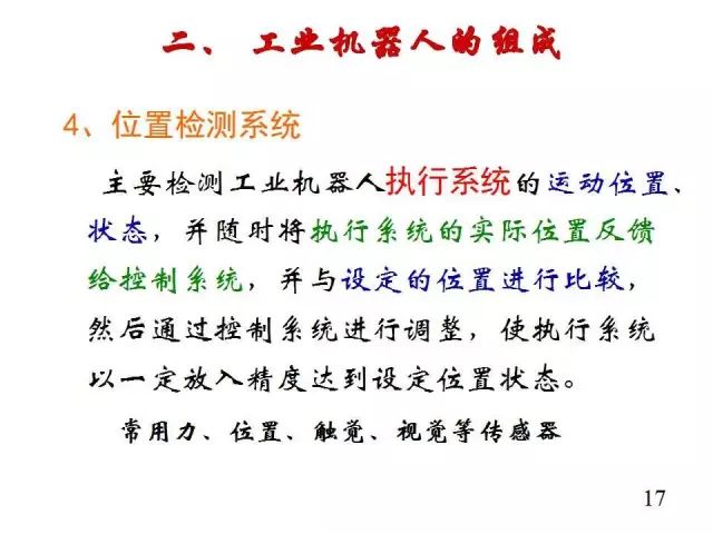
5. Robot Position Detection
Rotary optical encoders are the most commonly used position feedback devices. Photoelectric detectors convert light pulses into binary waveforms. The angle of the axis is obtained by counting the number of pulses, with the rotation direction determined by the relative phase of two square wave signals.
Inductive synchronizers output two analog signals—the sine and cosine signals of the axis’s rotation angle. The axis’s rotation angle is calculated from the relative amplitudes of these two signals. Inductive synchronizers are generally more reliable than encoders, but they have lower resolution.
Potentiometers are the most direct form of position detection. They are connected in a bridge and can generate a voltage signal proportional to the axis’s rotation angle. However, they have low resolution, poor linearity, and are sensitive to noise.
Speedometers can output an analog signal proportional to the axis’s speed. If such speed sensors are unavailable, velocity feedback signals can be obtained by differentiating the detected position relative to time.
6. Robot Force Detection
Force sensors are typically installed in three positions on the operation arm:
1. Installed on the joint driver, measuring the torque or force output of the driver/reducer itself. However, they cannot effectively detect the contact force between the end effector and the environment.
2. Installed between the end effector and the terminal joint of the operation arm, referred to as wrist force sensors. They typically measure three to six force/torque components applied to the end effector.
3. Installed at the “fingertips” of the end effector. These force-sensitive fingertips often contain strain gauges to measure one to four components of force applied to the fingertips.
7. Robot-Environment Interaction System
1. The robot-environment interaction system is designed to realize the connection and coordination between industrial robots and external equipment in the environment.
2. Industrial robots are integrated with external devices into functional units, such as processing and manufacturing units, welding units, assembly units, etc. They can also be integrated into multiple robots, machine tools, or storage devices to execute complex tasks.
8. Human-Robot Interaction System
The human-robot interaction system allows operators to participate in robot control and communicate with the robot. This system can be broadly divided into two categories: command input devices and information display devices.
Knowledge Related to Robot Control Systems
What is a Robot Control System?
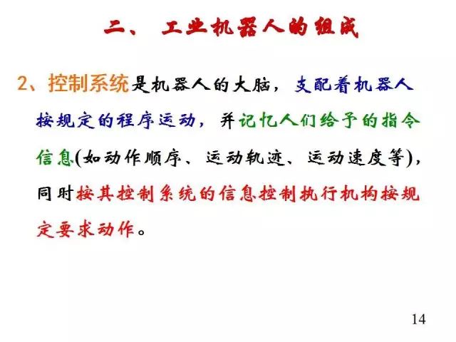
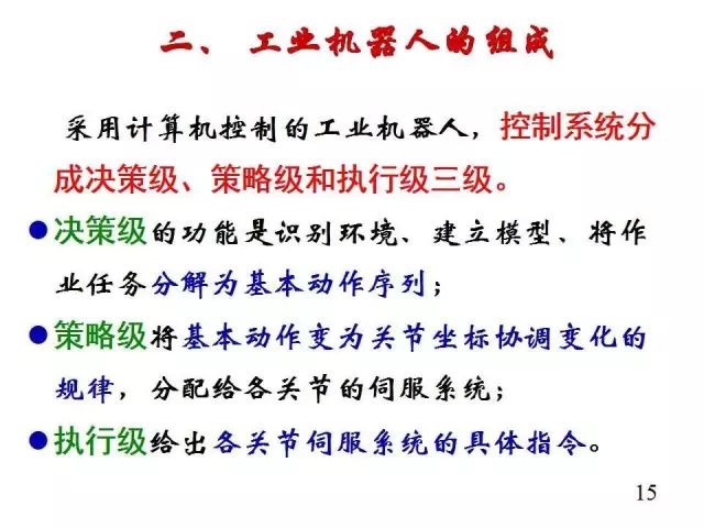
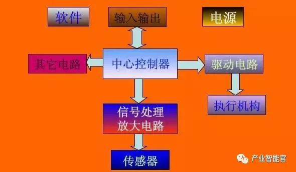
Just having sensors and muscles does not allow human limbs to move. On one hand, the signals from the senses have no organs to receive and process them; on the other hand, there are no organs to send neural signals that drive muscle contraction or relaxation. Similarly, if a robot only has sensors and actuators, the robotic arm cannot function normally. The reason is that the signals output by the sensors do not take effect, and the drive motors do not receive the driving voltage and current, so a controller is needed to form a control system composed of hardware and software.
The function of the robot control system is to receive detection signals from sensors and, according to the operational task requirements, drive the motors in the robotic arm just as human activities rely on sensory input. Robot motion control cannot be separated from sensors, which are used to detect various states. The internal sensor signals of the robot reflect the actual motion state of the robotic arm joints, while the external sensor signals are used to detect changes in the working environment.
Thus, the combination of the robot’s nerves and brain forms a complete robot control system.
What aspects does the robot motion control system include?
Actuators—servo motors or stepper motors;
Drive mechanisms—servo or stepper drivers;
Control mechanisms—motion controllers that perform path and motor linkage algorithm calculations;
Control methods—if there are fixed execution action modes, then a program with fixed parameters is prepared for the motion controller; if there are visual systems or other sensors, then a program with non-fixed parameters is prepared based on sensor signals for the motion controller.
Basic Functions of Robot Control Systems
-
Control the motion position of the end effector of the robotic arm (i.e., control the points and moving paths the end effector passes through);
-
Control the motion posture of the robotic arm (i.e., control the relative position of adjacent moving components);
-
Control the motion speed (i.e., control the pattern of change in the motion position of the end effector over time);
-
Control the motion acceleration (i.e., control the change in speed during the motion process);
-
Control the output torque of each power joint in the robotic arm (i.e., control the force applied to the object being operated);
-
Provide convenient human-robot interaction functions, allowing the robot to complete specified tasks through memory and reproduction;
-
Enable the robot to have detection and sensory functions for the external environment. Industrial robots are equipped with sensors for vision, force, touch, etc., to measure, identify, and judge changes in operating conditions.
Industrial Robot Control System
1. Hardware Structure of Industrial Robot Control Systems
The controller is the core of the robot system, and foreign companies have implemented strict restrictions on our country. In recent years, with the development of microelectronics technology, the performance of microprocessors has increased while their prices have decreased. Currently, 32-bit microprocessors are available on the market for $1-2. The high cost-performance ratio of microprocessors has brought new development opportunities for robot controllers, making it possible to develop low-cost, high-performance robot controllers. To ensure the system has sufficient computing and storage capabilities, most robot controllers now use chips with stronger computing capabilities, such as ARM series, DSP series, POWERPC series, Intel series, etc.
Moreover, existing general-purpose chips do not completely meet the requirements of certain robot systems regarding price, performance, integration, and interfaces. This has led to the demand for SoC (System on Chip) technology in robot systems, which integrates specific processors with required interfaces, simplifying the design of peripheral circuits, reducing system size, and lowering costs. For example, Actel has integrated the NEOS or ARM7 processor cores into its FPGA products to form a complete SoC system. In the field of robot motion controllers, research is mainly focused in the United States and Japan, with mature products available, such as those from DELTATAU in the United States and POMI in Japan. Their motion controllers are based on DSP technology and adopt an open structure based on PC.
2. Architecture of Industrial Robot Control Systems
In terms of controller architecture, research focuses on the division of functions and the norms of information exchange between functions. In the research of open controller architectures, two basic structures exist: one is based on hardware-level division, which is relatively simple. In Japan, architectures are structured based on hardware, such as Mitsubishi Heavy Industries dividing the structure of their PA210 portable general-purpose intelligent robotic arm into five layers; the other is based on functional division, which considers both hardware and software and is a direction for research and development of robot controller architectures.
3. Development Environment for Control Software
In terms of robot software development environments, many industrial robot companies have their own independent development environments and programming languages, such as Japan’s Motoman, Germany’s KUKA, the United States’ Adept, and Sweden’s ABB. Many universities have conducted extensive research on robot development environments (Robot Development Environment), providing many open-source solutions that can be integrated and controlled under certain robot hardware structures, with many relevant experiments conducted in laboratory environments. Existing robot system development environments include TeamBots v.2.0e, ARIA v.2.4.1, Player/Stage v.1.6.5.1.6.2, Pyro v.4.6.0, CARMEN v.1.1.1, MissionLab v.6.0, ADE v.1.0beta, Miro v.CVS-March17.2006, MARIE v.0.4.0, FlowDesigner v.0.9.0, RobotFlow v.0.2.6, etc. From the perspective of robot industry development, there are two demands for robot software development environments. On one hand, there are demands from end users of robots who not only use robots but also wish to program them to endow them with more functions, often using visual programming languages, such as the graphical programming environment of LEGO MindStorms NXT and the visual programming environment provided by Microsoft Robotics Studio.
4. Robot-Specific Operating Systems
(1) VxWorks is an embedded real-time operating system (RTOS) designed and developed by Wind River in 1983, which is a key component of the Tornado embedded development environment. VxWorks features a customizable microkernel structure; efficient task management; flexible inter-task communication; microsecond-level interrupt handling; support for the POSIX 1003.1b real-time extension standard; and support for various physical media and standard complete TCP/IP network protocols.
(2) Windows CE has good compatibility with the Windows series, which is undoubtedly a significant advantage for promoting Windows CE. Windows CE provides a rich operating system platform for building dynamic applications and services for handheld and wireless devices. It can run on various processor architectures and is usually suitable for devices with certain limitations on memory usage.
(3) Embedded Linux, due to its open-source nature, allows users to modify it as needed. Most of it follows the GPL, is open-source, and free. It can be slightly modified for application in users’ own systems. There is a large developer community, and it does not require specialized talent; anyone familiar with Unix/Linux and C language can use it. The number of supported hardware is vast. Embedded Linux is essentially no different from ordinary Linux, with most hardware used on PCs also supported by embedded Linux. Moreover, drivers for various hardware can be easily obtained, greatly facilitating the writing of proprietary drivers for users’ specific hardware.
(4) μC/OS-Ⅱ is a well-known open-source real-time kernel designed for embedded applications, suitable for 8-bit, 16-bit, and 32-bit microcontrollers or digital signal processors (DSPs). Its main features include open-source code, good portability, solidification, modularity, priority-based kernel, and determinism.
(5) DSP/BIOS is a real-time multitasking operating system kernel designed specifically for TI’s TMS320C6000TM, TMS320C5000TM, and TMS320C28xTM series DSP platforms. It consists of three parts: a multithreaded real-time kernel, real-time analysis tools, and a chip support library. Using a real-time operating system for development allows for the convenient and rapid development of complex DSP programs.
5. Robot Servo Communication Bus Technology
Currently, there is no dedicated servo communication bus for robot systems internationally. In practical applications, commonly used buses, such as Ethernet, CAN, 1394, SERCOS, USB, and RS-485, are typically used based on system requirements. Most current communication control buses can be categorized into two types: serial bus technology based on RS-485 and line driver technology, and high-speed serial bus technology based on real-time industrial Ethernet.
Intelligent Robot Control Systems
(1) Open modular control system architecture: A distributed CPU computer structure is used, divided into a robot controller (RC), motion controller (MC), opto-isolated I/O control board, sensor processing board, and programming teaching box. The robot controller (RC) and programming teaching box communicate via serial/CAN bus. The main computer of the robot controller (RC) completes motion planning, interpolation, and position servo, as well as main control logic, digital I/O, and sensor processing functions, while the programming teaching box displays information and inputs commands.
(2) Modular hierarchical controller software system: The software system is built on a real-time multitasking operating system based on open-source Linux, adopting a layered and modular structure design to ensure the openness of the software system. The entire controller software system is divided into three levels: hardware driver layer, core layer, and application layer. Each level addresses different functional requirements and corresponds to different levels of development, with several functionally opposing modules within each level working together to achieve the functions provided by that level.
(3) Robot fault diagnosis and safety maintenance technology: Diagnosing robot faults through various information and performing corresponding maintenance is a key technology to ensure the safety of robots.
(4) Networked robot controller technology: Currently, robot application engineering is evolving from single robot workstations to robotic production lines, making networking technology for robot controllers increasingly important. Controllers are equipped with serial, field bus, and Ethernet networking functions. This facilitates communication between robot controllers and between robot controllers and host computers, making it easier to monitor, diagnose, and manage robotic production lines.
Robot Control Architecture
If the drive subsystem is the muscle of the robot and the energy subsystem is the heart of the robot, then the control and decision-making subsystem is the brain of the robot. This is the most important and complex subsystem of the robot.
Robots are highly complex automated devices. Their control subsystems also derive directly from applications in the automation field, such as processors, circuits, and standards used in factory automation. This chapter only lists and compares several common and typical control system topologies, and then analyzes the composition of several typical robot control subsystems, especially detailing the control architecture of the “Creative Star” robot.
Typical Robot Control Architectures
Here we do not discuss traditional industrial robots but focus on new forms of robots like autonomous mobile robots and bionic robots. Generally, the architecture of a robot refers to how to organically combine various modules such as perception, modeling, planning, decision-making, and action to complete target tasks in a dynamic environment with one or more robots. Overall, the current control architecture of autonomous robots can be categorized into the following types:
1. Program-Controlled Architecture, also known as planning architecture, where a sequence of behavioral actions is planned by the planner based on given initial and target states, executed step by step. More complex program-controlled models also adjust control strategies based on feedback from sensors, using methods like “conditional judgment + jump” in the program sequence.
2. Inclusive Architecture and Behavior-Based Control Models, also known as reactive models, where complex tasks are decomposed into a series of relatively simple specific behaviors, all based on sensor information and targeting one aspect of a comprehensive goal. Behavior-based robot systems can respond quickly to changes in the surrounding environment, providing good real-time performance, but they do not make global plans for tasks, so they cannot guarantee optimal achievement of goals.
3. Hybrid Architecture, an integrated system of planning and behavior-based control, is sensitive to changes in the environment and ensures the efficiency of goal achievement. Typically, hybrid architecture has two modes: one mode is that the overarching framework of the decision system is based on planning, led by the behavior model in dynamic situations; the other mode is that the overarching framework of the decision system is based on behavior while adopting the planning model for specific behaviors. In summary, the design of hybrid architecture aims to integrate the advantages of both program-controlled and inclusive architectures while avoiding their disadvantages.
Scan the QR code below↓↓↓to get “free” access


 Like it? Click here
 Click “Read the original text” to learn PLC/Industrial Robots for free.