Follow/Star Public Account to not miss any messages!

This tutorial was updated and published by the original author strongerHuang in December 2018.
Tags: Keil, MDK-ARM, µVision
Copyright: Commercial use prohibited
Disclaimer:This document is for personal learning use only. Please contact the author for authorization for reprint.
1Introduction
What is a map file?
Simply put, a map file is a mapping file that integrates programs, data, and IO space generated by the compiler.
Many technically skilled engineers first think of analyzing the map file when encountering memory overflow or out-of-bounds situations. The map file provides important information such as function sizes and entry addresses.
In Keil, the most common occurrence is after compilation, where the compilation window displays a segment of information about the sizes of programs and data, such as:
Program Size: Code=1112 RO-data=320 RW-data=0 ZI-data=1632
This message actually summarizes the information about the program and data, which is compiled from individual modules and is detailed in the map file.
2
About map files in Keil
2.1 How to open a map file
The most direct and simplest way is to double-click the project target to open the map file (note to double-click the project target, not the project or file group). As shown below:
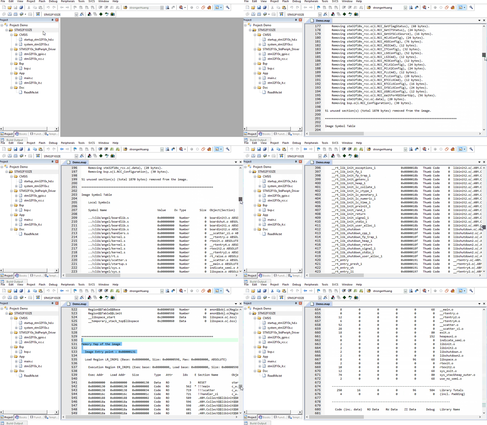
Of course, you can find the location of the map file (in the Listings folder) and open it with an editor tool.
2.2 Configuring map file output content
In the previous article “Keil Series Tutorial 05_Project Target Option Configuration (1)” in the Listings section, the map file was mentioned.
The configuration for map file output information is located at: Project -> Options for Target -> Listing, as shown below:
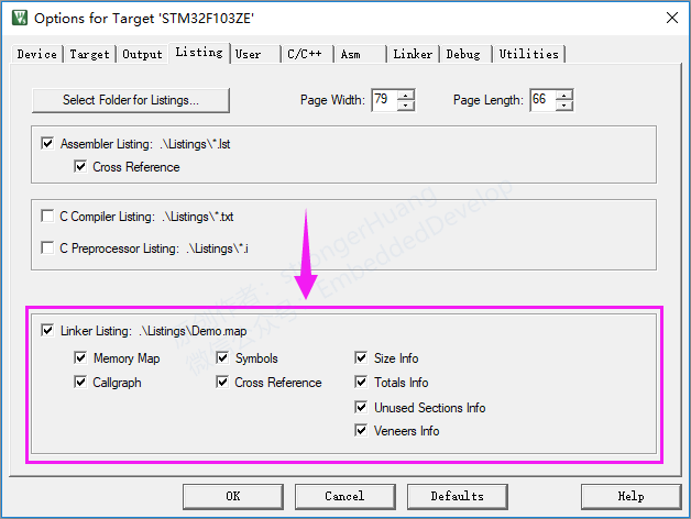
Main configurations include:
Memory Map: Memory Mapping
Callgraph: Call Graph
Symbols: Symbols
Cross Reference: Cross References
Size Info: Size Information
Totals Info: Total Information
Unused Section Info: Unused Module Information
Veneers Info: Veneer Information
We can select the corresponding information based on our needs for output.
Note:
A. By default, all information is output;
B. These configurations are combinatorial;
2.3 Classification of map file content
From the output configuration above, we can see the general categories of information contained in the map file. The map file is divided into the following five categories:
1.Section Cross References: Module and Segment (Entry) Cross References
2.Removing Unused input sections from the image: Removing Unused Modules
3.Image Symbol Table: Mapping Symbol Table
4.Memory Map of the image: Memory (Mapping) Distribution
5.Image component sizes: Storage Component Sizes
The following sections will elaborate on the five categories of content generated by the Keil DMK-ARM and ARM Compiler 5 components.
3
Section Cross References
Section Cross References: Module and Segment (Entry) Cross References
In the configuration, you need to check: Cross Reference
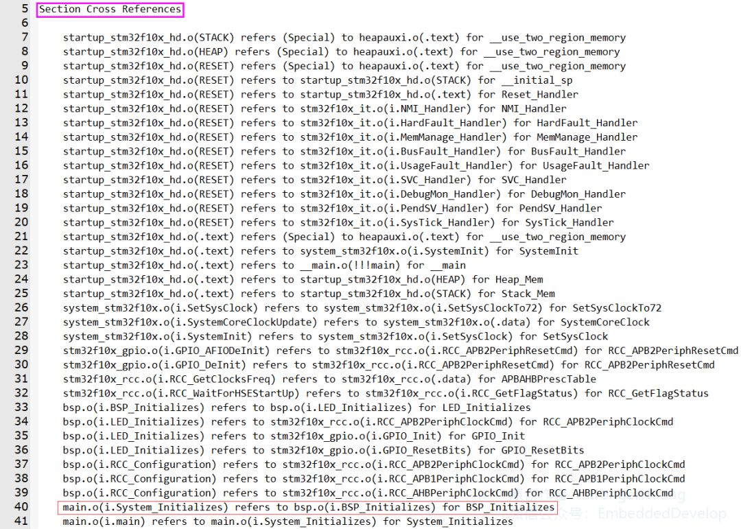
Section Cross References: Module and Segment (Entry) Cross References refer to the mutual references between the modules and segments (defined entries) generated by various source files.
For example:
main.o(i.System_Initializes) refers to bsp.o(i.BSP_Initializes) for BSP_Initializes
This means:
The System_Initializes function (i.System_Initializes) in the main module (main.o) references (or calls) the BSP_Initializes function in the bsp module (bsp.o).
Note:
A. main.o is the target file module generated from the main.c source file;
B. I.System_Initializes is the entry of the System_Initializes function.
4
Removing Unused input sections from the image
Removing Unused input sections from the image: Removing Unused Modules
In the configuration, you need to check: Unused Sections Info
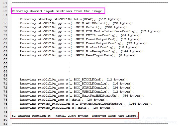
This category is easy to understand; it lists the modules (or functions) in our code that are not called in the map file.
For example:
Removing stm32f10x_gpio.o(i.GPIO_AFIODeInit), (20 bytes).
This means:
The GPIO_AFIODeInit module (function) in the stm32f10x_gpio.c file is not called, and its code size is 20 bytes.
Finally, there is a statistical information:
52 unused section(s) (total 2356 bytes) removed from the image.
1. A total of 52 sections were not called;
2. The size of the unused sections is 2356 bytes;
5
Image Symbol Table
Image Symbol Table: Mapping Symbol Table
In the configuration, you need to check: Symbols
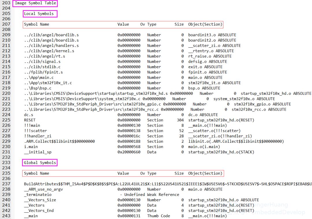
Image Symbol Table: is a table that stores the corresponding addresses of each segment (the image has removed the middle content).
5.1 Symbols are divided into two major categories:
1.Local Symbols: Local
2.Global Symbols: Global
5.2 Key points about Symbols:
1.Symbol Name: Symbol Name
The naming and classification of names can be found in the official reference document provided at the end.
2.Value: Corresponding address
You will find addresses like 0x0800xxxx, 0x2000xxxx.
0x0800xxxx refers to storage in FLASH for code, variables, etc.
0x2000xxxx refers to storage in RAM for variable Data, etc.
3.Ov Type: Type of the symbol
There are several types of symbols: Number, Section, Thumb Code, Data, etc.;
Careful readers will notice that global and static variables are located in the 0x2000xxxx memory RAM.
4.Size: Storage size
This is easy to understand; it refers to the size occupied by the current line Symbol.
5.Object(Section): Segment Target
This generally refers to the module (source file) it belongs to.
6
Memory Map of the image
Memory Map of the image: Memory (Mapping) Distribution
In the configuration, you need to check: Memory Map
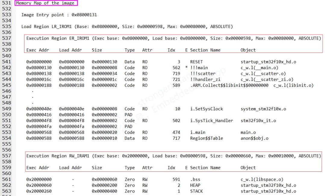
Memory Map of the image: is relatively detailed and an important item.
6.1 Main Introduction:
Image Entry point : 0x08000131: refers to the mapping entry address.
Load Region LR_IROM1 (Base: 0x08000000, Size: 0x00000598, Max: 0x00080000, ABSOLUTE):
Indicates that the loading region starts at LR_IROM1 address 0x08000000, with a size of 0x00000598, and a maximum of 0x00080000.
Execution Region:
A.Execution Region ER_IROM1
B.Execution Region RW_IRAM1
This region corresponds to the regions defined in our target configuration, as shown below:
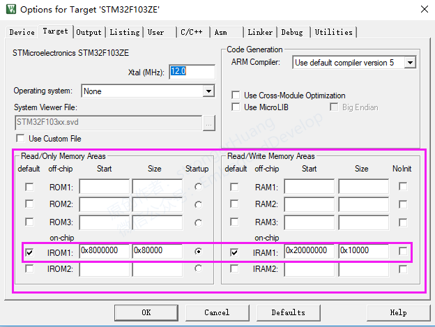
6.2 Key Points:
1.Base Addr: Storage Address
0x0800xxxx FLASH address and 0x2000xxxx RAM memory address.
2.Size: Storage Size
3.Type: Type
Data: Data Type
Code: Code Type
Zero: Uninitialized Variable Type
PAD: This type is placed in this position in the map file; it cannot be counted as a type here. If translated, it can only be described as a “padding type”.
The ARM processor is 32-bit, so if a variable of 8 or 16 bits is defined, there will be some remaining part, which refers to the “padding” portion. You will find that the other options do not have corresponding values.
4.Attr: Attributes
RO: Stored with the segment in ROM
RW: Stored with the segment in RAM
5.Section Name: Segment Name
This can also be referred to as the entry classification name, similar to the modules and segments mentioned in the first section “Section Cross References”.
It generally includes: RESET, .ARM, .text, i, .data, .bss, HEAP, STACK, etc.
6.Object: Target
7
Image component sizes
Image component sizes: Storage Component Sizes
In the configuration, you need to check: Size Info
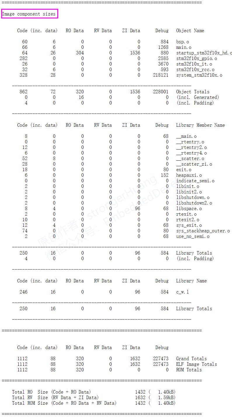
Image component sizes: Storage Component Sizes, mainly summarizes the storage size information of the modules.
This chapter’s content is something everyone can understand; after compiling the project, you generally see a segment of information in the compilation window, such as:
Program Size: Code=1112 RO-data=320 RW-data=0 ZI-data=1632
Code: refers to the size of the code;
Ro-data: refers to constant data excluding inline data;
RW-data: refers to readable and writable (RW), initialized variable data;
ZI-data: refers to uninitialized (ZI) variable data;
Reminder:
A.Code, Ro-data: are located in FLASH;
B.RW-data, ZI-data: are located in RAM;
C.RW-data initialized data will be stored in Flash and moved to RAM upon power-up.
The relationships are as follows:
RO Size = Code + RO Data
RW Size = RW Data + ZI Data
ROM Size = Code + RO Data + RW Data
You can refer to a previous article shared on my public account “Keil Compilation Size and Storage Description“
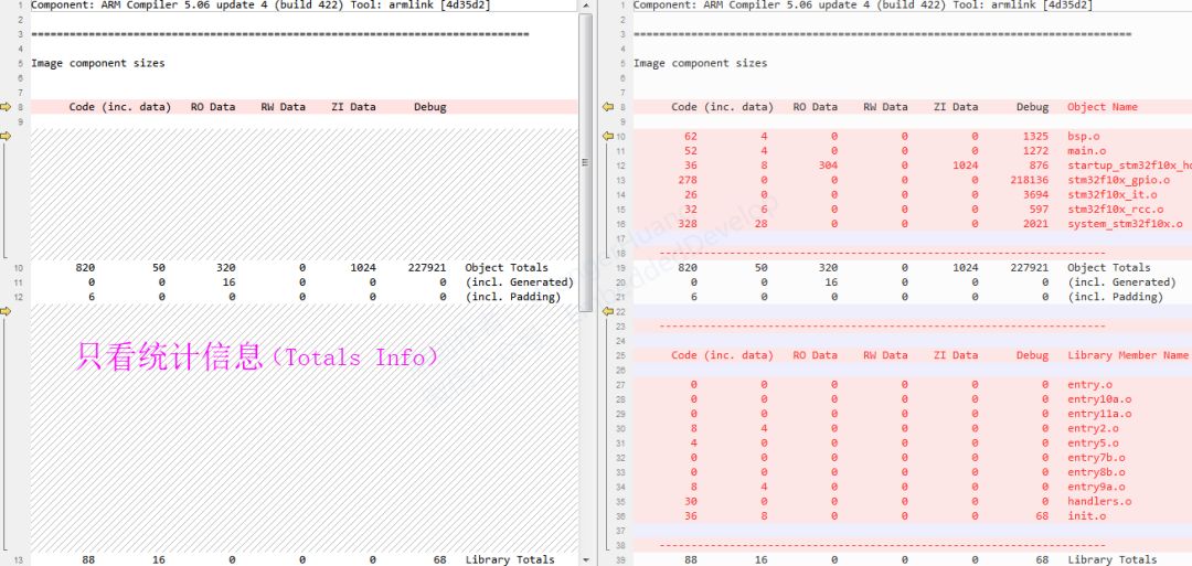
The above map information is a comprehensive summary; if you do not want to look at the details of those modules but only want to see the summary statistics, you can check only “Totals Info” in the configuration, for comparison:
Final Reminder:
Please refer to the PDF document that comes with Keil titled “ARM® Compiler v5.06 for µVision® armlink User Guide” for content.
8
Notes
1. This document is for personal learning use only, copyright reserved, commercial use prohibited.
2. This article is edited and organized by me alone, and there may be some errors.
3. This article is included in the public account “Embedded Column”; follow the public account and reply with 【Keil Series Tutorial】 to view the entire series of tutorials.
9Conclusion
If you find this article helpful, a thumbs up or share is a great support and encouragement for me.
Scan the QR code below, follow the public account, and check out more exciting content in the bottom menu!

Long press to recognize the QR code in the image to follow