Point “Jinan CNC Mould Technology Research Institute” focuses
Industry frontiers, mechanical videos, CNC processing technology, 3D printing, industrial robots, productionprocesses, molds, machine tools, and other cutting-edge information are waiting for you here!
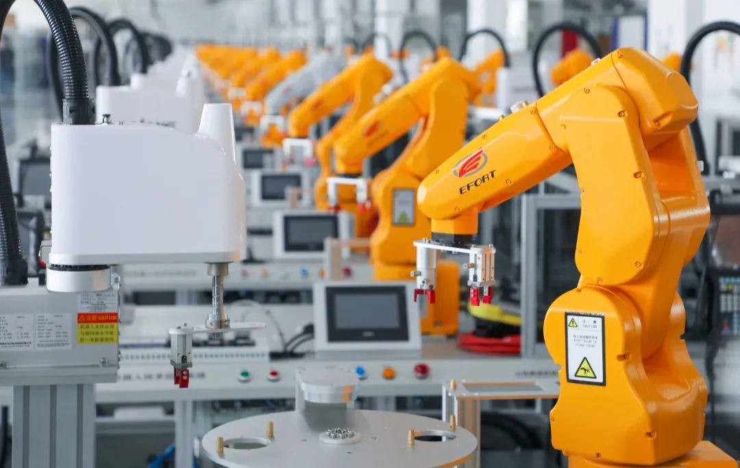
Industrial robots are crucial national instruments; the transition from “Made in China” to “Intelligent Manufacturing in China” will rely on industrial robots to upgrade manufacturing models; the large-scale deployment of industrial robots in China will be a strong indication of national strength…
This article provides a comprehensive introduction to the key technologies of industrial robots, making it worth sharing and reading!
In 1920, Czech playwright Karel Čapek first used the term ROBOT in his science fiction play “R.U.R. (Rossum’s Universal Robots)”, which subsequently became synonymous with robots.
In March 1938, The Meccano Magazine reported on a model of a handling robot, marking one of the earliest reports of a robot model aimed at industrial applications. It was designed by Griffith P. Taylor in 1935 and could achieve five-axis movement through a motor. By 1954, G.C. Devol from the USA designed the first electronic programmable industrial robot. In 1960, AMF in the USA produced the Versatran robot with a cylindrical coordinate system, capable of point and trajectory control, marking the first robot used in industrial production.
In 1974, Cincinnati Milacron successfully developed a multi-joint robot. By 1979, Unimation launched the PUMA robot, a multi-joint, fully electric-driven robot with multi-CPU secondary control, using VAL specialized language and could be equipped with visual, tactile, and force sensors, making it the most advanced industrial robot at that time. Today’s industrial robots are generally based on this structure. Robots from this period were “Teach-in/Playback” types, possessing only memory and storage capabilities, repeating tasks according to corresponding programs, with little awareness or feedback control capabilities regarding their surroundings.
Entering the 1980s, with the development of sensor technology, including visual sensors, non-visual sensors, and information processing technology, the second generation of robots—sensing robots—emerged. They could acquire some relevant information about the work environment and objects, perform real-time processing, and guide the robots in their tasks. The second generation of robots has been widely applied in industrial production.
The “intelligent robots” currently being researched by various countries not only have superior environmental perception capabilities compared to the second generation but also possess logical reasoning, judgment, and decision-making abilities, allowing them to work autonomously based on operational requirements and environmental information.
2. Application Scenarios of Industrial Robots
Since the creation of the first industrial robot in the early 1960s, robots have demonstrated remarkable vitality, with rapid advancements in robot technology over just 50 years. The most widely used field for industrial robots is the automotive and automotive parts manufacturing industry, and they are continually expanding into other fields such as machining, electronics, rubber and plastics, food, and wood and furniture manufacturing. In industrial production, welding robots, grinding and polishing robots, laser processing robots, painting robots, handling robots, and vacuum robots have been extensively adopted. Below are some introductions to the application scenarios and technical characteristics of industrial robots.
3. Current State of Industrial Robots
With the rise of industrial robots, “machine replacement of labor” is becoming a trend. Foxconn previously announced plans to purchase one million robots within three years, expecting to establish the “world’s largest intelligent robot production base” in Jincheng, Shanxi by 2016.
The automotive, electronics, food, chemical, rubber, and metal products industries are considered the primary fields for the current application of industrial robots. Institutions predict that there will be an annual demand of 1 to 2 million units, accounting for about 70% of China’s industrial robot market demand.
As of September this year, there are nearly 420 robot companies throughout China. Additionally, over 30 robot industrial parks are currently under construction across various regions in China.
The rapid rise of industrial robots in the Chinese market is primarily due to cost; robots typically cost only one-fourth of labor costs. Furthermore, robots can provide significant added value in terms of quality, efficiency, and management. Thus, with the rapid advancement of robot technology, significant price reductions, labor shortages, and rising labor costs, China’s industrial robot industry is currently experiencing an explosive growth phase.
4. Key Technologies of Industrial Robots
1. Basic System Components of Robots
Industrial robots consist of three main parts and six subsystems. The three main parts are the mechanical part, sensing part, and control part. The six subsystems can be divided into mechanical structure system, drive system, perception system, robot environment interaction system, human-machine interaction system, and control system.
1) The mechanical structure system of industrial robots is composed of the base, arm, and end effector, each of which has several degrees of freedom. If the base has a walking mechanism, it forms a mobile robot; if it lacks walking and bending mechanisms, it forms a single robotic arm. The arm generally consists of an upper arm, lower arm, and wrist. The end effector is an important component directly mounted on the wrist and can be a two-finger or multi-finger gripper, or tools such as a spray gun or welding tool.
2) The drive system is necessary for the robot to operate, requiring drive devices to be installed at each joint or each degree of freedom. The drive system can be hydraulic, pneumatic, electric, or a combination of these basic types. It can be direct drive or indirect drive through synchronous belts, chains, gears, or harmonic gear mechanisms.
3) The perception system consists of internal sensor modules and external sensor modules to obtain meaningful information about internal and external environmental states. The use of intelligent sensors enhances the robot’s mobility, adaptability, and intelligence levels. The human sensory system is extremely adept at perceiving external world information; however, for certain specific information, sensors can be more effective than the human sensory system.
4) The robot environment interaction system is a system that establishes connections and coordination between modern industrial robots and external devices in the environment. Industrial robots and external devices can be integrated into a functional unit, such as processing units, welding units, assembly units, etc. It can also consist of multiple robots, machine tools or equipment, and several parts storage devices to execute complex tasks.
5) The human-machine interaction system is the device through which operators control and communicate with the robot, such as standard terminals, command consoles, information display boards, and danger signal alarms. This system can be classified into two main categories: command input devices and information display devices.
6) The robot control system is the brain of the robot, which is the main factor determining the robot’s functionality and performance.
The task of the control system is to manage the robot’s execution mechanisms according to the robot’s operational instruction program and the feedback signals from sensors to complete specified movements and functions. If the industrial robot lacks information feedback features, it is an open-loop control system; if it possesses information feedback features, it is a closed-loop control system. Based on control principles, control systems can be classified into program control systems, adaptive control systems, and artificial intelligence control systems. Based on the form of control operation, control systems can be divided into point control and trajectory control. Point control only manages the accurate positioning of the execution mechanism from one point to another, suitable for loading and unloading, spot welding, and general handling tasks; continuous trajectory control can manage the execution mechanism’s movement along a specified trajectory, suitable for continuous welding and painting tasks.
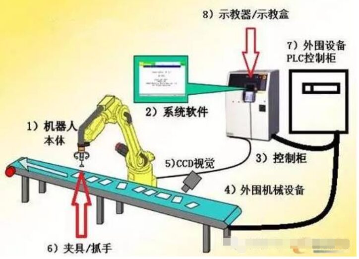
The task of the control system is to manage the robot’s execution mechanisms according to the robot’s operational instruction program and the feedback signals from sensors to complete specified movements and functions. If the industrial robot lacks information feedback features, it is an open-loop control system; if it possesses information feedback features, it is a closed-loop control system. Based on control principles, control systems can be classified into program control systems, adaptive control systems, and artificial intelligence control systems. Based on the form of control operation, control systems can be divided into point control and trajectory control. A complete industrial robot includes the robot body, system software, control cabinet, peripheral mechanical devices, CCD vision, fixtures/grippers, and peripheral devices such as PLC control cabinets, and teaching devices/teaching boxes.
Next, we will focus on the drive system and perception system of robots.
2. Drive System of Robots
The drive system of industrial robots can be categorized into three main types based on the power source: hydraulic, pneumatic, and electric. Depending on requirements, these three basic types can also be combined to form composite drive systems. Each of these three basic drive systems has its own characteristics.
Hydraulic drive systems are favored due to their mature technology. They have high power, a large power-to-inertia ratio, rapid response, and ease of achieving direct drive. They are suitable for robots that work in environments with high load capacities and inertia. However, hydraulic systems require energy conversion (from electrical energy to hydraulic energy), and speed control is often achieved through throttling, resulting in lower efficiency compared to electric drive systems. Additionally, hydraulic fluid leaks can cause environmental pollution, and the noise level is relatively high. Due to these drawbacks, electric systems are often replacing hydraulic systems in robots with loads under 100 kg.
Qingdao East China Engineering Machinery Co., Ltd. has developed a fully hydraulic heavy-duty robot, as shown in the figure. Its large span can reach 2000 kg, and the robot’s working radius can reach nearly 6 m, applied in the casting and forging industry.
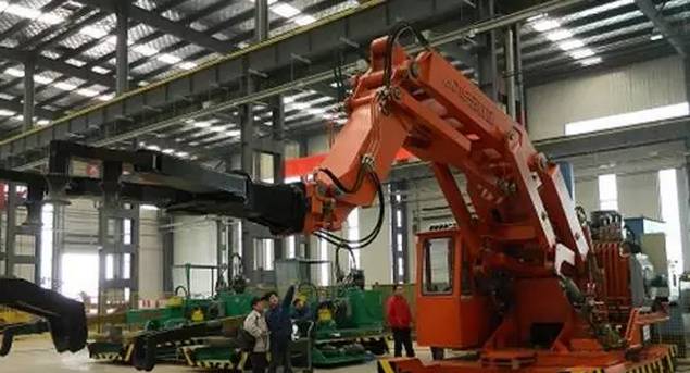 Fully hydraulic heavy-duty robot
Pneumatic drives have advantages such as fast speed, simple system structure, convenient maintenance, and low cost. However, due to the low working pressure of pneumatic devices, precise positioning is difficult, and they are generally only used to drive the end effectors of industrial robots. Pneumatic grippers, rotating cylinders, and pneumatic suction cups can be used as end effectors for handling and assembly of medium and small loads. Pneumatic suction cups and pneumatic robot grippers are shown in the figure.
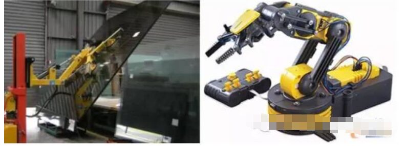
Pneumatic suction cups and pneumatic robot grippers
Electric drive is a mainstream driving method for modern industrial robots, divided into four main types: DC servo motors, AC servo motors, stepper motors, and linear motors. DC and AC servo motors use closed-loop control and are generally used for high-precision, high-speed robot drives; stepper motors are used in situations where precision and speed requirements are not high and use open-loop control; linear motors and their drive control systems have become increasingly mature, offering performance advantages that traditional drive devices cannot match, such as adaptability to very high and very low-speed applications, high acceleration, high precision, minimal backlash, low wear, simple structure, and no need for reducers or gear screw couplings. Given the significant demand for linear drives in parallel robots, linear motors are widely used in the field of parallel robots.
3. Perception System of Robots
The robot perception system transforms various internal state information and environmental information into data and information that the robot itself or robots can understand and utilize. In addition to sensing mechanical quantities related to its working state, such as displacement, speed, acceleration, force, and torque, visual perception technology is a significant aspect of industrial robot perception.
The visual servo system uses visual information as feedback signals to control and adjust the robot’s position and posture. This application is mainly reflected in the semiconductor and electronics industries. Machine vision systems are also widely used in quality inspection, workpiece identification, food sorting, and packaging.
Typically, robot visual servo control is based on position-based visual servo or image-based visual servo, which are also known as three-dimensional and two-dimensional visual servos, respectively. Each of these methods has its advantages and applicability, but they also have some limitations, leading to the proposal of the 2.5-dimensional visual servo method.
The position-based visual servo system utilizes camera parameters to establish a mapping relationship between image information and the position/posture information of the robot’s end effector, achieving closed-loop control of the end effector’s position. The position and posture error of the end effector is estimated based on the position information extracted from real-time captured images and the geometric model of the target location, and new pose parameters for each joint are obtained based on position and posture errors. Position-based visual servo requires that the end effector can always be observed within the visual scene to calculate its three-dimensional position and posture information. Eliminating interference and noise in images is crucial for ensuring the accuracy of position and posture error calculations.
Two-dimensional visual servo compares the image captured by the camera with a given image (not three-dimensional geometric information) to obtain an error signal. Then, corrections are made through the joint controller and visual controller in conjunction with the robot’s current operating state to achieve servo control. Compared to three-dimensional visual servo, two-dimensional visual servo exhibits stronger robustness against calibration errors of the camera and robot, but issues such as the singularity of the image Jacobian matrix and local minima are inevitably encountered during the design of visual servo controllers.
To address the limitations of three-dimensional and two-dimensional visual servo methods, F. Chaumette and others proposed the 2.5-dimensional visual servo method. This method decouples the closed-loop control of the camera’s translational and rotational movements, reconstructing the orientation and imaging depth ratio of objects in three-dimensional space based on image feature points, with the translational part represented by the feature point coordinates in the image plane. This method successfully integrates image signals with pose signals extracted from images, and combines the error signals they generate for feedback, significantly addressing issues such as robustness, singularity, and local minima. However, some problems still need resolution, such as ensuring that the reference object remains within the camera’s field of view during the servo process and the non-uniqueness of solutions when decomposing the homography matrix.
When establishing the visual controller model, it is necessary to find a suitable model to describe the mapping relationship between the robot’s end effector and the camera. The image Jacobian matrix method is widely used in the field of robot visual servo research. The image Jacobian matrix is time-varying, so it needs to be computed or estimated online.
4. Key Basic Components of Robots
Robots consist of four major components, with the body cost accounting for 22%, servo system 24%, reducer 36%, and controller 12%. The key basic components of robots refer to the parts that constitute the robot’s drive system, control system, and human-machine interaction system, which have a critical impact on the robot’s performance and possess generality and modularity. The key basic components of robots are mainly divided into the following three parts: high-precision robot reducers, high-performance AC/DC servo motors and drivers, and high-performance robot controllers.
1) Reducers
Reducers are critical components of robots, and currently, two main types of reducers are used: harmonic gear reducers and RV reducers.
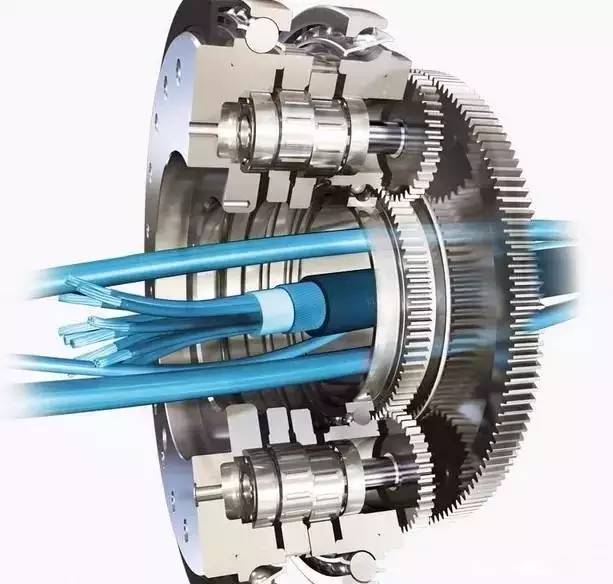 The harmonic drive method was invented by American inventor C. Walt Musser in the mid-1950s. The harmonic gear reducer mainly consists of three basic components: a wave generator, flexible gear, and rigid gear, relying on the wave generator to induce controllable elastic deformation in the flexible gear, which then meshes with the rigid gear to transmit motion and power. The single-stage transmission ratio can reach 70-1000, and thanks to the deformation of the flexible gear, backlash-free meshing can be achieved. Compared to general reducers, when the output torque is the same, the volume of harmonic gear reducers can be reduced by two-thirds, and the weight can be halved. The flexible gear bears significant alternating loads, so its material fatigue strength, processing, and heat treatment requirements are high, and the manufacturing process is complex; the performance of the flexible gear is crucial for high-quality harmonic gear reducers.
German inventor Lorenz Baraen proposed the principle of cycloidal pinwheel planetary gear transmission in 1926, and the RV reducer was first developed by Teijin Seiki Co., Ltd. in Japan in the 1980s. The RV reducer consists of a pre-stage planetary gear reducer and a post-stage cycloidal pinwheel reducer. Compared to harmonic gear reducers, RV reducers offer better rotational precision and precision retention.
Chen Shixian invented the active tooth transmission technology. The fourth generation of active tooth transmission—the all-rolling active tooth transmission (oscillatory roller transmission, ORT)—has been successfully applied to various industrial products. The compound oscillatory roller transmission (CORT) proposed based on ORT not only has advantages similar to RV transmission but also overcomes the disadvantages of RV transmission, such as high bearing forces and low lifespan, further enhancing the service life and load capacity; the structure of CORT allows for smaller backlash under the same precision indicators, higher motion precision and stiffness, alleviating the requirement for high manufacturing precision in RV transmission, thus relatively reducing processing requirements and manufacturing costs. CORT is independently developed in China and has independent intellectual property rights. Anshan Wear-resistant Alloy Research Institute and Zhejiang Hengfengtai Reducer Manufacturing Co., Ltd. have successfully developed CORT reducers for robots.
ORT reducer CORT reducer
Currently, in the high-precision robot reducer market, 75% of the market share is monopolized by two Japanese reducer companies, namely Nabtesco, which provides RV cycloidal pinwheel reducers, and Harmonic Drive, which provides high-performance harmonic reducers. The reducers for international mainstream robot manufacturers, including ABB, FANUC, KUKA, and MOTOMAN, are primarily supplied by these two companies. Unlike the general models chosen by domestic robot companies, international mainstream robot manufacturers have signed strategic cooperation agreements with the above two companies, with most of the products being specialized models improved based on general models according to the specific requirements of each manufacturer. Domestic research on high-precision cycloidal pinwheel reducers started relatively late, with some universities and research institutes having conducted related research. Currently, there are no mature products applied in industrial robots. In recent years, some domestic manufacturers and universities have begun to focus on the localization and industrialization of high-precision cycloidal pinwheel reducers, such as Zhejiang Hengfengtai, Chongqing University’s National Key Laboratory of Mechanical Transmission, Tianjin Reducer Factory, Qinchuan Machine Tool Factory, and Dalian Railway Institute. In the field of harmonic reducers, there are already alternative products available, such as those from Beijing Zhongji Kemei and Beijing Harmonic Drive Institute, but these products still have significant gaps compared to Japanese products in terms of input speed, torsion height, transmission accuracy, and efficiency, and their mature application in industrial robots has only just begun.
The performance comparison of mainstream high-precision harmonic reducers in domestic and international industrial robots is as follows.
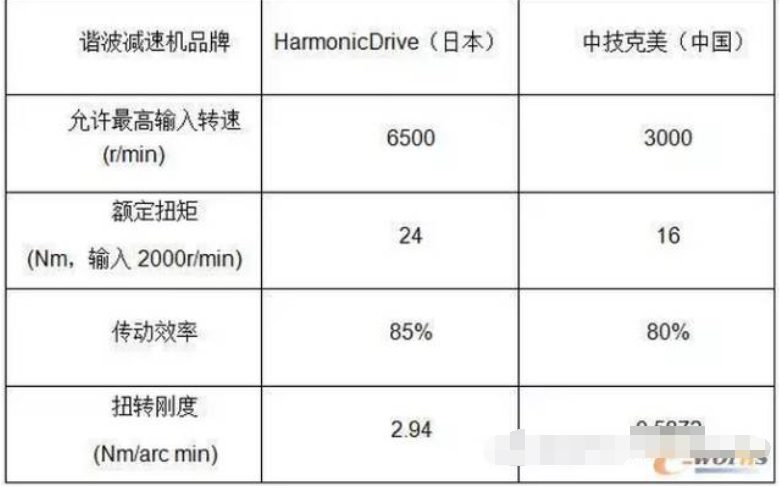
Table 1 Performance Comparison of Mainstream High-Precision Harmonic Reducers
Note: The comparative data in the table is from similar models:
HD: CSF-17-100
Zhongji Kemei: XB1-40-100
Transmission efficiency test conditions: input speed 1000r/min, temperature 40°
Torsional stiffness test conditions: within 20% rated torque
The performance comparison of mainstream high-precision cycloidal pinwheel reducers in domestic and international industrial robots is as follows.
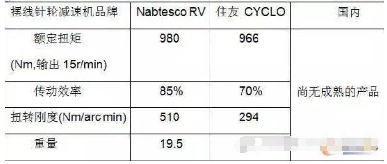
Table 2 Performance Comparison of Mainstream High-Precision RV Cycloidal Pinwheel Reducers
Note: The comparative data in the table is from similar models:
RV: 100C
CYCLO: F2CF-C35
Transmission efficiency test conditions: output speed 15r/min, rated torque
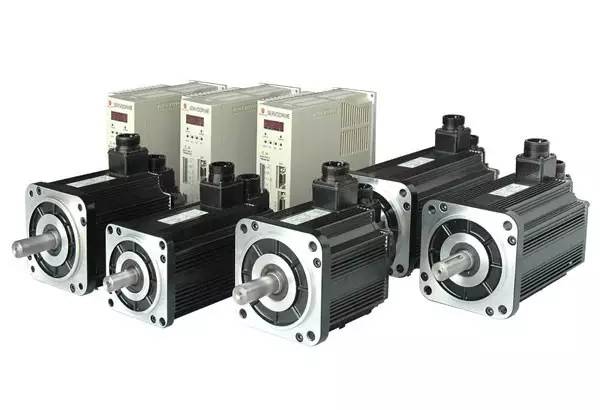
2) Servo Motors
In terms of servo motors and drives, the driving parts of European robots are mainly provided by companies such as Lenze, Lust, and Bosch Rexroth, which offer overload capacity, good dynamic response, strong openness, and bus interfaces, but at a high cost. The key components of Japanese brand industrial robots are mainly provided by companies such as Yaskawa, Panasonic, and Mitsubishi, which are relatively cheaper but have poorer dynamic response and openness, with most only providing analog and pulse control methods. In recent years, domestic companies have also begun foundational research and industrialization of high-power AC permanent magnet synchronous motors and drives, such as Harbin Institute of Technology, Beijing Heli, and Guangzhou CNC, and have achieved some production capacity, but their dynamic performance, openness, and reliability still require more practical robot project applications for validation.
 3) Controllers
In terms of robot controllers, the controllers of mainstream international robot manufacturers are generally developed independently based on universal multi-axis motion controller platforms. The common multi-axis controller platforms mainly consist of motion control cards based on embedded processors (DSP, POWER PC) and PLC systems based on industrial computers with real-time systems, represented by Delta Tau’s PMAC card and Beckhoff’s TwinCAT system. In terms of motion control cards, the domestic company GSK has developed corresponding mature products, but their application in robots is still relatively limited.
5. Robot Operating Systems
The general robot operating system (robot operating system, ROS) is a standardized construction platform designed for robots, allowing every robot designer to use the same operating system for robot software development. ROS will promote the robotics industry towards hardware and software independence. The independent development model of hardware and software has greatly facilitated the development and rapid progress of PC, laptops, and smartphones.
The development difficulty of ROS is greater than that of computer operating systems, as computers only need to handle clearly defined mathematical operation tasks, while robots face more complex real-world motion operations.
ROS provides standard operating system services, including hardware abstraction, low-level device control, common function implementation, inter-process messaging, and data packet management.
ROS is divided into two layers: the lower layer is the operating system layer, and the upper layer consists of various software packages contributed by the user community to implement different functions of robots.
The existing robot operating system architecture is mainly based on the Linux-based Ubuntu open-source operating system. Additionally, institutions such as Stanford University, MIT, and Munich University in Germany have developed various ROS systems. The Microsoft robotics development team also launched a “Windows Robot Version” in 2007.
6. Robot Motion Planning
To improve work efficiency and enable robots to complete specific tasks in the shortest time possible, reasonable motion planning is necessary. Offline motion planning is divided into path planning and trajectory planning.
The goal of path planning is to maximize the distance from obstacles while minimizing the length of the path; the main objective of trajectory planning is to minimize the robot’s running time or energy consumption during joint space movement. Trajectory planning adds time series information to path planning to plan the speed and acceleration of the robot during task execution, meeting the requirements for smoothness and controllability of speed.
Teach-in playback is one method to achieve path planning, where teaching is conducted through the operating space and the teaching results are recorded, which can then be reproduced during work. On-site teaching directly corresponds to the actions the robot needs to perform, making the path intuitive and clear. The downside is that it requires experienced operators and consumes a lot of time, and the path may not be optimized. To solve these problems, a virtual model of the robot can be established, allowing for visual operations to complete path planning for tasks.
Path planning can be performed in joint space. Gasparetto uses quintic B-splines as the interpolation function for joint trajectories and optimizes the integral of the square of acceleration with respect to motion time as the objective function to ensure smooth movement of each joint. Liu Songguo applies quintic B-splines for joint trajectory interpolation calculations, allowing for arbitrary configuration of the endpoint values of each joint’s speed and acceleration based on smoothness requirements. Additionally, trajectory planning in joint space can avoid singularity issues in the operating space. Huo and others designed a joint trajectory optimization algorithm that avoids singularity in joint space, utilizing the redundancy of a six-degree-of-freedom arc welding robot during task execution, treating the robot’s singularity and joint constraints as constraints, and optimizing calculations using the TWA method.
Comparing joint space path planning with operating space path planning has the following advantages:
① It avoids singularity issues in the operating space of the robot;
② Since the robot’s movement is controlled by the motion of joint motors, in joint space, it avoids a large number of forward and inverse kinematics calculations;
③ The trajectories of each joint in joint space are more amenable to control optimization.
5. Classification of Industrial Robots
Industrial robots can be classified into the following types based on different methods:
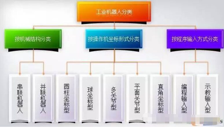
Classification of Industrial Robots
1. From the perspective of mechanical structure, they can be divided into serial robots and parallel robots.
1) The characteristic of serial robots is that the movement of one axis will change the origin of another axis, making the forward solution of serial robots easy, but the inverse solution very difficult;
2) Parallel robots use parallel mechanisms, where the movement of one axis does not change the origin of another axis. Parallel robots have advantages such as high rigidity, stable structure, high load capacity, high precision in micro-movements, and low motion load. Their forward solution is difficult, but the inverse solution is very easy. Serial and parallel robots are illustrated in the figure.
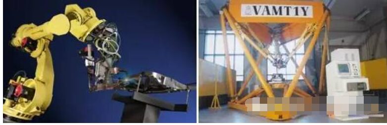
Serial robots, parallel robots
2. Industrial robots can be categorized based on the coordinate forms of the operating machines:(The coordinate form refers to the reference coordinate system taken by the operating machine’s arm during movement.)
1) Rectangular coordinate industrial robots
Their movement consists of three mutually perpendicular linear movements (i.e., PPP), and their working space forms a rectangular shape. The moving distances along each axis can be directly read on each coordinate axis, making programming calculations for position and posture intuitive, with high positioning accuracy, uncoupled control, and simple structure. However, their body occupies a large space, has a small action range, and poor flexibility, making coordination with other industrial robots difficult.
2) Cylindrical coordinate industrial robots
Their movement is achieved through a combination of one rotation and two linear movements, forming a cylindrical working space. Compared to rectangular coordinate industrial robots, they occupy a smaller body volume with a larger movement range under the same working space conditions, and their positioning accuracy is second only to rectangular coordinate robots, but they also face challenges in coordinating with other industrial robots.
3) Spherical coordinate industrial robots
Spherical coordinate industrial robots, also known as polar coordinate industrial robots, consist of two rotations and one linear movement (i.e., RRP, one rotation, one pitch, and one stretching movement), forming a spherical working space. They can perform pitch actions and grasp coordinated workpieces on the ground or at low positions, with high positioning accuracy, and the positioning error is proportional to arm length.
4) Multi-joint industrial robots
Also known as revolute coordinate industrial robots, these industrial robots have arms similar to human upper limbs. Their first three joints are revolute pairs (i.e., RRR). This type of industrial robot generally consists of a column and upper and lower arms, with the column forming a shoulder joint with the upper arm and the upper and lower arms forming an elbow joint, allowing the upper arm to perform rotational movements and pitching, and the lower arm to pitch. This structure is the most compact, offers great flexibility, occupies the smallest area, and can coordinate with other industrial robots, but has lower positioning accuracy and balance issues, leading to control coupling; this type of industrial robot is increasingly widely applied.
5) Planar joint industrial robots
They use one moving joint and two revolute joints (i.e., PRR), with the moving joint achieving vertical movement, while the two revolute joints control front-back and left-right movements. This form of industrial robot is also known as a SCARA (Selective Compliance Assembly Robot Arm) robot. It exhibits compliance in the horizontal direction and significant rigidity in the vertical direction. Its simple structure and flexible movements make it widely used in assembly tasks, especially suitable for the insertion and assembly of small parts, such as in the electronics industry.
3. Industrial robots can be distinguished by the method of program input: programming input type and teaching input type:
1) Programming input type involves transferring pre-written operational program files from a computer to the robot control cabinet via communication methods such as RS232 serial ports or Ethernet.
2) Teaching input types have two methods: teaching box teaching and operator-led teaching of the execution mechanism.
Teaching box teaching involves the operator using a manual controller (teaching box) to send instruction signals to the drive system, causing the execution mechanism to perform the required action sequence and motion trajectory. Industrial robots that use teaching boxes for teaching are quite common, and most industrial robots are equipped with teaching box functionality. However, for complex working trajectories, teaching box teaching may not achieve ideal results, such as in painting robots used for complex curved surfaces.
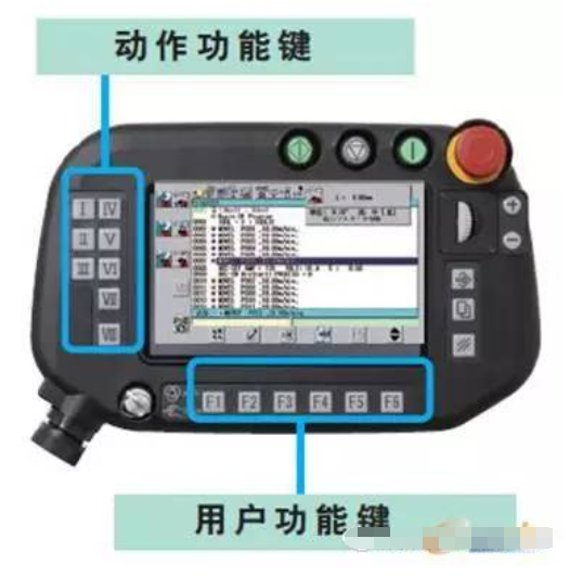
Robot teaching box
In operator-led teaching, the operator directly manipulates the execution mechanism to perform the required action sequence and motion trajectory. During the teaching process, the information of the working program is automatically stored in the program memory, and when the robot operates automatically, the control system retrieves the corresponding information from the program memory, sending instruction signals to the drive mechanism to reproduce the various actions taught.
6. Performance Evaluation Indicators of Industrial Robots
The basic parameters and performance indicators representing robot characteristics mainly include working space, degrees of freedom, effective load, motion accuracy, motion characteristics, and dynamic characteristics.
1. Performance evaluation indicators of industrial robots
Working space (Work space) refers to the set of positions in space that a specific part of the robot arm can reach under certain conditions. The characteristics and size of the working space reflect the robot’s working capability. When understanding the robot’s working space, the following points should be noted:
1) The working space indicated in the industrial robot’s manual typically refers to the range that the mechanical interface coordinate system at the wrist can reach in space, i.e., the range that the center point of the wrist flange can reach in space, rather than the range that the end effector’s endpoint can reach. Therefore, when designing and selecting, it is essential to pay attention to the actual working space that the robot can reach after installing the end effector.
2) The working space provided in the robot’s manual is often smaller than the maximum space in terms of kinematics. This is because in the reachable space, the effective load, maximum allowable speed, and maximum acceleration vary with different arm postures, and the maximum position allowed at the arm’s maximum position is usually smaller than at other positions. Moreover, there may be issues of degree of freedom degeneration at the boundary of the robot’s maximum reachable space, and such postures are called singular postures, which can lead to a significant range of degree of freedom degeneration around singular postures, rendering that portion of the working space unusable during robot operation.
3) Besides the edges of the working space, industrial robots may also have areas within the working space that the arm cannot reach due to mechanical structural limitations, known as cavities or voids. A cavity refers to a completely closed space within the working space that the end effector cannot reach, while a void refers to a space that the end effector cannot reach along the entire length around the axis of rotation.
2. Degrees of freedom refer to the number of variables required for the operating machine to move in space, representing a parameter that indicates the robot’s flexibility of action, typically expressed as the number of independent movements along axes and rotations around axes.
A free object in space has six degrees of freedom (three rotational degrees and three translational degrees). Industrial robots are often open kinematic chains, with each joint movement pair having only one degree of freedom, so the number of degrees of freedom of the robot typically equals the number of its joints. The more degrees of freedom a robot has, the stronger its functionality. Currently, industrial robots typically have 4-6 degrees of freedom. When the number of joints (degrees of freedom) increases to the point where it no longer affects the orientation and positioning of the end effector, redundancy occurs. The appearance of redundancy increases the flexibility of robot operation but also complicates control.
In terms of motion modes, industrial robots can generally be divided into linear motion (abbreviated as P) and rotational motion (abbreviated as R). The application of these abbreviations can indicate the characteristics of the operating machine’s motion degrees of freedom, such as RPRR indicating that the robot operating machine has four degrees of freedom, with the joint movement modes being rotation-linear-rotation-rotation from the base to the end effector. Additionally, the motion degrees of freedom of industrial robots are also limited by their motion range.
3. Effective Load (Payload)
Effective load refers to the weight of the object that the robot operating machine can carry or the force or torque it can withstand during operation, indicating the load capacity of the operating machine.
Since the maximum allowable weight that a robot can carry varies with different postures, the rated payload of the robot refers to the maximum weight the arm can carry at any posture within its working space.
4. Motion Accuracy (Accuracy)
The accuracy of the robot’s mechanical system mainly involves posture accuracy, repeat posture accuracy, trajectory accuracy, and repeat trajectory accuracy.
Posture accuracy refers to the deviation between the instructed posture and the actual posture when approaching the instructed posture from the same direction. Repeat posture accuracy refers to the inconsistency of the actual posture after responding n times to the same instructed posture from the same direction.
Trajectory accuracy refers to the degree to which the robot’s mechanical interface approaches the instructed trajectory from the same direction n times. Repeat trajectory accuracy refers to the inconsistency between the actual trajectories after following a given trajectory in the same direction n times.
5. Motion Characteristics (Speed)
Speed and acceleration are the primary indicators of the robot’s motion characteristics. In the robot’s manual, the maximum stable speed of the main motion degrees of freedom is usually provided, but in practical applications, simply considering the maximum stable speed is insufficient; attention must also be given to the maximum allowable acceleration.
6. Dynamic Characteristics Structural Dynamic Parameters
Mainly include mass, moment of inertia, stiffness, damping coefficient, natural frequency, and vibration modes.
During design, efforts should be made to minimize mass and inertia. If stiffness is poor, the robot’s posture accuracy and system’s natural frequency will decrease, leading to dynamic instability; however, for certain tasks (such as assembly operations), appropriately increasing compliance can be beneficial. Ideally, it is desirable for the robot’s arm stiffness to be adjustable. Increasing system damping can help shorten the oscillation decay time and improve the system’s dynamic stability. Enhancing the system’s natural frequency to avoid working frequency ranges can also help improve system stability.
7. Technical Challenges Faced by Industrial Robots
1. Ninety percent of the robot market is foreign capital.
The robot market is thriving, but the Chinese robot industry faces challenges. According to market statistics, the industrial robot market in mainland China is dominated by foreign manufacturers, with Japanese brands accounting for 52%, European manufacturers for 30%, and the remaining approximately 10% for mainland Chinese manufacturers.
Due to the high entry barriers in the robot industry, the top four global robot manufacturers are Japan’s FANUC, Yaskawa, ABB, and KUKA, collectively accounting for 50% of the market share.
On the other hand, the industrial robot market in mainland China is expected to maintain a high growth rate of at least 30% for the next 30 years. Consequently, global brand robot manufacturers are actively expanding their robot business sales scale in mainland China, including FANUC, Yaskawa, ABB, and KUKA, all of which are actively establishing positions and factories in mainland China.
Currently, while the industrial robots in mainland China have made some progress in industrialization, they still lag behind foreign counterparts in terms of precision, speed, and other aspects, resulting in low levels of industrial application and market share; some products only reach the technological level of foreign products from the mid-1990s.
According to Li Xiaojia, director of the data statistics center of the China Robot Industry Alliance, in 2013, China purchased and assembled nearly 37,000 industrial robots, with foreign robots predominantly featuring six axes or more high-end industrial robots, almost monopolizing high-end sectors such as automotive manufacturing and welding, accounting for 96%. In contrast, domestic robots are mainly used for handling and loading/unloading tasks, placing them in lower-end sectors.
It is noteworthy that the current development of the robot industry in China risks further widening the gap with foreign counterparts. Overall, the Chinese robot industry is still in its infancy, lacking brand recognition, with the largest robot enterprises producing only a few thousand robots annually. As foreign robot companies increasingly view China as a production base, the development space for domestic brand industrial robot companies will be further compressed.
Simultaneously, due to reliance on key core components, the risk of industrial hollowing out is expanding. The three key components of industrial robots (motors and servos, reducers, control systems) primarily come from abroad, and mainland Chinese manufacturers generally lack competitive research and manufacturing capabilities, leading to long-term dependence on imports. Without core component manufacturers supporting the upstream of the industrial chain, they will remain dependent on foreign sources.
2. Technical challenges faced by industrial robots
We must recognize the significant challenges faced by the development of China’s industrial robot industry.
Firstly, the top-level architecture design and foundational technologies of robots are controlled by developed countries. The components that account for a significant proportion of the cost structure of robots, such as reducers, servo motors, controllers, and CNC systems, are heavily reliant on imports, meaning that domestic robots do not have a significant cost advantage.
Secondly, there is a risk of being locked into low-end products. On one hand, developed countries are unlikely to easily transfer or authorize core robot technologies and patents to China, presenting many obstacles for Chinese robot companies to enter mid-to-high-end markets through participation in international standard-setting and technological cooperation. On the other hand, local governments’ blind investments in industries may lead to overcapacity, resulting in redundant constructions and price competition.
Furthermore, there is a lack of effective connection between robot research and development, manufacturing, and application. Universities and research institutes that are leading in relevant robot technology research do not possess market development capabilities, while enterprises invest very little in foundational research. The integration of production, education, and research in China faces many systemic and institutional barriers, leading to a disconnect between research and manufacturing.
In response to the current situation of foreign monopolies in the domestic market, experts suggest seeking breakthroughs and surpassing through various means: firstly, strengthening tracking research on international robot technology and formulating a “robot technology roadmap” that aligns with China’s development realities, clarifying the steps for technological development, key core technologies, processes, components, and industrialization paths to be prioritized.
Secondly, establishing a robot development model that suits China’s development realities. Strengthening integration applications in segmented industry fields, enhancing collective efforts in production, education, and research, and focusing on breakthroughs in key core components to quickly form a complete industrial chain encompassing robot bodies, key components, and system integrators.
Additionally, accelerating the cultivation of leading enterprises and brands in industrial robots. China should regard the cultivation and development of independent brand industrial robots as an important task for upgrading the Chinese economy. An industrial robot industry directory should be established, and efforts should be coordinated to promote the localization of industrial robots.