Composition and Working Principle of Electric Power Steering System (EPS)

Typically, EPS consists of a torque sensor that detects the steering torque of the driver, an EPS ECU that calculates the assist torque based on the torque signal and controls the motor drive, a motor that generates assist, and a reducer that transmits the motor drive force to the steering mechanism.

Composition and Working Principle of Electric Power Steering System (EPS)

EPS Composition ▲

1

Types of EPS

As shown in the figure below, EPS can be divided into three types based on the type of motor and the position of assistance: Column Assist, Gear Assist, and Rack Assist.

Composition and Working Principle of Electric Power Steering System (EPS)

Column assist EPS is cost-effective and widely adopted.Gear assist EPS has a motor arranged near the gear.Rack assist EPS has its final output end close to the tire’s rack, thus minimizing assist loss;Moreover, the actuator is far from the driver, resulting in less noise and vibration, making it mostly used in high-end vehicles.Both the actuator and controller of rack assist EPS are arranged in the engine compartment, requiring heat resistance and waterproof performance, which increases the system’s cost.

2

EPS Motor

The motors that can be used in EPS are divided into brushed motors and brushless motors.

Composition and Working Principle of Electric Power Steering System (EPS)

Composition and Working Principle of Electric Power Steering System (EPS)

Brushed motors switch current while the brushes and commutator rotate, so they can start rotating immediately when powered on, and are relatively low in cost.However, the windings of brushed motors are arranged on the rotor side, and as output power increases, the motor’s inertia torque increases, which needs to be addressed to maintain steering sensitivity.
Brushless motors do not have rectification capability, so they require built-in angle sensors to switch the current corresponding to the angle signal through circuits, making their structure complex and cost high.However, the windings of brushless motors are arranged on the stator side, with magnets on the rotor side, which can suppress the increase in inertia torque even with increased output power.

3

Torque Sensor

The torque sensor is a device that detects the steering torque of the driver, an essential component for obtaining basic information required for EPS. Its structure is shown in the figure below, consisting of a torsion bar set on the steering shaft and a sensor that detects the twisting angle of the torsion bar.

Composition and Working Principle of Electric Power Steering System (EPS)

Structure of Torque Sensor
The torque sensor in EPS is a very important component, so the commonly used type is a non-contact type that ensures reliability.Next, we will explain three main types of non-contact torque sensors.
(1) Magnetic Induction Type
The magnetic induction type refers to the relative position of the detection coil and compensation coil installed above and below the torsion bar changing with the twisting of the torsion bar, and obtaining corresponding magnetic circuit changes through the detection coil set outside. This type of torque sensor has been widely used.

Composition and Working Principle of Electric Power Steering System (EPS)

Magnetic Induction Torque Sensor (Source: JETKT)
(2) Hall Integrated Circuit Type
The Hall integrated circuit type is arranged with multi-pole magnets on the torsion bar, using a magnetic flux ring set around to aggregate the magnetic force imbalance generated by the twisting of the torsion bar, and employing Hall integrated circuits.
Hall integrated circuits have temperature characteristics, some can complete corrections within the integrated circuit, and meet practical conditions.

Composition and Working Principle of Electric Power Steering System (EPS)

Hall Integrated Circuit Torque Sensor
(3) Dual Rotary Transformer Type
The dual rotary transformer type is equipped with angle sensors (rotary transformers) at the upper and lower positions of the torsion bar, directly detecting each angle value, calculating the twisting amount based on their difference, and converting it into torque.

Composition and Working Principle of Electric Power Steering System (EPS)

Dual Rotary Transformer Torque Sensor (Source: JETKT)
By directly using angle sensors, it can detect not only torque but also the steering angle.Additionally, if the torque sensor uses a rotary transformer, a circuit must be set on the ECU side.

4

EPS ECU

EPS ECU consists of a microcontroller for control, integrated circuits for monitoring (sometimes also microcontrollers), motor drive circuits (driving and conversion circuits), relays that switch motor paths and power paths, and interface circuits that receive external signals.

The function of the motor drive circuit is to implement PWM control of the power component MOSFET.
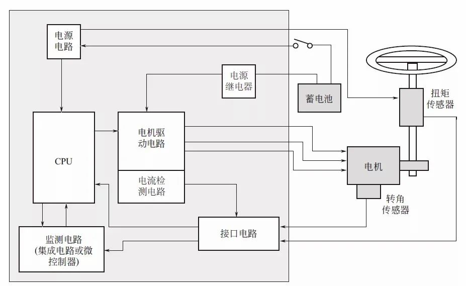
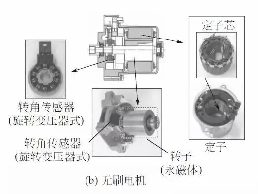
Composition and Working Principle of Electric Power Steering System (EPS)

Example of EPS ECU Circuit (Brushless)

The printed circuit board of EPS ECU is shown in the figure below, consisting of coils required to eliminate interference in the power line, electrolytic capacitors required to absorb current fluctuations, and power relays required to switch the power supply.Since the size of the printed circuit board must not be too large, some types of printed circuit boards are equipped with semiconductor relays.

Composition and Working Principle of Electric Power Steering System (EPS)

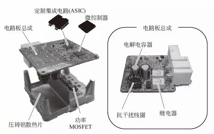
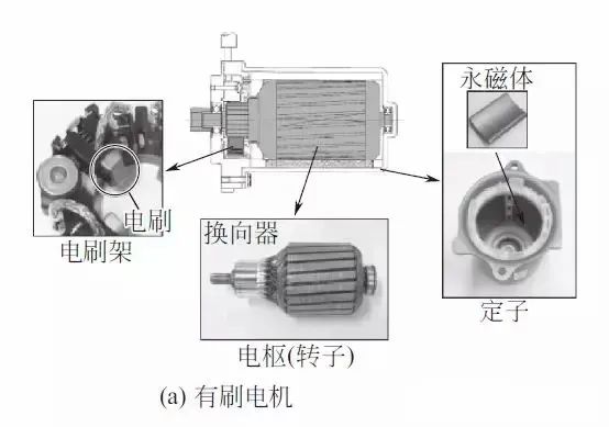
Example of EPS ECU Composition (Brushed)

5

Control

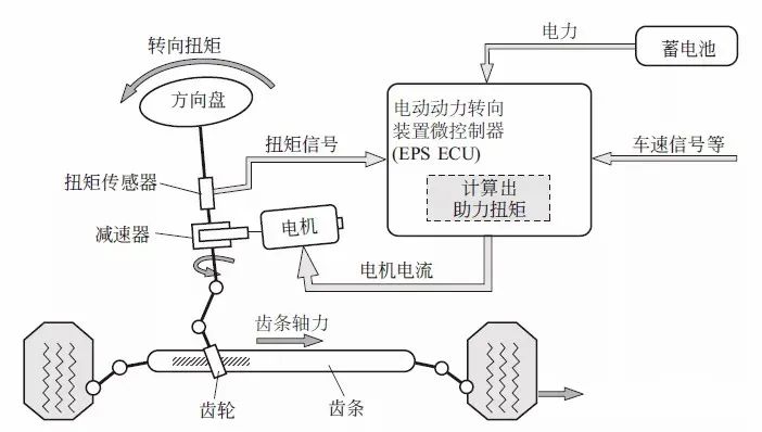
EPS assist control is shown in the figure below, which can be divided into basic assist control, assist auxiliary control, motor current control, and failure protection handling.Different manufacturers have different control methods, and common control methods will be explained here.

Composition and Working Principle of Electric Power Steering System (EPS)

Example of EPS Control
(1) Basic Assist Control
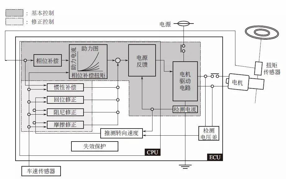
To compensate for the response delay of the system to the torque sensor signal, phase compensation should be implemented.Based on the value after phase compensation, the assist amount is determined.These controls are closely related to vehicle characteristics and are mostly set in graphical form.Additionally, assist amount can be adjusted based on vehicle speed, applying speed sensitivity characteristics.Then, the final assist command value is passed to the current control section by adding the auxiliary control amount.
(2) Assist Auxiliary Control
The steering wheel is not only controlled by the driver’s steering operation; when the road applies torque to the tires, the steering wheel may also rotate.Therefore, in addition to conventional basic assist control, assist auxiliary control should also be implemented.The main assist auxiliary controls include:“Inertia compensation” to smooth assist when excluding the motor’s inertia torque influence;corresponding return correction when the steering wheel returns due to restoring torque after turning;“Damping correction” to stabilize the steering wheel when letting go;and corresponding friction correction due to assist delay caused by friction in the motor or mechanism.
The correction amount is the same as the assist graph and is a value that changes based on vehicle characteristics, all of which should be determined after matching.
(3) Motor Current Control
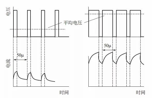
To enable the motor to track the above motor current command value in real-time, it is necessary to control the motor’s current.Typically, after detecting the motor current, the corresponding difference of the command value is corrected, i.e., feedback control.Additionally, based on half the cycle of the assist command value, the motor circuit control cycle is set.Basically, for the difference between the command value and the current detection value, PI (Proportional Integral) control can be implemented, converting it into a voltage command value, and this voltage command is converted into the PWM duty cycle, controlling the motor by switching MOSFET through this duty cycle.

Composition and Working Principle of Electric Power Steering System (EPS)

PWM Control (Brushed)
Moreover, when using brushless motors, motor current control is usually vector control for obtaining motor angle signals, and the d-axis and q-axis of the vector also need to undergo feedback PI control.
In addition to feedback control, some motor current controls also adopt observer control and model matching control.
(4) Failure Protection
To provide assist that is about ten times the driver’s steering force, EPS must quickly detect any abnormalities in assist and take accurate measures (see table below).

Composition and Working Principle of Electric Power Steering System (EPS)

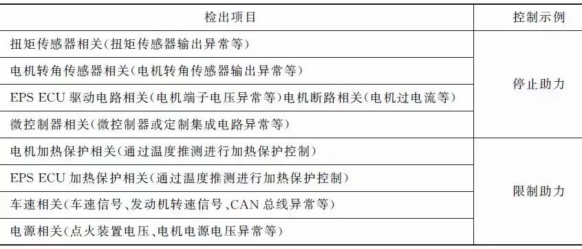
EPS should avoid not only abnormal overheating but also steering lock where the steering wheel cannot turn and free play where the steering wheel rotates freely.When an abnormal condition is detected, the system must be shut down.
Therefore, most EPS adopt a interlock method that monitors whether the direction of the driver’s steering torque matches the direction of the assist.However, EPS that works in conjunction with other systems has already been put into practical use, and the direction of assist may not necessarily match the direction of the steering torque, so in such systems, a method that monitors the control calculation itself is used.

(Image source from the internet)

Click the mini-program below to see more repair cases

Composition and Working Principle of Electric Power Steering System (EPS)

Leave a Comment