In this article, we will briefly compare the PWM output capabilities of Arduino and ESP32, and then use both to drive the same electronic speed controller (ESC).
1. PWM Output Function of Arduino
In Arduino, we can use the analogWrite() function to output PWM signals. This function has two parameters: pin and duty cycle (0-255). Note: Only pins marked with a ~ symbol support PWM output. Common PWM pins on Arduino boards (like Uno) are typically 3, 5, 6, 9, 10, and 11.
2. PWM Output Function of ESP32
ESP32 provides a flexible and powerful PWM (Pulse Width Modulation) capability through the LEDC (LED PWM Controller). It is important to note that ESP32 can also implement PWM in the same way as Arduino, but the default resolution is 8 bits (0 to 255).
1. Features of the LEDC Controller
16 independent channels (0-15): Be aware that channel 0 may be used by default, so it is recommended to start using from channel 5.
2 groups of timers: high-speed and low-speed, each with 4.
Adjustable frequency: 1Hz – 40MHz.
Programmable resolution: 1-20 bits.
Supports fading function: Smoothly change the duty cycle.
2. PWM Output Process
Configure the timer (frequency and resolution).
Connect the channel to the timer.
Attach the channel to the GPIO pin.
Set the duty cycle.
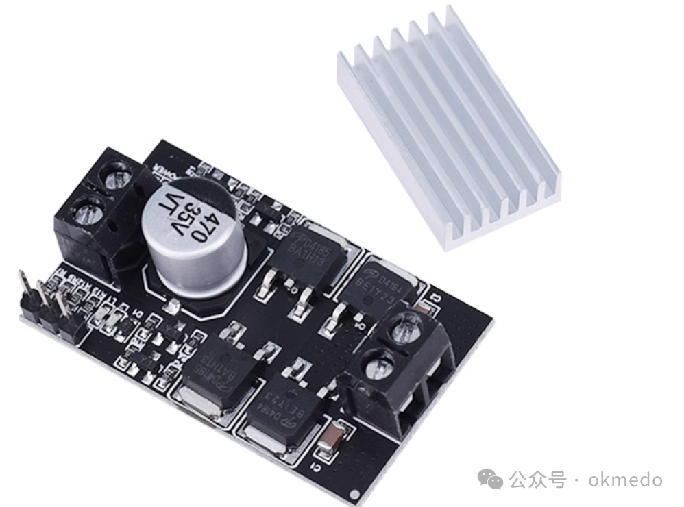
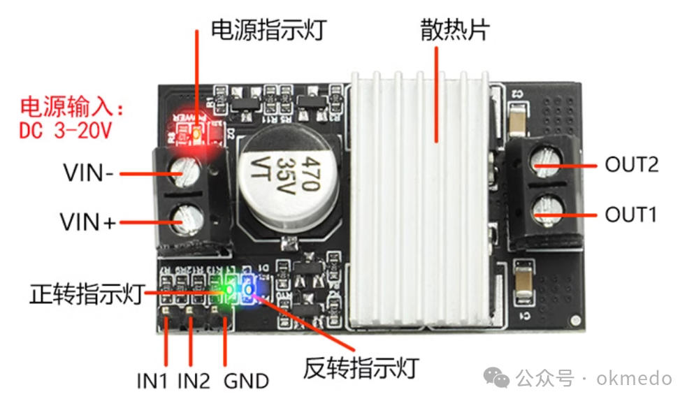
3. Introduction to XY-MC10 ESC
XY-MC10 is a PWM DC motor driver module with 5V, 12V, and 10A forward and reverse control switch, mainly used for speed regulation and dimming.
Usage Precautions
1. The power supply for the driver must not be reversed; it is recommended to connect a 15A fuse in series at the power interface. If the voltage is reversed, the driver module may burn out when powered on.
2. It is recommended to use PWM frequencies between 400Hz and 2kHz.
3. When changing the direction of the motor, it is necessary to stop or brake the motor first before changing direction (to avoid a sudden high current that could burn out the circuit). The braking or stopping time should be greater than 0.5 seconds; otherwise, the module may burn out.
4. The module power supply voltage is: 3V-20V.
5. Signal terminal supply voltage: 3V-20V.
6. Supports duty cycle range: 0-100%.
7. PWM frequency range: 400-2K.
8. Maximum peak current is 15A; for currents above 8A, it is recommended to add auxiliary heat dissipation. The maximum operating current is 10A.
4. Arduino Uno Driving XY-MC10 ESC
//AA AB connected to the direction motor of the car#define AA 6 #define AB 9//BA BB connected to the drive motor of the car#define BA 10 #define BB 11void setup() { Serial.begin(9600); // UNO recommends using 9600 baud rate pinMode(AA, OUTPUT); pinMode(AB, OUTPUT); pinMode(BA, OUTPUT); pinMode(BB, OUTPUT);}void loop() {analogWrite(BA,speed); // speed 0-255analogWrite(BB,0); //analogWrite(BA,0); // Below is for changing direction //analogWrite(BB,speed); } 5. ESP32 Driving XY-MC10 ESCIt is important to note that ESP32 can also implement PWM in the same way as Arduino, but the default resolution is 8 bits (0 to 255).
#define SERVO_PIN 15 // Servo signal line connected to GPIO15 Control direction#define MOTOR_A_A 16#define MOTOR_A_B 17//PWM configurationconst int PWM_FREQ=50; // 50Hz standard RC frequency// Common values 8 (0-255), 10 (0-1023), 12 (0-4095), 15 (0-32767), etc. Higher resolution allows for finer control but reduces the maximum available frequency.const int PWM_RESOLUTION=8;const int PWM_CHANNEL_A=5; // Use LEDC channel 0-15; 0 is used by the above SERVO_PINconst int PWM_CHANNEL_B=6;void setup() { Serial.begin(115200); // Optional: Set servo pulse width range (in microseconds) //myServo.attach(SERVO_PIN, 500, 2500); // Calibrate servo range myServo.attach(SERVO_PIN); // Bind servo pin myServo.write(95);//90 is vertical down (set according to actual situation) Left 120 Right 60 // Configure PWM channel ledcSetup(PWM_CHANNEL_A,PWM_FREQ, PWM_RESOLUTION); ledcSetup(PWM_CHANNEL_B,PWM_FREQ, PWM_RESOLUTION); // Attach PWM channel to GPIO pin ledcAttachPin(MOTOR_A_A,PWM_CHANNEL_A); ledcAttachPin(MOTOR_A_B,PWM_CHANNEL_B); // Initialize to keep the motor in a stopped state ledcWrite(PWM_CHANNEL_A,0); ledcWrite(PWM_CHANNEL_B,0); //prefs.begin("okmedo",false);// NVS storage note namespace start=== Do not forget ==bool begin(const char *namespace,bool readOnly=false); //pinMode(LED_Pin,OUTPUT); //WIFI_AP_INIT(); WIFI_STA_INIT(); websocket_init(); //server_init(); //prefs.end();// NVS storage note namespace end================================== Do not forget ===================}void loop() { if (Serial.available()) { temp=Serial.readStringUntil('\n'); // Read until newline character //0 degree position (minimum angle) //myServo.write(temp.toInt()); // Directly the angle 0-180 90 is in the middle speedChange(temp.toInt()); delay(1000); // Wait 1 second Serial.println(temp); } webSocket.loop(); }void speedChange(unsigned int fb){ //fb 10-90 unsigned int speed=0; if(fb>54) { // Starting point to 255 (the starting point is the tested initial value that the motor can start) This value range is related to the PWM_RESOLUTION setting above speed=map(fb,55,90,50,255); ledcWrite(PWM_CHANNEL_A,speed); ledcWrite(PWM_CHANNEL_B,0); } if(fb<46) { // Starting point to 255 (the starting point is the tested initial value that the motor can start) This value range is related to the PWM_RESOLUTION setting above speed=map(fb,45,10,50,255); ledcWrite(PWM_CHANNEL_A,0); ledcWrite(PWM_CHANNEL_B,speed); } if(fb>45&&fb<55) { ledcWrite(PWM_CHANNEL_A,0); ledcWrite(PWM_CHANNEL_B,0); } Serial.println("speed="+speed);}