Open the music and listen while watching☝ (Today’s recommendation: “Enough Time”)
Recently, a project I worked on involved BLDC motors, which I am also very interested in regarding motor control. Here, I will organize my study notes.
We have categorized motors according to the type of power supply and rotation principle (Figure 2). Let’s take a brief look at the characteristics and uses of various types of motors.
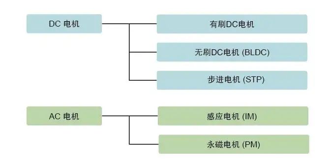
Figure 2: Main Types of Motors
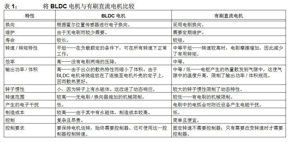
The simple and easy-to-control DC motor (brushed motor) is usually used in household appliances for purposes such as “opening and closing the CD tray”. It can also be used in cars for purposes like “opening and closing electric mirrors, steering control”, etc. Although it is cheap and can be used in multiple fields, it also has drawbacks. Due to the contact between the commutator and the brushes, its lifespan is short and the brushes must be replaced or serviced regularly.
The stepper motor rotates with the number of electrical pulses sent to it. Its movement depends on the number of electrical pulses sent, making it suitable for position adjustments. It is commonly used in households for tasks such as “paper feeding in fax machines and printers”. The feeding steps of the fax machine depend on specifications (pattern, fineness), making the stepper motor that rotates according to the number of electrical pulses very easy to use. It easily solves the problem of the machine temporarily stopping once the signal stops.
The synchronous motor, whose rotation speed changes with the power supply frequency, is used for purposes such as “the rotating table in microwaves”. The motor group has a gear reducer to achieve a rotation speed suitable for heating food. The induction motor is also affected by the power supply frequency, but the frequency and rotation speed are not consistent. Previously, this type of AC motor was used in fans or washing machines.
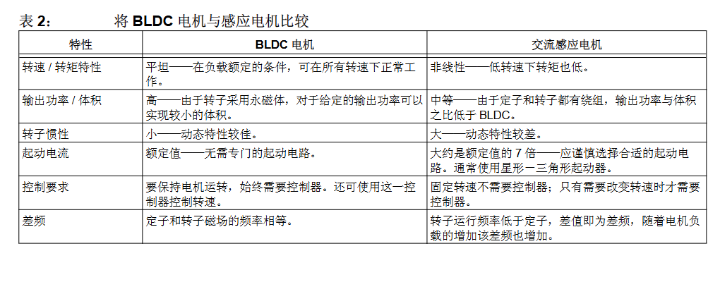
As can be seen, various types of motors are active in multiple fields. Among them, what characteristics does the BLDC motor (brushless motor) have that make it so widely used?
How BLDC Motors Rotate
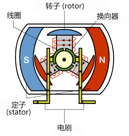
In BLDC motors, “BL” stands for “brushless”, meaning there are no brushes like in DC motors (brushed motors). The role of brushes in DC motors is to supply power to the coils in the rotor through the commutator. So how does a BLDC motor supply power to the coils in the rotor without brushes? It turns out that BLDC motors use permanent magnets to make the rotor, which does not have coils. Since there are no coils in the rotor, there is no need for a commutator and brushes for power supply. Instead, the coils act as the stator (Figure 3).
In DC motors (brushed motors), the magnetic field created by the fixed permanent magnets does not move, and the rotation is achieved by controlling the magnetic field generated within the coils (rotor). The rotation speed can be changed by altering the voltage. The rotor of a BLDC motor is a permanent magnet, and the rotor rotates by changing the direction of the magnetic field generated by the surrounding coils. The rotation of the rotor can be controlled by adjusting the direction and magnitude of the current flowing to the coils.
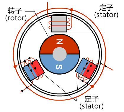
Figure 3: Schematic Diagram of BLDC Motor Operation.
BLDC motors use permanent magnets as rotors. Since there is no need to supply power to the rotor, brushes and commutators are not required. Control is done externally on the current supplied to the coils.
-
Brushed motors have issues such as sparks, radio interference, noise, and short lifespan due to wear from the brushes and commutator. Brushless DC motors (BLDC) do not use brushes for commutation, instead using electronic switches for commutation.
-
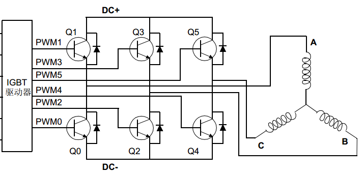
In hardware, brushless motors mainly use three-phase inverter circuits for driving.
-
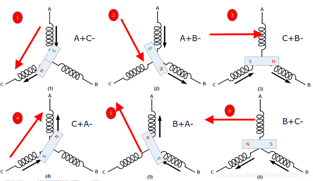
Brushless DC motors operate based on the interaction between the stator magnetic field and the rotor magnetic field. The direction of the magnetic field of each coil can be determined according to the right-hand rule, and the combined direction of two coils can be determined by vector synthesis. Thus, the three coils are connected to the DC power supply in a regulated manner by electronic switching elements, forming a rotating magnetic field that pulls the rotor to rotate, similar to a carrot hanging in front of a donkey.
-
It can be seen that the rotor has only 6 stable states in the magnetic field, and BLDC generally uses square wave drive, so the rotation of the BLDC is not actually *smooth. To solve this problem, multi-poles (number of magnetic poles) and multi-motor slots have emerged. For example, a two-pole BLDC motor can “shake” 12 times within 360°, instead of shaking 6 times, the more poles, the more **smooth it becomes, similar to the concept of calculus.
Internal Structure of Brushless DC Motor
The structure of the brushless DC motor is shown in the following figure (taking a slotted, outer rotor, sensorless motor as an example):
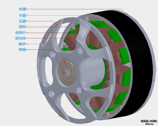
The above figure shows that the brushless motor consists of a front cover, middle cover, magnets, silicon steel sheets, enameled wire, bearings, rotor shaft, and rear cover. Among them, the magnets, bearings, and rotor shaft make up the rotor; the silicon steel sheets and enameled wire make up the stator; the front cover, middle cover, and rear cover form the motor housing. Important components are explained in the following table:

-
Rotor Description
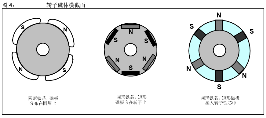
The rotor of the brushless DC motor (BLDC) is made of permanent magnets, with multiple pairs of magnetic poles arranged alternately (involving pole pair parameters).
-
Stator Description
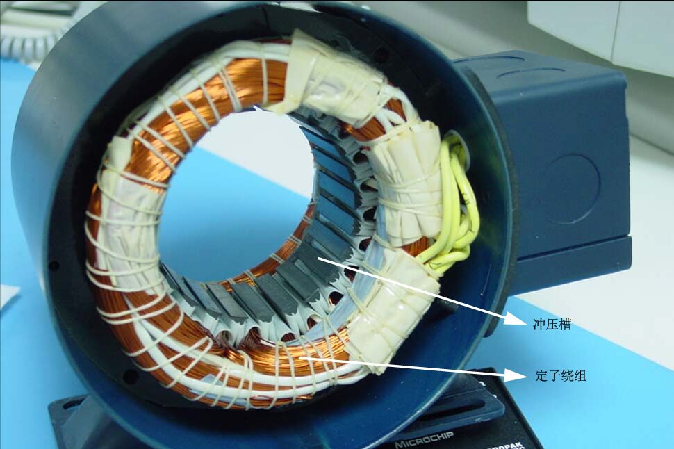
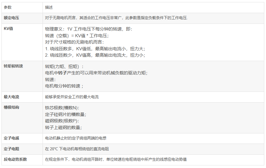
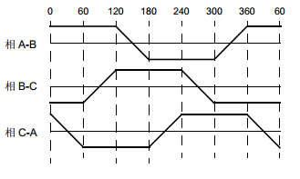
The stator of the brushless DC motor (BLDC) is made of silicon steel sheets (as shown in the following figure), and the stator windings are placed in slots axially along the inner shaft (involving core pole numbers (slot number N) parameters). Each stator winding is made up of many interconnected coils. Common winding distribution is in a three-phase star configuration.
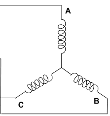
Three-phase star-connected winding coils can be divided into trapezoidal and sinusoidal wave windings based on the connection method. The main difference between the two is the waveform of the back EMF produced. As the name suggests: trapezoidal stator windings produce trapezoidal back EMF, while sinusoidal windings produce sinusoidal back EMF. As shown in the following figure:
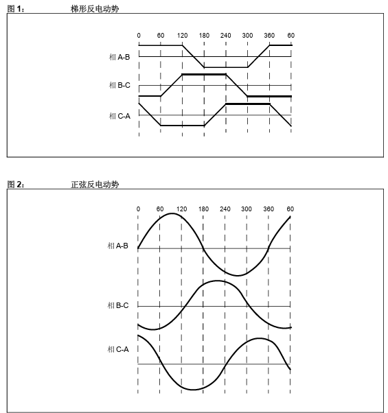
PS: When the motor is powered without load, the waveform can be measured using an oscilloscope.
Description of Brushless DC Motor Classification
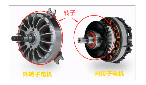
Brushless DC motors (BLDC) can be classified into inner rotor motors and outer rotor motors based on rotor distribution; they can be classified into single-phase motors, two-phase motors, and three-phase motors (most commonly used) based on drive phases; they can be classified into sensored and sensorless motors based on whether they are equipped with sensors, etc.; there are many classifications for motors, and due to space constraints, this will not be elaborated here. Interested readers can learn more on their own.
-
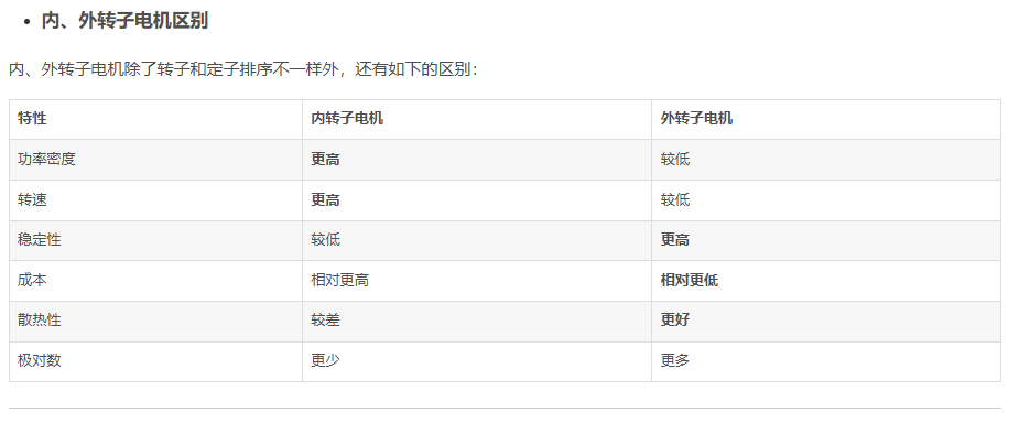
Inner and Outer Rotor Motor Description
Brushless motors can be divided into outer rotor motors and inner rotor motors based on the structural arrangement of the rotor and stator (as shown in the following figure).

Brushless Motor Parameters
Differences Between BLDC and PMSM#
Brushless motors are mainly divided into two types: BLDC and PMSM.
The former is referred to as Brushless Direct Current Motor (BLDC), while the latter is known as Permanent Magnet Synchronous Motor (PMSM).
They have similar structures, both having permanent magnet rotors and wound stators. BLDC is also a synchronous motor, but due to the different interconnection methods of the stator windings, they produce different back EMFs. The voltage drop across the windings can be calculated by subtracting the back EMF from the supply voltage.
-
BLDC has a trapezoidal back EMF.
-
PMSM has a sinusoidal back EMF.
Thus, we can distinguish between these two types of motors.
From a software control perspective, generally speaking,
-
BLDC uses 6-step square wave driving, but some BLDC can also use FOC driving. For more details, refer to https://www.zhihu.com/question/50312245, which will be analyzed in detail later.
-
PMSM uses FOC (Field Oriented Control) driving.
Both types of motors have their advantages.
-
BLDC is 15% more powerful compared to PMSM in terms of power density and torque inertia ratio.
-
PMSM has advantages in cogging torque, harmonic components, etc.
-
PMSM has a more complex stator manufacturing process, resulting in higher costs.
PMSM will be analyzed in detail later.
Hall Sensors#
BLDC uses the sequential conduction of electronic switches to energize the stator windings in order, forming a rotating magnetic field that pulls the permanent magnet rotor into motion. So when should each pair of switches be turned on? When should each pair of windings be energized? To answer this, we first need to know which of the 6 states the rotor is currently in, which requires a rotor position detection device. Currently, photoelectric devices and Hall devices are mainly used. Since I have a Hall sensor on hand, the experiment will focus on Hall sensors.
The principle of Hall sensors:
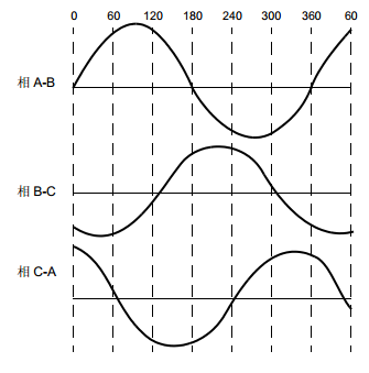
It is based on the Hall effect: when a magnetic field perpendicular to the direction of current is applied to a semiconductor, the electrons and holes in the semiconductor experience different Lorentz forces (left-hand rule) and accumulate in different directions, creating an electric field between the accumulated electrons and holes. When the electric field force balances the Lorentz force, they stop accumulating, and the electric field will cause subsequent electrons and holes to be balanced against the Lorentz force generated by the magnetic field, allowing them to pass through without deviation. This phenomenon is called the Hall effect, and the generated internal voltage is called the Hall voltage.
When the direction of the current remains unchanged and the direction of the magnetic field changes, the Hall voltage changes accordingly.
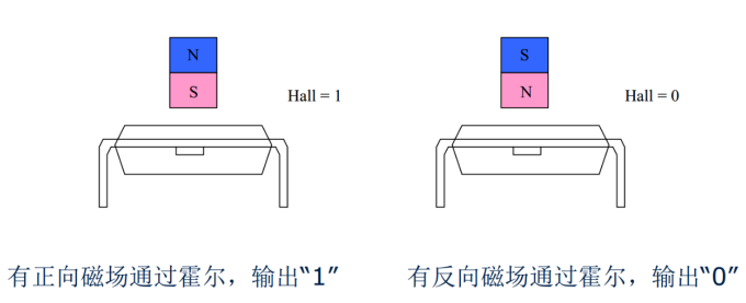
Some BLDC motors may embed three Hall sensors in the stator (which is complex and costly), while others may install the Hall sensor on a separate PCB and place the Hall sensor magnet on the rotor (which is cheaper). Whenever the rotor magnetic poles pass by the Hall sensor, the Hall sensors will output high and low signals. Based on the combination of the three Hall signals, we can determine the position of the rotor.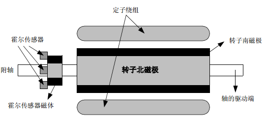 Based on the installation position of the Hall sensor, the phase shift between the output signals can be 60° or 120°.
It is important to note that the 60° installed Hall sensors will produce 000 and 111, while the 120° installation will not. This point can be used to differentiate between 60° and 120° installations.
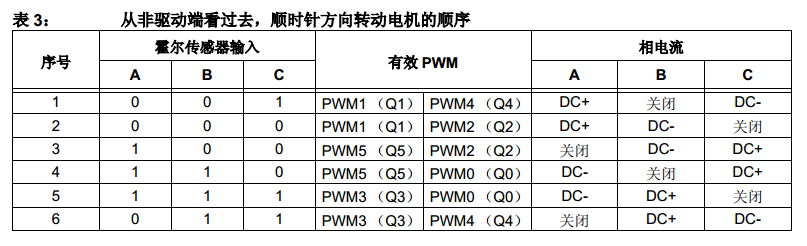
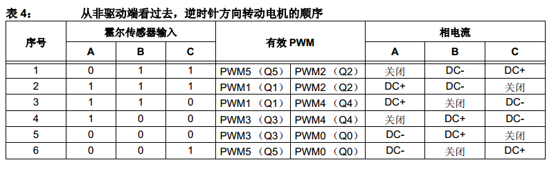
Generally, motor manufacturers will define the commutation timing that should be followed based on Hall installation. For example:
If the motor manufacturer does not provide a timing table, one can only derive it through experimentation (which can be quite frustrating).
Hardware Driving Solutions#
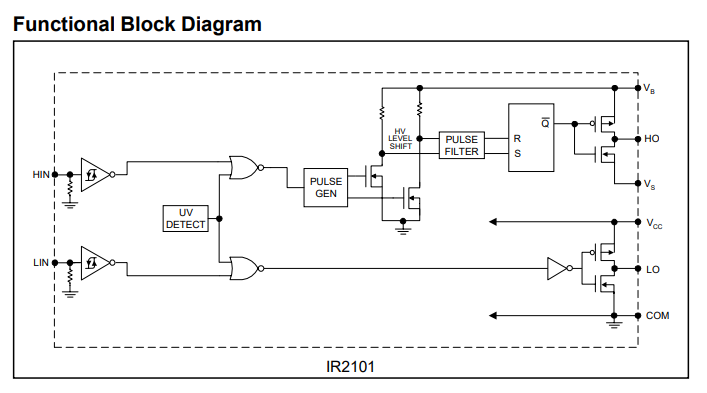
For the hardware driving solution, I chose the IR2101 to drive the PSMN011-80YS, and the MCU is the ST f103. The 6 PWM signals are provided by the advanced timer TIM1 of the f103, and this part can be connected according to logical requirements.
Taking one of the driving parts as an example, an opto-isolator was added between the f103 and IR2101. Of course, it can also be driven directly without adding it. IR2101 supports 3.3V logic input, and the purpose of adding it is mainly to prevent damage to the main control part even if the subsequent circuit is damaged.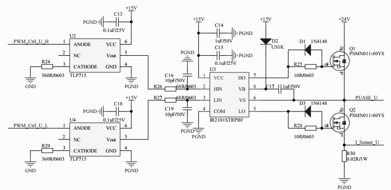 IR2101 internally performs high-side driving processing, and just adding a capacitor and a diode outside can form a boost driving circuit, which simplifies many troubles. Of course, other IR series can also be chosen to drive the 6 MOSFETs directly, and there are also many integrated solutions (though they tend to be expensive).
Principle Analysis:
-
Based on our previous analysis, at any given time, two MOSFETs will be on simultaneously, energizing two windings.
-
When the lower bridge N-MOS is turned on, the S terminal is grounded, so as long as Ugs>Uth
𝑈 𝑔 𝑠 > 𝑈 𝑡 ℎ -
We let the corresponding lower bridge arm turn on first, applying a PWM wave to the upper bridge N-MOS, which turns on at high voltage. However, after it turns on, the S terminal becomes 24V, so we need 24+Uth
24 + 𝑈 𝑡 ℎ 𝑉 𝐵 15 𝑉 to ideally generate a voltage of about 15+24=39V15 + 24 = 39 𝑉 (in reality, the voltage will be lower due to the voltage drop across the MOSFET), this 39V voltage will drive the H0𝐻 0 of the IR2101, ensuring that it can conduct normally during the high voltage period. Diode D2 mainly serves to allow unidirectional conduction.
 It is important to note that if the manufacturer of the Hall sensor has not treated the internal output, it may be OC/OD output, and a pull-up resistor must be added to output a high signal. If the GPIO port of the MCU is not 5V compatible, a Schottky diode can be added to pull up to a 3.3V clamp for protection.
Advantages of BLDC Motors
BLDC motors have three coils on the stator, each with two wires, totaling six lead wires in the motor. In reality, due to internal wiring, only three wires are typically needed, but it is still one more than the previously mentioned DC motors (brushed motors). Simply connecting the positive and negative terminals of the battery will not cause any movement. How to operate the BLDC motor will be explained in the second part of this series. For now, we will focus on the advantages of BLDC motors.
The first characteristic of BLDC motors is “high efficiency”. It can control its torque to always maintain maximum value. In contrast, the maximum torque of DC motors (brushed motors) can only be maintained for a brief moment during rotation and cannot consistently stay at maximum value. If a DC motor (brushed motor) wants to achieve the same torque as a BLDC motor, it must increase its magnets. This is why even small BLDC motors can produce powerful forces.
The second characteristic is “good controllability”, which is related to the first. BLDC motors can precisely achieve the desired torque, rotation speed, etc. They can accurately feedback target rotation speed, torque, etc. Through precise control, motor heating and power consumption can be suppressed. If battery-driven, careful control can extend driving time.
Additionally, they are durable and produce low electrical noise. The above two points are advantages brought by the absence of brushes. In contrast, DC motors (brushed motors) experience wear due to contact between brushes and commutators over long periods of use. The contact parts can also create sparks. Especially, when the commutator’s gaps meet the brushes, huge sparks and noise can occur. If noise is not desired during operation, one would consider using a BLDC motor.
Where BLDC Motors Are Used
BLDC motors, known for their high efficiency, diverse control, and long lifespan, are typically used in products that can leverage these characteristics and are used continuously. For example: household appliances. People have been using washing machines and air conditioners for a long time. Recently, BLDC motors have also started to be used in electric fans, successfully leading to a significant reduction in power consumption. It is precisely because of their high efficiency that power consumption has decreased.
BLDC motors are also used in vacuum cleaners. In one case, by changing the control system, a significant increase in rotation speed was achieved. This case illustrates the good controllability of BLDC motors.
As an important storage medium, hard disks also use BLDC motors for their rotating parts. Since these motors need to operate for long periods, durability is crucial. Of course, they also serve the purpose of significantly suppressing power consumption. Here, high efficiency is also related to low power consumption.
BLDC Motors Have Many Other Applications
BLDC motors are expected to be applied in even broader fields. They are likely to be widely used in small robots, especially in service robots that provide services outside of manufacturing. “Isn’t it better to use stepper motors that operate with the number of electrical pulses for positioning?” some might wonder. However, BLDC motors are more suitable for force control. Moreover, if stepper motors are used, significant current must be provided to keep structures like robotic wrists fixed in a specific position. In contrast, BLDC motors can provide only the required power in conjunction with external forces, thereby suppressing power consumption.
They are also applicable in transportation. Traditionally, simple DC motors have been used in electric vehicles for the elderly or golf carts, but recently, high-efficiency BLDC motors with good controllability have begun to be adopted. Fine control can extend the duration of battery life. BLDC motors are also suitable for drones. Especially in multi-rotor drones, precise control of rotation is advantageous as it controls flight posture by changing the rotation speed of the propellers.
Note: The views expressed in this article are solely those of the author and do not guarantee or promise the content. Readers are advised to refer only for reference and verify the authenticity and legality on their own. If you find that the source of the images, text, or videos is incorrectly marked or infringes on your rights, please inform us, and we will promptly modify or delete them.