Select “GuaGua Little Master” at the top, choose “Pin/Star Public Account“
Useful content delivered promptly!

Summary: For microcontroller programs, everyone is familiar, but not many truly consider the architecture. With the continuous increase in program development, architecture is very necessary.
There are roughly three architectures for applications:
1. Simple front and back sequential execution program, this writing method is used by most people, without the need to think about the specific architecture of the program, just write the application program directly through the execution order.
2. Time-slice polling method, this method is an approach between sequential execution and operating systems.
3. Operating system, this method should be the highest realm of application program writing.
1. Program Framework Design
1. Front and back sequential execution method
This is a commonly used program framework design scheme for beginners, without needing to consider too many things, the code is simple, or the overall real-time and concurrency requirements of the system are not high; after initialization, it continuously calls the functions written by itself through <span>while(1){}</span> or <span>for(;;)</span>{}` loop, and generally does not consider the time required for each function execution, most of the time there are milliseconds of delay waiting in the functions.
-
Advantages: For beginners, this is the easiest and most intuitive program architecture, with simple and clear logic, suitable for software development with simple logic and lower complexity.
-
Disadvantages: Low real-time performance, as each function has milliseconds of delay, even if it is 1ms, it will cause different execution intervals between other functions. Although it can be done through timer interrupts, the premise is that the time taken by the interrupt execution function must be short. When the complexity of the program logic increases, it will lead to confusion for later maintainers, making it difficult to clarify the program’s running state.
The following is part of the code for the dormitory anti-theft system done during school (there were also some bugs at that time that were not resolved. Looking back now, there are actually many problems, and quite serious ones, such as a 3000ms delay in the interrupt service function, which is too scary, and serial port sending, etc.; since the real-time requirement is not very high, the millisecond-level delay in the main function does not have much impact on system operation, of course excluding bugs; if maintenance is needed later, it would be a big project, it would be better to rewrite it):
int main(void)
{
  u8 temperature;
  u8 humidity;
 int a;
 delay_init();
 NVIC_PriorityGroupConfig(NVIC_PriorityGroup_2);
  I2c_init();
 uart2_Init(9600);
 uart_init(9600);//Serial port initialized to 115200
 TIM3_Int_Init(4999,7199);
 ds1302_init();
 while(DHT11_Init())//DHT11 initialization
 {
  led2=0;
 }
 a1602_init();
  Ds1302Init();
 EXTIX_Init();
 GPIOX_Init();
 lcd12864_INIT();
 LcdInit();
 beep_init();
 RED_Init();
 led1=1;
 beep=0;
 while(1)
 {
  for(a=0;a<11;a++)
  {
   num[a+3]=At24c02Read(a+2)-208;
   delay_us(10);
  }
  for(a=0;a<6;a++)
  {
   shuru[a]=At24c02Read(a+13)-208;
   delay_us(10);
  }
  delay_ms(10);
  RED_Scan();
  Ds1302ReadTime();  //Read date and time of ds1302
  shi=At24c02Read(0); //Read saved alarm data
  delay_ms(10);
  fen=At24c02Read(1); //Read saved alarm data
  usart2_scan();   //Bluetooth data scanning
  usart2_bian();   //Bluetooth processing data
  usart2_gai();
  nao_scan();
  k++;
  if(k<20)
  {
   if(k==1)
    LcdWriteCom(0x01);//Clear screen
    LcdDisplay();     //Display date and time
  }
  if(RED==0)
     RED_Scan();
  if(k>=20&&k<30)
  {
   if(k==20)
    LcdWriteCom(0x01); //Clear screen
   Lcddisplay(); //Display temperature and humidity
   LcdWriteCom(0x80+6);
   DHT11_Read_Data(&&temperature,&&humidity); //Read temperature and humidity values
   Temp=temperature;Humi=humidity;
   LcdWriteData('0'+temperature/10);
   LcdWriteData('0'+temperature%10);
   LcdWriteCom(0x80+0X40+6);
   LcdWriteData('0'+humidity/10);
   LcdWriteData('0'+humidity%10);
  }
  if(k==30)
   k=0;
  lcd12864(); //Display anti-theft alarm status
 }
}

//Timer 3 interrupt service program
void TIM3_IRQHandler(void)//TIM3 interrupt
{
 int i;
 if(TIM_GetITStatus(TIM3, TIM_IT_Update) != RESET) //Check if TIM3 update interrupt has occurred
 {
  TIM_ClearITPendingBit(TIM3, TIM_IT_Update);//Clear TIMx update interrupt flag
  if(key1==1&&FEN-fen==0&&SHI-shi==0)//Alarm rings when time is up
  {
    f=1;
  }
  if(key1==0||FEN-fen!=0||SHI-shi!=0)
  else
  {
    f=0;
  }
   if(USART_RX_BUF[0]=='R'&&USART_RX_BUF[1]=='I'&&USART_RX_BUF[2]=='N'&&USART_RX_BUF[3]=='G')
  {
   key0=1;
   for(i=0;i<17;i++)
   {
    USART_SendData(USART1, num[i]);//Send data to serial port 1
    while(USART_GetFlagStatus(USART1,USART_FLAG_TC)!=SET);//Wait for send to finish
    USART_RX_STA=0;
   }
   delay_ms(3000);
   for(i=0;i<3;i++)
   {
    USART_SendData(USART1, num1[i]);//Send data to serial port 1
    while(USART_GetFlagStatus(USART1,USART_FLAG_TC)!=SET);//Wait for send to finish
    USART_RX_STA=0;
   }
  }
 }
}
2. Time-slice polling method
This is a program architecture design scheme between front and back sequential execution method and operating system. This design scheme can help embedded software developers to take it to the next level. In the embedded software development process, if the following points are encountered, then this design scheme can be said to be the optimal choice, suitable for more complex embedded systems:
-
The current requirement design does not need to use an operating system at all. -
Task functions do not need to be executed all the time, and there are intervals (for example, for buttons, software debouncing is generally needed, the usual approach for beginners is to delay about 10ms before judging, but 10ms greatly wastes CPU resources, during this time the CPU can handle many other tasks) -
Real-time performance has certain requirements.
This design scheme requires the use of a timer, usually set to 1ms (the timing can be set arbitrarily, but if the interrupt is too frequent the efficiency is low, and if the interrupt is too long, the real-time performance is poor), therefore it is necessary to consider the execution time of each task function, it is recommended not to exceed 1ms (if the execution time can be shortened through program optimization, that would be best; if it cannot be optimized, it must ensure that the execution cycle of that task is far greater than the time consumed by the task), and it is also required that there should be no millisecond-level delays in the main loop or task functions.
“
How to determine the task cycle of each function? It is determined based on the task’s execution time and effects, for example, the task cycle for button scanning is 10ms (to improve response), the task cycle for indicator light control is 100ms (usually a maximum flashing frequency of 100ms is just right, except for special requirements), and the LCD/OLED display cycle is 100ms (the time consumed through interfaces such as SPI/IIC is about 1~10ms, or even longer, so the task cycle must be much greater than the time consumed, and also to meet the screen refresh effect acceptable to the human eye, a task cycle of 100ms is more appropriate).
”
The following introduces two different implementation schemes, for friends without the concept of function pointers and for those who want to learn further.
1. Design method without function pointers
/**
  * @brief      Main function.
  * @param      None.
  * @return     None.
  */

int main(void)
{
    System_Init();

    while (1)
    {
        if (TIM_1msFlag)// 1ms
        {
            CAN_CommTask(); // CAN send/receive communication task

            TIM_1msFlag = 0;
        }
        if (TIM_10msFlag)  // 10ms
        {
            KEY_ScanTask(); // Button scanning processing task

            TIM_10msFlag = 0;
        }
        if (TIM_20msFlag) // 20ms
        {
            LOGIC_HandleTask();// Logic processing task

            TIM_20msFlag = 0;
        }
        if (TIM_100msFlag) // 100ms
        {
            LED_CtrlTask(); // Indicator light control task

            TIM_100msFlag = 0;
        }
        if (TIM_500msFlag)// 500ms
        {
            TIM_500msFlag = 0;
        }
        if (TIM_1secFlag) // 1s
        {
            WDog_Task(); // Feed dog task
            TIM_1secFlag = 0;
        }
    }
}

/**
  * @brief      Timer 3 interrupt service function.
  * @param      None.
  * @return     None.
  */
void TIM3_IRQHandler(void)
{
    if(TIM_GetITStatus(TIM3,TIM_IT_Update) == SET) //Overflow interrupt
    {
        sg_1msTic++;
        sg_1msTic % 1 == 0 ? TIM_1msFlag = 1 : 0;
        sg_1msTic % 10 == 0 ? TIM_10msFlag = 1 : 0;
        sg_1msTic % 20 == 0 ? TIM_20msFlag = 1 : 0;
        sg_1msTic % 100 == 0 ? TIM_100msFlag = 1 : 0;
        sg_1msTic % 500 == 0 ? TIM_500msFlag = 1 : 0;
        sg_1msTic % 1000 == 0 ? (TIM_1secFlag  = 1, sg_1msTic = 0) : 0;
    }
    TIM_ClearITPendingBit(TIM3,TIM_IT_Update);  // Clear interrupt flag
}
2. Design method with function pointers
/**
  * @brief Definition of task function related information structure.
  */
typedef struct{
    uint8 m_runFlag;                 /*!< Program running flag: 0-not running, 1-running */
    uint16 m_timer;                  /*!< Timer */
    uint16 m_itvTime;                /*!< Task running interval time */
    void (*m_pTaskHook)(void);       /*!< Task function to be run */
} TASK_InfoType;

#define TASKS_MAX     5              // Define the number of tasks

/** Task function related information */
static TASK_InfoType sg_tTaskInfo[TASKS_MAX] = {
    {0, 1, 1, CAN_CommTask},         // CAN communication task
    {0, 10, 10, KEY_ScanTask},       // Button scanning task
    {0, 20, 20, LOGIC_HandleTask},   // Logic processing task
    {0, 100, 100, LED_CtrlTask},     // Indicator light control task
    {0, 1000, 1000, WDog_Task},      // Feed dog task
};

/**
  * @brief      Task function running flag processing.
  * @note       This function is called by the 1ms timer interrupt
  * @param      None.
  * @return     None.
  */
void TASK_Remarks(void)
{
    uint8 i;
    for (i = 0; i < TASKS_MAX; i++)
    {
        if (sg_tTaskInfo[i].m_timer)
        {
            sg_tTaskInfo[i].m_timer--;
            if (0 == sg_tTaskInfo[i].m_timer)
            {
                 sg_tTaskInfo[i].m_timer = sg_tTaskInfo[i].m_itvTime;
                 sg_tTaskInfo[i].m_runFlag = 1;
            }
        }
   }
}

/**
  * @brief      Task function running processing.
  * @note       This function is called by the main loop
  * @param      None.
  * @return     None.
  */
void TASK_Process(void)
{
    uint8 i;
    for (i = 0; i < TASKS_MAX; i++)
    {
        if (sg_tTaskInfo[i].m_runFlag)
        {
             sg_tTaskInfo[i].m_pTaskHook();         // Run task
             sg_tTaskInfo[i].m_runFlag = 0;         // Clear flag
        }
    }
}

/**
  * @brief      Main function.
  * @param      None.
  * @return     None.
  */
int main(void)
{
    System_Init();
    while (1)
    {
        TASK_Process();
    }
}

/**
  * @brief      Timer 3 interrupt service function.
  * @param      None.
  * @return     None.
  */
void TIM3_IRQHandler(void)
{
    if(TIM_GetITStatus(TIM3,TIM_IT_Update) == SET) //Overflow interrupt
    {
        TASK_Remarks();
    }
    TIM_ClearITPendingBit(TIM3,TIM_IT_Update);// Clear interrupt flag
}
3. Operating System
The embedded operating system EOS (<span>Embedded OperatingSystem</span>) is a widely used system software, which was mainly used in industrial control and defense systems in the past. For microcontrollers, commonly used ones include UCOS, FreeRTOS, <span>RT-Thread</span> Nano, and RTX among many preemptive operating systems (other operating systems like Linux are not suitable for microcontrollers)
In terms of task execution, operating systems and <span>time-slice polling method</span> do not have too many requirements on the execution time of each task, and need to set the priority of each task. When a high-priority task is ready, it will preempt a low-priority task; operating systems are relatively complex, so they are not detailed here.
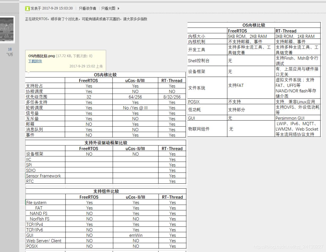
About how to choose a suitable operating system (<span>uCOS</span>, <span>FreeRTOS</span>, <span>RTThread</span>, <span>RTX</span> and other RTOS comparisons and characteristics:
-
uCOS: Rich online resources, very suitable for learning, but requires payment for product use. -
FreeRTOS: Free to use, therefore many products are using it. -
RT-Thread: Domestic IoT operating system, with a wealth of components, also free, documentation available at: RT-Thread Document Center. -
RTX: A royalty-free, deterministic real-time operating system designed for ARM and Cortex-M devices.
Here is a comparison image from the internet:
4. Conclusion
From the above comparison, it can be seen that the advantages of the time-slice polling method are quite large, as it has the advantages of both the front and back sequential execution method and the operating system. The structure is clear, simple, and very easy to understand, so this is a commonly used microcontroller design framework.
Original link: https://blog.csdn.net/qq_24130227/article/details/87537036
Copyright statement: This article is sourced from the internet, freely conveying knowledge, and the copyright belongs to the original author. If there are copyright issues, please contact me for deletion.
