Introduction to the Development Board:
1. The development board used is: ESP32-CAM
2. Camera module:OV2640
3. Programming base: ESP32-CAM development board programming base
4. Micro USB cable, 30cm with four wires
5. Schematic diagram of the development board
Preparation work for the project
Arduino official website: Arduino – Home https://www.arduino.cc/
1. Go to the website and select Software to download the software
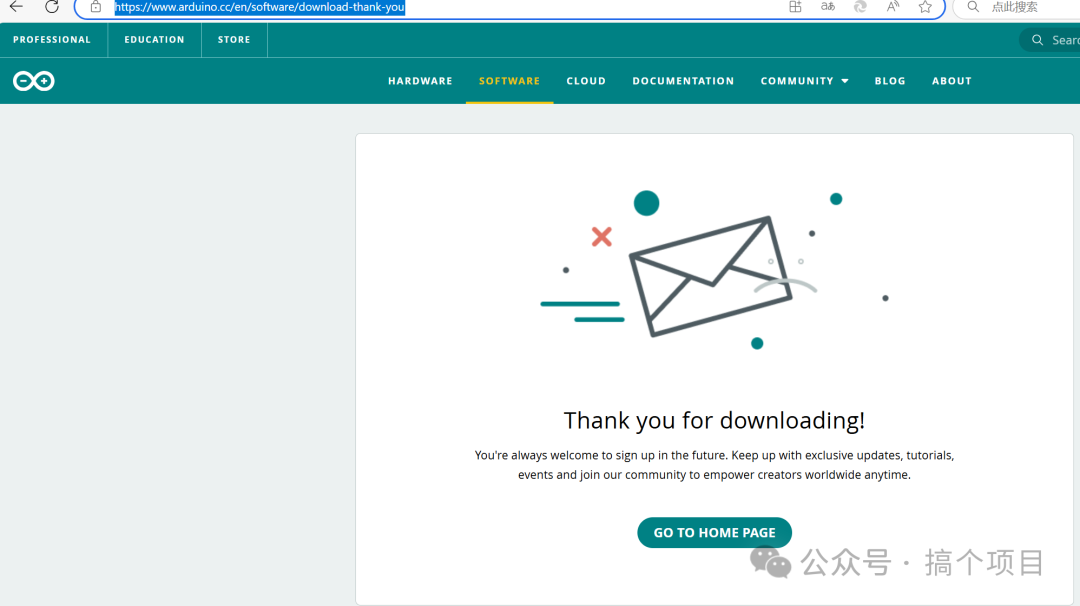
2. After the installation is complete, configure the software
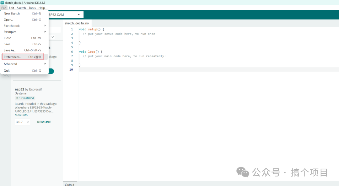
3. We need to enter the URLs in this field
https://arduino.esp8266.com/stable/package_esp8266com_index.json
https://dl.espressif.cn/dl/package_esp32_index.json
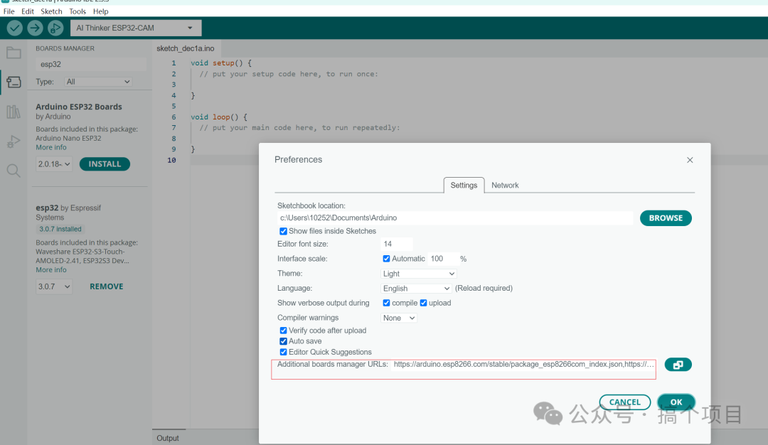
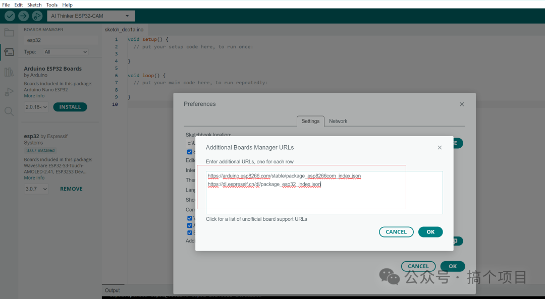
4. Download the corresponding support package for the development board. This process may take a while. I have uploaded the packaged files to Baidu Cloud, and you can download them directly and place them in the corresponding folder. The version I downloaded is esp32 by Espressif 3.0.7
Baidu Cloud: https://pan.baidu.com/s/1cqPI1Mn5Vq33LAEi9oBEWw?pwd=39sy Extraction code: 39sy
File location:
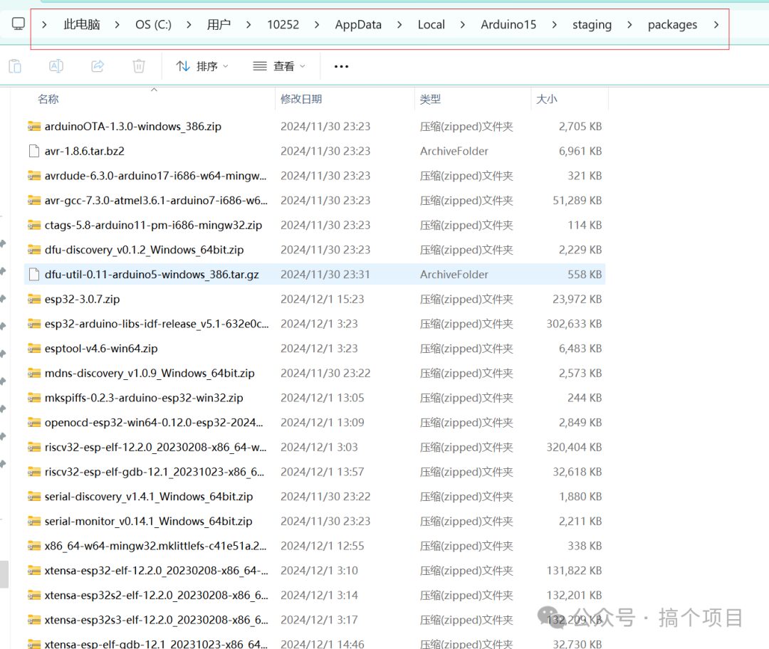
You can also use the built-in program of Arduino to download, the steps are as follows:
5. Find the board manager
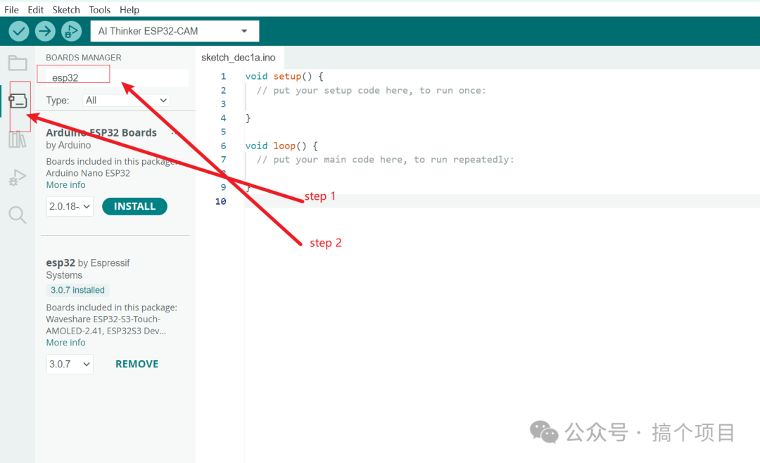
6. Search for esp32 on the search page and install the corresponding package. Here we install esp32 by Espressif 3.0.7
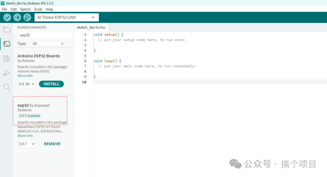
Now we have completed the environment setup required for the project, and we will start programming the board
II. Programming
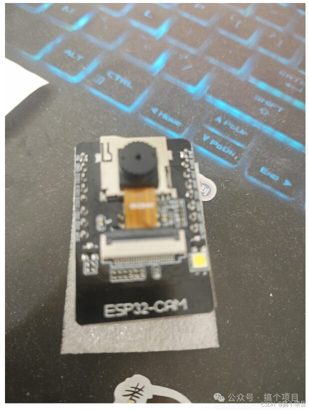
1. Connect the ESP32-CAM and the ESP32-CAM development board programming base together, and install the camera module OV2640 in the corresponding place on the development board. It looks something like the image below
 Edit
Edit
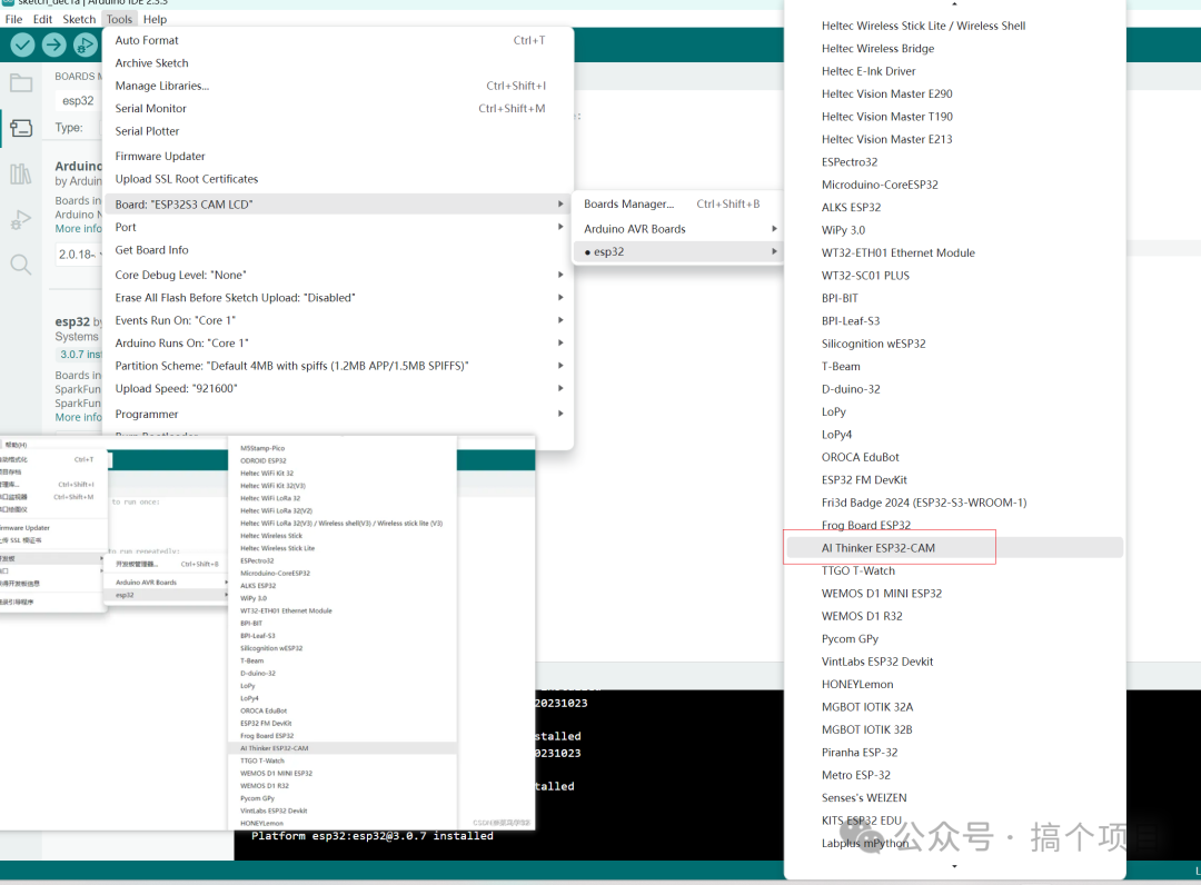
2. Connect the assembled development board to the computer and select the corresponding board support option in Arduino. Here we select AI Thinker ESP32-CAM
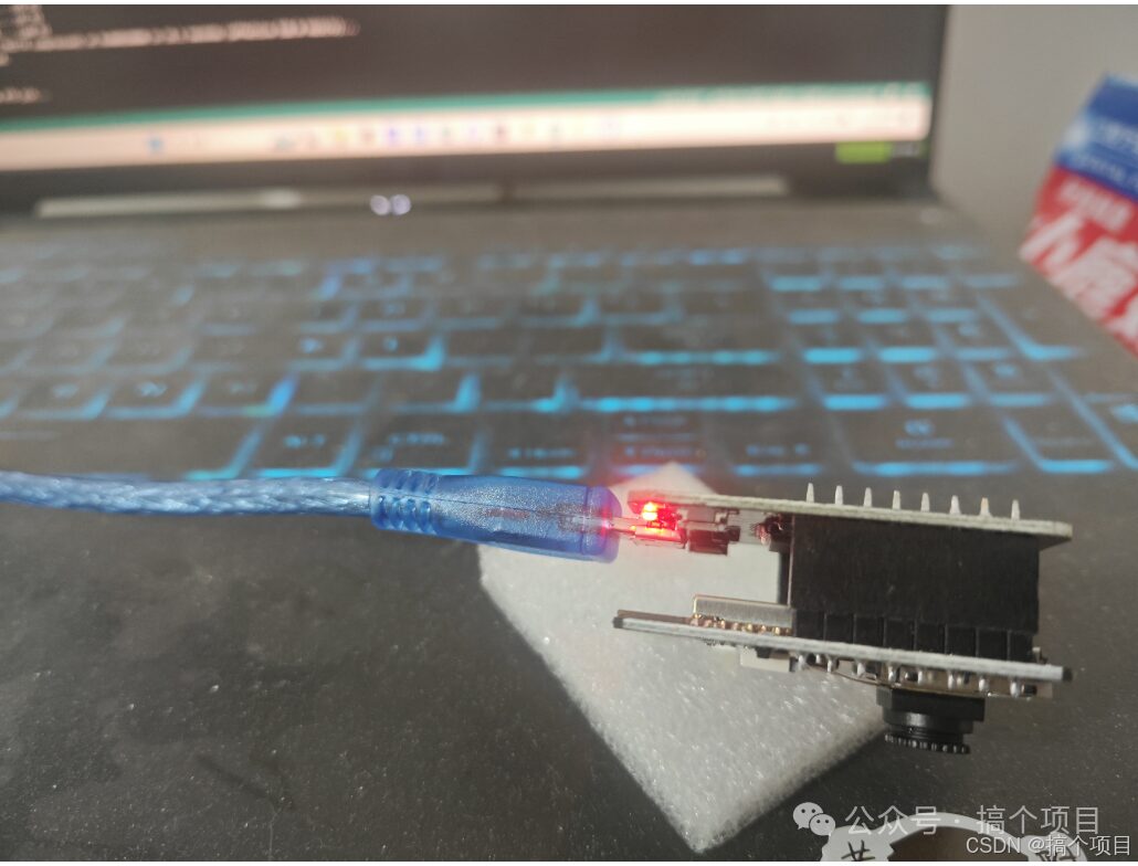
3. Once connected, the LED light on the board will light up
 Edit
Edit
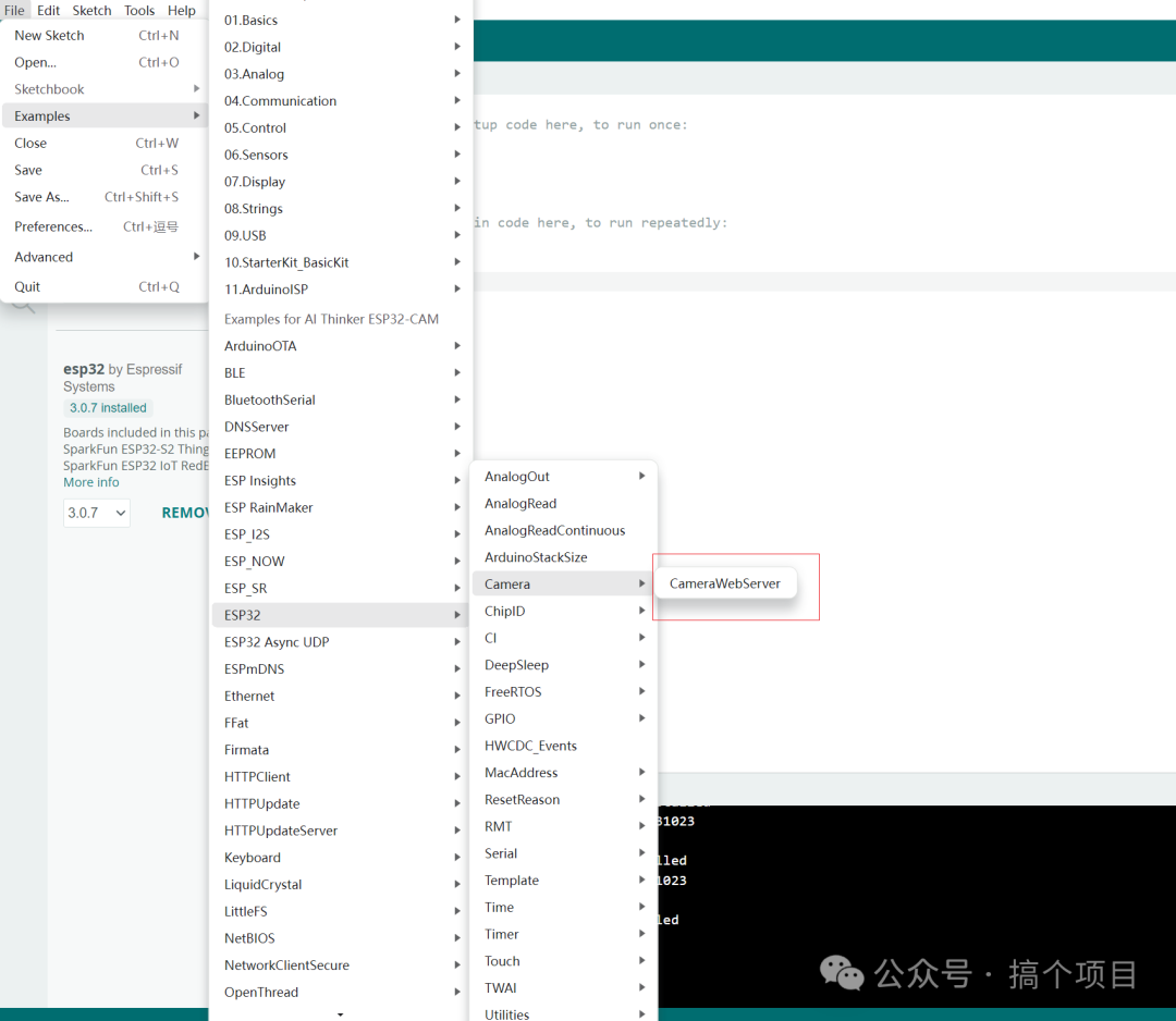
4. Select the example code to upload
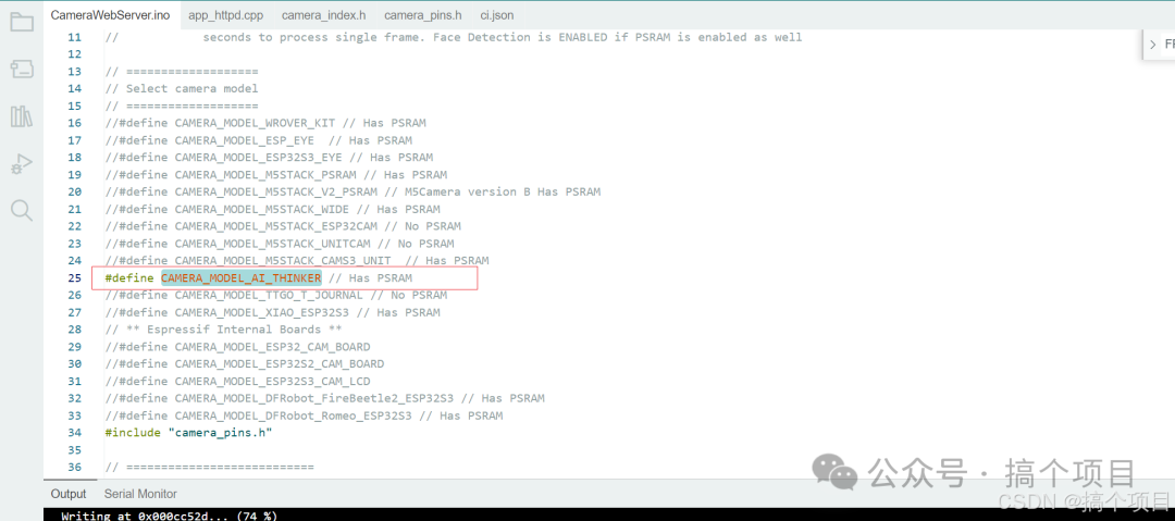
5. Modify the program
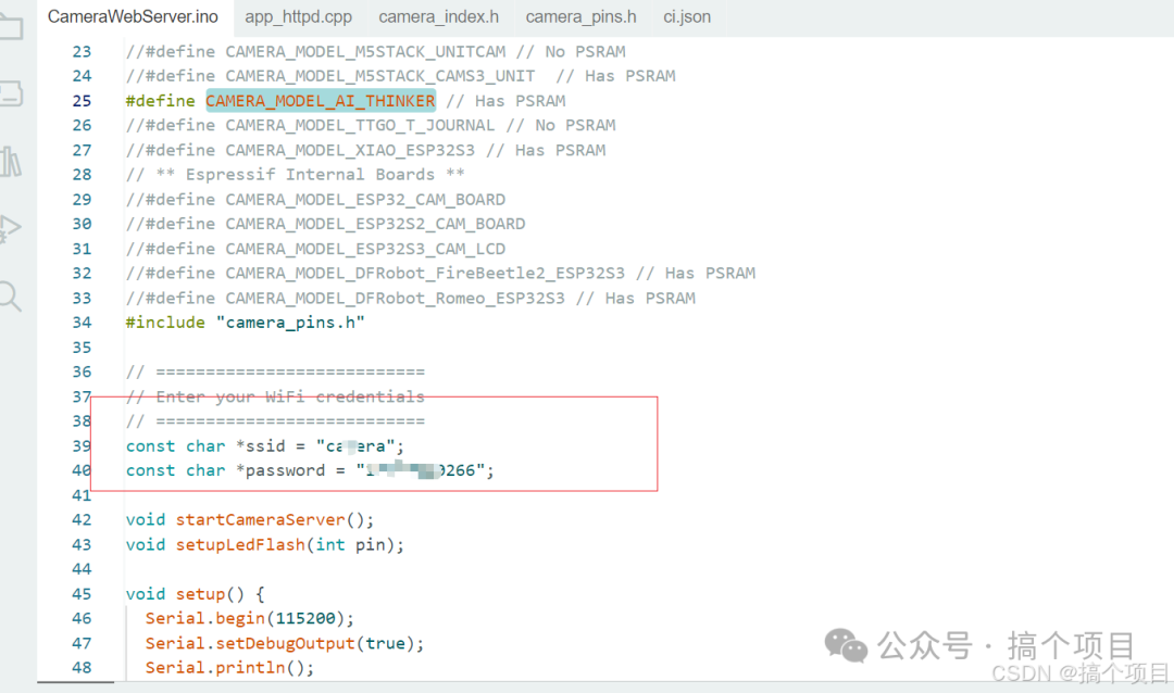
Enable the CAMERA_MODEL_AI_THINKER macro and disable other macros
 Edit
Edit
Configure the WiFi. This WiFi is for home use and needs to be connected to the same WiFi on the computer later.
 Edit
Edit
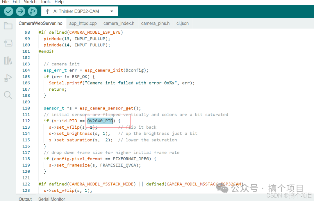
For the camera module selection: Here we choose the camera module OV2640, so we directly modify the code to OV2640_PID
 Edit
Edit
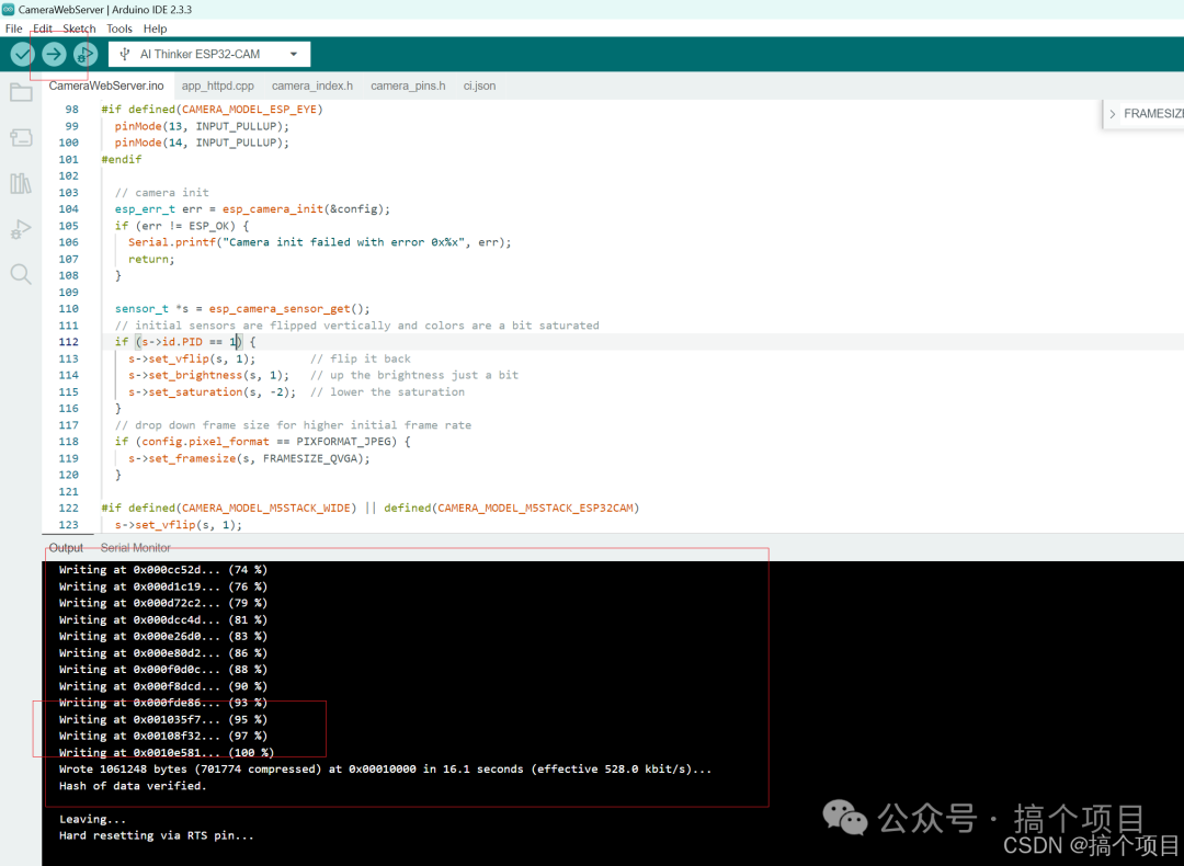
6. Code upload, after modifying the code, click Upload in the top left corner of the IDE. After the upload is complete, a Writing 100% prompt will appear.
 Edit
Edit
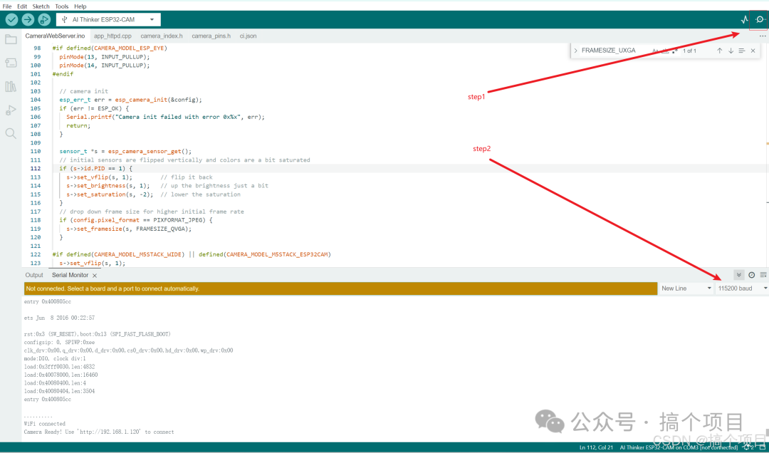
7. Click Serial Monitor to view the board’s information. After opening the serial information, click the lower right corner to adjust the baud rate to 115200, otherwise, the information displayed in the serial will be garbled.
 Edit
Edit
8. Check the corresponding IP in the serial display. Here my IP shows as http://192.168.1.120. This IP is the server address of the esp32-cam, and we will log in on the computer side.
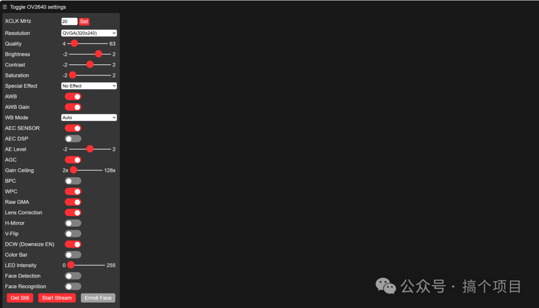
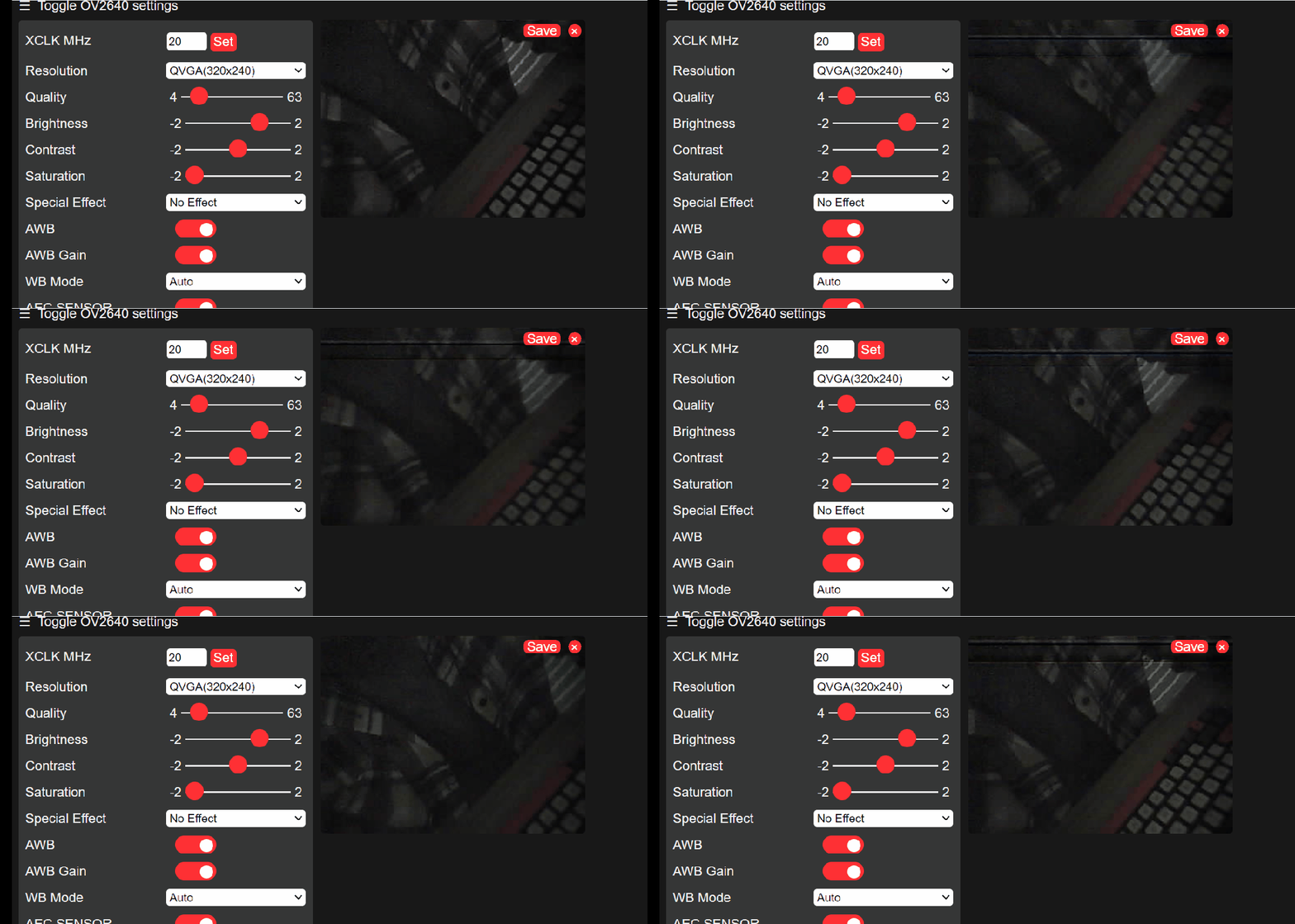
9. Here we select Start Stream to start viewing the video stream
 Edit
Edit