Zosi Automotive Research released the “2024 China Advanced Driver Assistance Redundant System Strategy Analysis Research Report“.
Framework for Defining Advanced Driver Assistance Redundant Systems
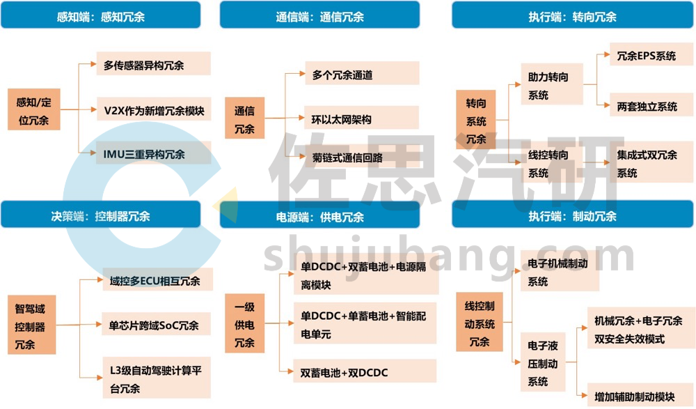
For autonomous vehicles, safety is the primary requirement. Advanced driver assistance must achieve complete redundancy to ensure true safety. Currently, most OEMs, Tier 1 suppliers, and Level 4 autonomous driving companies’ redundant designs mainly involve software and hardware backups:
-
Software level: Implement algorithm redundancy, for example, in GAC Group’s latest ADiGO PILOT intelligent driving system, using the AEB function algorithm, a strategy combining visual + millimeter-wave fusion algorithms with real-time redundancy verification of visual algorithms to maximize the reliability of AEB functions. -
Hardware level: This is reflected in different functional locations, such as perception, decision-making, execution, and power supply, all adopting dual or multiple redundancy designs to ensure that when one system fails, another system with the same function can operate normally.
Source: Zosi Automotive Research “2024 China Advanced Driver Assistance Redundant System Strategy Analysis Research Report”
Execution Redundancy: Full Redundant Design of Braking and Steering Systems
Execution redundancy and decision redundancy are the most critical parts, directly determining whether the vehicle can respond correctly at critical moments. Execution redundancy is usually placed in the braking and steering systems, designed to have two independent systems with the same function. Decision redundancy occurs in the brain, where the entire vehicle’s E/E architecture configures two core computing units, adopting a redundant architectural design concept from the vehicle architecture level, functional definition level, and system level.
-
The main products at this stage are electronic hydraulic braking systems (EHB), whose common redundancy scheme is a dual safety failure mode of mechanical redundancy + electronic redundancy and the addition of auxiliary braking module schemes; -
The trend towards brake system electrification is the future because electronic mechanical braking systems (EMB) completely abandon traditional braking fluids and hydraulic lines, generating braking force through motor drive, improving response speed, simplifying structural layout, and possessing inherent redundancy capabilities, but requiring extremely high reliability, making it difficult for large-scale production in the short term.
-
Currently, electric power steering systems (EPS) mainly use dual EPS steering redundancy schemes with two sets of motors, two power supplies, and two sets of windings, equivalent to two completely independent sets of EPS hardware, which are independent and back up each other, resulting in high overall costs; -
The steering system is evolving from electric power assistance to drive-by-wire. The drive-by-wire steering system (SBW) consists of three main parts: the steering wheel assembly, steering actuator assembly, and ECU, along with automatic fault prevention systems, power supplies, and other auxiliary systems, offering advantages such as fast response speed, flexible installation, lightweight, and high collision safety. Therefore, the drive-by-wire steering system requires redundancy backup for core components.
NIO NT 3.0 Platform Drive-by-Wire Steering System Redundant Design
-
Using a drive-by-wire steering system, the transmission and control of electrical signals between the steering wheel and steering wheel can be freely designed, with lower latency, more precise control, higher transmission efficiency, and more flexible layout; -
Implementing a full redundancy design with dual power supply, dual communication, dual hardware, and dual software, although there is no mechanical steering column connection between the steering wheel and steering wheel, compared to the commonly used electric power steering systems, its reliability has increased by 2.2 times; -
In December 2024, the first model of the NIO NT 3.0 platform, ET9, obtained the Ministry of Industry and Information Technology’s production license for drive-by-wire steering technology, becoming the first model in China equipped with drive-by-wire steering technology.
Source: NIO
Integrated Redundant Design for Central Computing Architecture
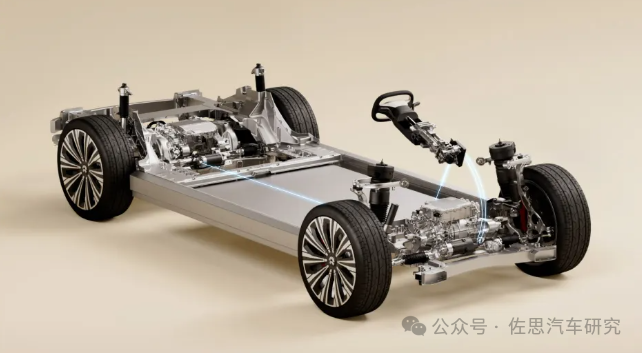
With the deepening application of intelligent connected and autonomous driving technologies, the vehicle’s braking and steering systems are evolving towards integration. Some OEMs and suppliers have launched central electronic and electrical architectures, and integrated chassis that combine braking, steering, and driving systems, adopting an integrated full redundancy design concept.
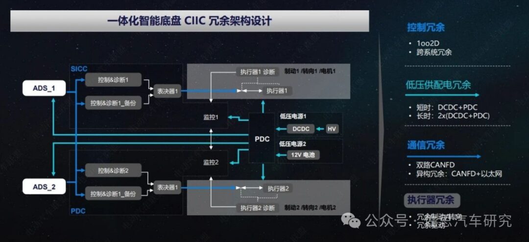
Times Intelligent CIIC Integrated Intelligent Chassis
-
CIIC integrates the vehicle’s driving system, braking system, steering system, and suspension system into the physical chassis, achieving platform design for software and hardware expansion; -
CIIC-M (medium platform) adopts full drive-by-wire technology, eliminating the mechanical connection between the brake pedal and the electronic control unit, achieving complete decoupling of the upper and lower vehicle bodies; at the same time, it adds software redundancy strategies, safety monitoring, and fault handling mechanisms to ensure system safety and robustness.
Source: Times Intelligent
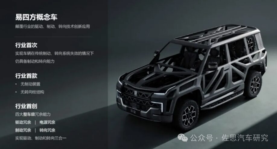
BYD Easy Four Square Platform
-
Equipped with four large motors of 220-240kW, through precise motor torque and speed control, combined with power-type blade batteries, new silicon carbide electronic control, and advanced thermal management technology, achieving a maximum braking deceleration of 1g; -
Using differential steering technology to steer, the left and right wheels obtain different torques, causing the wheels to deflect and complete the steering. The minimum turning diameter is 12 meters, and in an 18m serpentine pole test, the maximum passing speed is 60 km/h.
The Easy Four Square platform features a distributed drive format with four independently driven motors, ensuring basic driving capability even if only one motor operates. Additionally, the innovative technology of the Easy Four Square can provide dual redundancy backup for braking and steering based on existing braking and steering systems.
Source: BYD
Control Redundancy: Multi-ECU Redundancy is Still the Mainstream Solution, Future Development Towards Single-Chip Redundancy
The control system must meet the fail-operational requirements to implement L3 and above autonomous driving functions, meaning that after a sensor failure, the vehicle can still perform corresponding functions and safely complete its journey. To this end, the control system will apply two to three ECUs while embedding some redundant safety measures in certain sensors or achieving control redundancy through added chips in domain controllers.
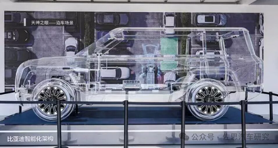
Multi-ECU Redundancy Scheme—BYD “Xuanji” Intelligent Architecture Dual Computing Platform
-
The “Tianxuan” cross-domain computing platform, as the main computing platform, integrates power domain, body domain, and chassis domain, adopting a multi-PCB design scheme to enable collaborative control of power domain, body domain, and chassis domain;
-
A backup computing platform “Tiandi” is added as a backup redundancy, connected to the front and rear control domains via gigabit dual Ethernet for emergencies.
Source: BYD
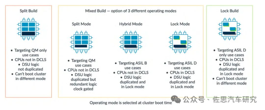
Single-Chip Redundancy Layout—Based on Renesas Multi-Domain Fusion SoC R-Car X5
Renesas Electronics recently launched the new generation of automotive multi-domain fusion SoC R-Car X5 (featuring ARM Cortex-A720AE core, meeting ASIL-B to ASIL-D functional safety requirements; 32-core design, CPU computing power up to 1000kDMIPS) supports safety isolation for multiple domains with different functional safety level requirements, utilizing hardware-based “fail-free interference (FFI)” technology. This hardware design achieves isolation of critical safety functions (such as drive-by-wire braking) from non-critical functions, allowing safety-related critical functions to be allocated to independent and redundant domains. Each domain has its own independent CPU core, memory, and interface, preventing potential catastrophic failures in the vehicle due to hardware or software failures in different domains.
Source: ARM
Table of Contents for the “2024 China Advanced Driver Assistance Redundant System Strategy Analysis Research Report”
Pages: 330 pages
01
Overview of Advanced Driver Assistance Redundant Systems
1.1 Definition of Advanced Driver Assistance Redundant Systems
Definition and source of advanced driver assistance redundant systems
Research structure of advanced driver assistance redundant systems (1)
Research structure of advanced driver assistance redundant systems (2)
Classification and types of advanced driver assistance redundant systems (1)
Classification and types of advanced driver assistance redundant systems (2)
1.2 Common Structural Designs for Advanced Driver Assistance Systems
Common redundancy architecture types for advanced driver assistance systems
Common redundancy architecture for advanced driver assistance systems—MooN voting structure (1)
Common redundancy architecture for advanced driver assistance systems—MooN voting structure (2)
Redundancy mode design for L3 autonomous driving system architecture
Redundancy design scheme for L3 autonomous driving system architecture—dual-system full autonomous driving system architecture
Redundancy design for L4 autonomous driving system architecture
02
Development Trends of Various Categories of Advanced Driver Assistance Redundant Systems
2.1 Perception Redundancy
Perception redundancy scheme one: Multi-sensor heterogeneous redundancy
Perception redundancy scheme one: Multi-sensor heterogeneous redundancy—fusion algorithms for multi-sensor information
Perception redundancy scheme one: Multi-sensor heterogeneous redundancy—multi-sensor fusion architecture types
Perception redundancy scheme one: Multi-sensor heterogeneous redundancy—multi-sensor fusion architecture (1)
Perception redundancy scheme one: Multi-sensor heterogeneous redundancy—multi-sensor fusion architecture (2)
Perception redundancy scheme two: V2X as a new redundancy module (1)
Perception redundancy scheme two: V2X as a new redundancy module (2)
Perception redundancy scheme three: IMU triple heterogeneous redundancy
Perception positioning redundancy case (1): Bosch perception module redundancy design
Perception positioning redundancy case (2): Mobileye’s True Redundancy sensor redundancy system (1)
Perception positioning redundancy case (2): Mobileye’s True Redundancy sensor redundancy system (2)
Perception positioning redundancy case (2): Mobileye’s True Redundancy sensor redundancy system autonomous driving solution
Perception positioning redundancy case (3): Bosch IMU positioning module redundancy design
Perception positioning redundancy case (4): Xinao threefold redundancy IMU
2.2 Decision (Control) Redundancy
Control redundancy scheme one: Domain control multi-ECU mutual redundancy (1)
Control redundancy scheme one: Domain control multi-ECU mutual redundancy (2)
Control redundancy scheme one: Domain control multi-ECU mutual redundancy (3)
Control redundancy scheme two: Single-chip cross-domain SoC redundancy strategy—Renesas R-Car X5
Control redundancy scheme two: Single-chip cross-domain SoC redundancy strategy—Qualcomm 8775
Control redundancy scheme two: Single-chip cross-domain SoC redundancy strategy—NVIDIA DRIVE Thor
Control redundancy scheme two: Single-chip cross-domain SoC redundancy strategy—Black Sesame Intelligence C1296
Control redundancy scheme three: L3 autonomous driving redundancy computing platform design (1)
Control redundancy scheme three: L3 autonomous driving redundancy computing platform design (2)
Domain control multi-ECU redundancy case (1)
Domain control multi-ECU redundancy case (2)
Domain control multi-ECU redundancy case (3)
2.3 Execution (Braking) Redundancy
Braking system technology route one: EHB (Electronic Hydraulic Drive-by-Wire System)
Braking system technology route one: EHB (Electronic Hydraulic Drive-by-Wire System) auxiliary components
EHB redundancy scheme one: Two-Box redundancy braking scheme, mechanical redundancy + electronic redundancy dual safety failure mode (1)
EHB redundancy scheme one: Two-Box redundancy braking scheme, mechanical redundancy + electronic redundancy dual safety failure mode (2)
EHB redundancy scheme one: One-Box redundancy braking scheme, adding RBU auxiliary braking module (1)
EHB redundancy scheme one: One-Box redundancy braking scheme, adding RBU auxiliary braking module (2)
EHB redundancy case (1): Huawei braking redundancy control system patent
EHB redundancy case (2): Jingwei Hengrun braking redundancy EWBS + ESP + EPB
EHB redundancy case (3): Nansen Technology Nbooster + ESC redundancy drive-by-wire braking system (1)
EHB redundancy case (3): Nansen Technology Nbooster + ESC redundancy drive-by-wire braking system (2)
EHB redundancy case (4): Bertli power supply redundancy and speed processing redundancy system
EHB redundancy case (4): Bertli electromechanical redundancy and hydraulic redundancy scheme
EHB redundancy case (5): Gelubo GIBS + ESC redundancy design (1)
EHB redundancy case (5): Gelubo GIBS + ESC redundancy design (2)
EHB redundancy case (5): Gelubo redundancy braking scheme’s demand for RBU
EHB redundancy case (5): Gelubo One-box vs. Two-box comparison
EHB redundancy case (5): Gelubo braking system development plan
EHB redundancy case (6): Likr Technology One-box braking system
EHB redundancy case (7): Yunkai Technology braking redundancy and control redundancy design
EHB redundancy case (8): Bosch execution module redundancy design (1)
EHB redundancy case (8): Bosch execution module redundancy design (2)
EHB redundancy case (8): Bosch execution module redundancy design (3)
EHB redundancy case (9): Continental Group MK Cx HAD redundancy drive-by-wire braking system (1)
EHB redundancy case (9): Continental Group MK Cx HAD redundancy drive-by-wire braking system (2)
EHB redundancy case (9): Continental Group KC1 vs. MKC2 comparison
EHB redundancy case (10): United Electronics vehicle motion domain controller VCU8.5 redundancy design (1)
EHB redundancy case (10): United Electronics vehicle motion domain controller VCU8.5 redundancy design (2)
Braking system technology route two: EMB (Electronic Mechanical Braking System)
Braking system technology route two: EMB (Electronic Mechanical Braking System)
Braking system technology route two: Some companies are laying out EMB products
EMB redundancy case (1): Tongyu Automotive EMB redundancy design
EMB redundancy case (2): Gelubo EMB redundancy scheme layout (1)
EMB redundancy case (2): Gelubo EMB redundancy scheme layout (2)
EMB redundancy case (2): Gelubo EMB redundancy scheme layout (3)
EMB redundancy case (3): Likr Technology EMB braking system
EMB redundancy case (4): Gelubo e-Pedal 2.0 redundancy design
EMB redundancy case (5): Times Intelligent integrated intelligent chassis drive-by-wire redundancy design
2.4 Execution (Steering) Redundancy
Steering system technology evolution route: Electric power steering drive-by-wire development (1)
Steering system technology evolution route: Electric power steering drive-by-wire development (2)
EPS redundancy scheme one: Mechanical system + TAS + electronic control composition redundancy EPS system
EPS redundancy scheme two: Two independent EPS redundancy systems
Redundant EPS key technology (1): Redundancy strategy and safety mechanism
Redundant EPS key technology (2): Advanced assistance algorithm architecture
Redundant EPS key technology (3): External request control function
EPS redundancy case (1): Jingwei Hengrun steering redundancy R-EPS
EPS redundancy case (2): Gelubo steering redundancy system
EPS redundancy case (2): Gelubo steering system development plan
EPS redundancy case (3): Deku Intelligent full redundancy intelligent steering solution (1)
EPS redundancy case (3): Deku Intelligent full redundancy intelligent steering solution (2)
EPS redundancy case (4): Yunkai Technology steering redundancy design
EPS redundancy case (5): Handing Intelligent Technology steering redundancy product (1)
EPS redundancy case (5): Handing Intelligent Technology steering redundancy product (2)
EPS redundancy case (6): Bosch execution module redundancy design (1)
EPS redundancy case (6): Bosch execution module redundancy design (2)
EPS redundancy case (7): Nansen steering system redundancy design
SBW redundancy scheme one: Dual redundancy system integrated design (1)
SBW redundancy scheme one: Dual redundancy system integrated design (2)
SBW redundancy scheme one: Dual redundancy system integrated design (3)
Redundant SBW key technology
SBW redundancy case (1): Hive steering high-safety drive-by-wire steering system
SBW redundancy case (1): Hive steering high-safety drive-by-wire steering system’s three redundancy design
SBW redundancy case (2): Handing Intelligent Technology SBW system redundancy design (1)
SBW redundancy case (2): Handing Intelligent Technology SBW system redundancy design (2)
2.5 Execution (Driving) Redundancy
Driving redundancy scheme: Two driving units mutually redundant
Driving redundancy case (1): Huawei multi-in-one electric drive system DriveONE redundancy design
Driving redundancy case (2): Full redundancy electronic control scheme based on dual three-phase brushless DC motors
Driving redundancy case (3): BYD Easy Four Square platform four motor independent driving mode
2.6 Power Supply Redundancy
Power supply redundancy scheme one: 12V dual-path redundancy power supply system (1)
Power supply redundancy scheme one: 12V dual-path redundancy power supply system (2)
Power supply redundancy scheme one: 12V dual-path redundancy power supply system, primary power supply scheme (1)
Power supply redundancy scheme one: 12V dual-path redundancy power supply system, primary power supply scheme (2)
Power supply redundancy scheme one: 12V dual-path redundancy power supply system, primary power supply scheme (3)
Power supply redundancy scheme one: 12V dual-path redundancy power supply system, secondary redundancy power supply (1)
Power supply redundancy scheme one: 12V dual-path redundancy power supply system, secondary redundancy power supply (2)
Power supply redundancy scheme one: Redundant design of high voltage + DCDC + 12V low voltage battery dual-channel power supply network (1)
Power supply redundancy scheme one: Redundant design of high voltage + DCDC + 12V low voltage battery dual-channel power supply network (2)
Power supply redundancy scheme two: 48V + 12V redundancy power supply network
Power supply redundancy scheme two: 48V can serve as a third voltage rail outside the 12V power supply and high voltage power supply
Power supply redundancy scheme two: L3 level autonomous driving power supply redundancy scheme (1)
Power supply redundancy scheme two: L3 level autonomous driving power supply redundancy scheme (2)
Power supply redundancy scheme (1): United Electronics regional controller power supply center redundancy design (1)
Power supply redundancy scheme (1): United Electronics regional controller power supply center redundancy design (2)
Power supply redundancy scheme (2): Aptiv power redundancy (1)
Power supply redundancy scheme (2): Aptiv power redundancy (2)
Power supply redundancy scheme (3): Jinmai Electronics dual-path redundancy power supply system design
2.7 Communication Redundancy
Communication redundancy scheme one: Setting multiple redundant channels between domains (1)
Communication redundancy scheme one: Setting multiple redundant channels between domains (2)
Communication redundancy scheme one: Setting multiple redundant channels between domains (3)
Communication redundancy scheme two: Building ring Ethernet architecture between domains
Communication redundancy scheme three: Tesla daisy chain communication loop
Communication redundancy case (1)
Communication redundancy case (2)
Communication redundancy case (3)
Communication redundancy case (4)
Communication redundancy case (5)
Communication redundancy case (6)
Communication redundancy case (7)
Communication redundancy case (8)
2.8 Comparison of Domestic and Foreign Supplier Redundant Systems
Summary of domestic and foreign supplier redundant systems (1)
Summary of domestic and foreign supplier redundant systems (2)
Summary of domestic and foreign supplier redundant systems (3)
Bosch autonomous driving system overall redundancy design scheme
Times Intelligent integrated intelligent chassis CIIC redundancy architecture design scheme
03
Analysis of OEM Advanced Driver Assistance Redundant System Strategies
3.1 Great Wall Motors
Great Wall Motors Coffee Intelligent Six Major Safety Redundant Systems
Great Wall Motors Coffee Intelligent Six Major Safety Redundant Systems Perception Redundancy: Multi-source heterogeneous sensor solutions
Great Wall Motors Coffee Intelligent Six Major Safety Redundant Systems Controller Redundancy, Architecture Redundancy
Great Wall Motors Coffee Intelligent Six Major Safety Redundant Systems Power Supply Redundancy, Braking Redundancy
Great Wall Motors Coffee Intelligent Six Major Safety Redundant Systems Steering Redundancy: Fully redundant steering system
Redundant systems equipped on Great Wall’s Mecha Dragon
3.2 Changan Automobile
Changan Automobile Advanced Driver Assistance Redundant System Design Scheme
Changan Automobile EPA1 E/E architecture decision redundancy design: Multi-chip redundancy
Changan Automobile EPA1 E/E architecture execution redundancy design: Dual redundancy braking system
Changan Automobile SDA E/E architecture perception redundancy design: Fusion perception system
Changan Automobile SDA E/E architecture communication redundancy design: ETH, CANFD dual redundancy channels
Changan Automobile SDA E/E architecture software and hardware redundancy design
3.3 GAC Group
GAC Group Advanced Driver Assistance Redundant System Design Scheme
GAC Group ADiGO PILOT intelligent driving system eight major redundancy systems
GAC Group ADiGO PILOT intelligent driving system perception redundancy: Multi-source heterogeneous sensor solutions
GAC Group ADiGO PILOT intelligent driving system perception redundancy: Urban NDA multi-sensor fusion perception scheme
GAC Group ADiGO PILOT intelligent driving system architecture redundancy, algorithm redundancy
GAC Group ADiGO PILOT intelligent driving system power supply redundancy: Dual power supply network
3.4 Dongfeng Motor
Dongfeng Motor Advanced Driver Assistance Redundant System Design Scheme
Dongfeng Motor integrated chassis system redundancy design
Dongfeng Motor integrated chassis drive-by-wire braking redundancy structure
Dongfeng Motor integrated chassis drive-by-wire components redundancy design (1)
Dongfeng Motor integrated chassis drive-by-wire components redundancy design (2)
Dongfeng Motor integrated chassis drive-by-wire software and hardware redundancy design (1)
Dongfeng Motor integrated chassis drive-by-wire software and hardware redundancy design (2)
3.5 BYD
BYD Advanced Driver Assistance Redundant System Design Scheme
BYD “Xuanji” E/E architecture decision redundancy design (1)
BYD “Xuanji” E/E architecture perception redundancy design (2)
BYD “Xuanji” E/E architecture communication redundancy design (3)
BYD e3.0 Evo platform power control system redundancy design
BYD Easy Four Square platform driving architecture redundancy design (1)
BYD Easy Four Square platform driving architecture redundancy design (2)
3.6 FAW Group
FAW Group Advanced Driver Assistance Redundant System Design Scheme
FAW Hongqi FEEA3.0 E/E architecture redundancy design (1)
FAW Hongqi FEEA3.0 E/E architecture redundancy design (2)
FAW Hongqi FEEA3.0 E/E architecture redundancy design (3)
FAW Hongqi FEEA3.0 E/E architecture power supply redundancy design: Dual power supply network
3.7 NIO
NIO NT3.0 platform and NT2.0 platform redundancy strategy comparison
NIO NT3.0 platform seven-fold safety redundancy design
NIO NT2.0 platform perception redundancy design: Aquila super sensor system + IMU + V2X multi-scheme verification perception
NIO perception redundancy scheme: Aquila super sensor system
NIO decision redundancy design: Central computing platform ADAM, adopting multi-ECU redundancy scheme (1)
NIO decision redundancy design: Central computing platform ADAM, adopting multi-ECU redundancy scheme (2)
NIO decision redundancy design: Central computing platform ADAM, adopting multi-ECU redundancy scheme (3)
NIO execution redundancy scheme: Chassis domain controller ICC redundancy design
NIO power supply redundancy design: Dual power supply layout (1)
NIO power supply redundancy design: Dual power supply layout (2)
NIO ET9 seven-fold safety redundancy design scheme
3.8 XPeng Motors
XPeng Motors Advanced Driver Assistance Redundant System Design Scheme
XPeng Motors XPILOT autonomous driving system redundancy design (1)
XPeng Motors XPILOT autonomous driving system redundancy design (2)
XPeng Motors X-EEA 3.0 architecture redundancy design
XPeng Motors X-EEA 3.5 architecture redundancy design (1)
XPeng Motors X-EEA 3.5 architecture redundancy design (2)
XPeng Motors X-EEA 3.5 architecture redundancy design (3)
XPeng Cang Hai platform redundancy design
XPeng Motors hardware redundancy system design (1)
XPeng Motors hardware redundancy system design (2)
3.9 Zhi Ji Motors
Zhi Ji Motors Advanced Driver Assistance Redundant System Design Scheme
Zhi Ji Motors decision redundancy: Central brain ZXD2 (cabin driving fusion) Horizon J6 + Qualcomm, multi-ECU redundancy scheme (1)
Zhi Ji Motors decision redundancy: Central brain ZXD2 (cabin driving fusion) Horizon J6 + Qualcomm, multi-ECU redundancy scheme (2)
Zhi Ji Motors all-domain motion control platform VMC redundancy design
Zhi Ji Motors IM AD system redundancy design
3.10 Leap Motor
Leap Motor Advanced Driver Assistance Redundant System Design Scheme
Leap Motor [Four-leaf Clover] integrated architecture redundancy design (1)
Leap Motor [Four-leaf Clover] integrated architecture redundancy design (2)
3.11 Nezha Motors
Nezha Motors Advanced Driver Assistance Redundant System Design Scheme
Nezha Motors “Shanhai 2.0” E/E architecture design (1)
Nezha Motors “Shanhai 2.0” E/E architecture design (2)
Nezha Motors Haozhi central supercomputing platform redundancy design
Nezha GT dual redundancy intelligent steering system design
3.12 Jidu Motors
Jidu Motors Advanced Driver Assistance Redundant System Design Scheme
Jidu Motors functional safety design of algorithm redundancy, perception redundancy
Jidu Motors functional safety design of perception redundancy, architecture redundancy
Jidu Motors functional safety design of controller redundancy
3.13 Jihe Motors
Jihe Motors Advanced Driver Assistance Redundant System Design Scheme
Jihe Motors IMC platform architecture design
3.14 BMW
BMW Advanced Driver Assistance Redundant System Design Scheme
BMW Personal Pilot L3 redundancy design of perception redundancy, chip redundancy
BMW Personal Pilot L3 redundancy design of architecture redundancy, system redundancy
BMW fail-operational driving system redundancy design
3.15 Volvo
Volvo Advanced Driver Assistance Redundant System Design Scheme
Volvo safety redundancy vehicle control system (1)
Volvo safety redundancy vehicle control system (2)
Volvo safety redundancy vehicle control system (3)
Volvo SPA2 architecture: Three computer clusters VCU + regional controller VIU
Volvo SPA 2 multi-domain hybrid architecture: System topology
Volvo autonomous driving truck redundancy safety technology
3.16 Tesla
Tesla Advanced Driver Assistance Redundant System Design Scheme
Tesla HW1.0—HW4.0 autonomous driving perception scheme iteration process
Tesla perception redundancy
Tesla chip redundancy—HW3.0 chip redundancy
Tesla chip redundancy—HW4.0 chip redundancy
Tesla braking redundancy
Tesla steering redundancy
Tesla computer redundancy, battery redundancy patents
Tesla VCFront’s power supply redundancy and isolation design
Tesla Cybertruck drive-by-wire steering system redundancy design
3.17 Mercedes-Benz
Mercedes-Benz Advanced Driver Assistance Redundant System Design Scheme
Mercedes-Benz DRIVE PILOT system redundancy design (1)
Mercedes-Benz DRIVE PILOT system redundancy design (2)
Mercedes-Benz STAR3 Domain dual 12V power supply architecture design
3.18 Comparison of Various Categories of OEM Redundant Systems
Summary of OEM perception redundancy systems (1)
Summary of OEM perception redundancy systems (2)
Summary of OEM perception redundancy systems (3)
Summary of OEM control redundancy systems (1)
Summary of OEM control redundancy systems (2)
Summary of OEM steering redundancy systems
Summary of OEM braking redundancy systems
Summary of OEM power supply redundancy systems
Summary of OEM communication redundancy systems (1)
Summary of OEM communication redundancy systems (2)
04
Analysis of L4 Autonomous Driving Company Advanced Driver Assistance Redundant System Strategies
L4 Autonomous Driving Company Redundant Systems Summary (1)
L4 Autonomous Driving Company Redundant Systems Summary (2)
4.1 Baidu Apollo
Baidu Advanced Driver Assistance Redundant System Design Scheme
Apollo autonomous vehicle redundancy design (1)
Apollo autonomous vehicle redundancy design (2)
Baidu Galaxy architecture platform
4.2 WeRide
WeRide Advanced Driver Assistance Redundant System Design Scheme
WeRide One
WeRide One redundancy system design (1)
WeRide One redundancy system design (2)
WeRide One redundancy system design (3)
4.3 Yuanrong Qixing
Yuanrong Qixing Advanced Driver Assistance Redundant System Design Scheme
Yuanrong Qixing perception redundancy design (1)
Yuanrong Qixing perception redundancy design (2)
Yuanrong Qixing perception redundancy design (3)
Yuanrong Qixing chip redundancy design
4.4 Yunji Zhixing
Yunji Zhixing Advanced Driver Assistance Redundant System Design Scheme
Yunji Zhixing high redundancy system design
Yunji Zhixing robot computing platform redundancy design
4.5 QCraft
QCraft Advanced Driver Assistance Redundant System Design Scheme
QCraft Driven-by-QCraft autonomous driving redundancy design (1)
QCraft Driven-by-QCraft autonomous driving redundancy design (2)
QCraft autonomous driving sensor kit redundancy design
4.6 Momenta
Momenta Advanced Driver Assistance Redundant System Design Scheme
Mpilot/MSD autonomous driving solution redundancy design (1)
Mpilot/MSD autonomous driving solution redundancy design (2)
Momenta provides the perception redundancy solution for Great Wall’s Mecha Dragon
Momenta 5.0 high-level intelligent driving system redundancy design
4.7 AutoX
AutoX Gen5 fifth-generation autonomous driving system redundancy design
AutoX full-stack redundancy design (1)
AutoX full-stack redundancy design (2)
4.8 Didi Autonomous Driving
Didi Twin Star platform multi-layer safety redundancy design (1)
Didi Twin Star platform multi-layer safety redundancy design (2)
Didi Autonomous Driving next-generation Robotaxi model redundancy design
4.9 Zhi Xing Zhe
Zhi Xing Zhe H-INP advanced driver assistance system redundancy design
Zhi Xing Zhe integrated intelligent driving system redundancy design
4.10 Waymo
Waymo Advanced Driver Assistance Redundant System Design Scheme
Waymo autonomous driving system redundancy design (1)
Waymo autonomous driving system redundancy design (2)
Waymo autonomous driving system redundancy design (3)
Waymo truck redundancy design (1)
Waymo truck redundancy design (2)
More Zosi Reports
Zosi 2025 Research Report Writing Plan
Intelligent Connected Vehicle Industry Chain Panorama (August 2024 Edition)
| Cloud and AI | ||
| Vehicle Cloud | OTA Research | Autonomous Driving Simulation |
| Automotive Cloud Service Research | Autonomous Driving Map | |
| TSP and Application Services | V2X and Vehicle-Road Collaboration | |
| Data Closed Loop Research | Roadside Intelligent Perception | |
| Vehicle-Road-Cloud Integration Research | ||
| AI Large Models | Automotive AI Large Model Research | Impact of AI Large Models on Vehicle Intelligence |
| Cockpit AI Agent | In-Vehicle AI Agent Product Development and Commercialization | |
| Smart Driving System Integration and Application Layer | ||
| Autonomous Driving Application Framework | ADAS and Autonomous Driving Tier 1 – Domestic | Self-owned Brand ADAS |
| ADAS and Autonomous Driving Tier 1 – Foreign | Foreign OEM ADAS Research | |
| L3/L4 Autonomous Driving and Startups | Ideal L8/L9 Function Disassembly | |
| Top 10 Intelligent Driving Tier 1 Comparison | ||
| Autonomous Driving Algorithms and Systems | End-to-End Intelligent Driving Research | Integrated Driving and Parking Research |
| Redundant Systems | Cabin Parking Integration | |
| Intelligent Driving Fusion Algorithms | Cabin Driving Parking Fusion | |
| Automotive Vision Algorithms | Unmanned Delivery Vehicle | |
| Navigation Assisted Driving (NOA) | ||
| Perception | Millimeter-Wave Radar | Automotive Vision |
| LiDAR Research | Infrared Night Vision | |
| LiDAR Core Components | Vehicle Ultrasonic Radar | |
| Software Defined Radar | In-Vehicle Cameras Tier 2 | |
| Intelligent Cabin System Integration and Application Layer | ||
| Intelligent Cabin Application Framework | Intelligent Cabin Tier 1 | Cabin Design Trends |
| Intelligent Cabin Platform | ||
| Cabin Display | In-Vehicle VR/AR/MR Research | HUD Industry Chain |
| Instrument and Central Control Display | Electronic Rearview Mirror | |
| Cabin Multi-Screen and Linked Screens | Driving Recorder | |
| HUD Industry Research | Intelligent Glass | |
| Cabin Interaction | In-Vehicle Voice | In-Vehicle Fragrance and Air Purification |
| In-Cabin Monitoring Research | Automotive Sound System | |
| Automotive Multi-Modal Interaction | Intelligent Surfaces | |
| Gesture Interaction Development | ||
| Cabin Interconnect Entertainment and Ecology | Automotive Ecological Domain | Self-owned Brand Vehicle Networking |
| Automotive Digital Key | Joint Venture Brand Vehicle Networking | |
| In-Vehicle Payment | New Force Brand Vehicle Networking | |
| In-Vehicle Information Entertainment | Commercial Vehicle Vehicle Networking | |
| Automotive eCall System | Commercial Vehicle Intelligent Cabin | |
| Other Cabin | Automotive Comfort System | Intelligent Door |
| Automotive Lighting | Shanghai Auto Show 75 Trends | |
| In-Vehicle Wireless Charging | Two-Wheeled Vehicle Intelligence | |
| OS and Supporting Layers | ||
| SDV Framework | Software Defined Vehicle | Automotive Software Business Model |
| Basic Software/System Platform | AUTOSAR Research | Automotive Operating System |
| Digital Instrument OS | ||
| Information Security/Functional Safety | Automotive Information Security | Automotive Functional Safety |
| Electronic and Electrical Architecture Layer | ||
| E/E Architecture Framework | E/E Architecture | Automotive Electronics OEM |
| 48V Low Voltage Power Supply Network | ||
| Intelligent Driving Domain | Autonomous Driving SoC | ADAS Domain Control Components |
| Autonomous Driving Domain Control | ||
| Cabin Domain | Intelligent Cabin Platform | Cabin Domain Control |
| Cabin SoC | 8295 Cabin Domain Controller Disassembly | |
| Vehicle Control Domain | Body (Region) Domain Control Research | Automotive VCU Research |
| Electric Drive and Power Domain Controllers | ||
| Communication/Network Domain | In-Vehicle Communication Chips | Commercial Vehicle T-Box |
| Wireless Communication Modules | High-Precision Positioning | |
| Automotive Gateway | In-Vehicle Antennas | |
| Passenger Car T-Box | Automotive UWB Research | |
| Cross-Domain Fusion | Multi-Domain Computing and Regional Controllers | |
| Regional and Central Computing | Body (Region) Domain Control Research | |
| Other Chips | Automotive MCU Research | Vehicle RISC-V Research |
| In-Vehicle Storage Chips | Sensor Chips | |
| Power Management Chips | Automotive CIS Research | |
| Power Layer | ||
| Power | Hybrid Power Report | Power Management Chips |
| 800V High Voltage Platform | Electric Drive and Power Domain Research | |
| IGBT and SiC Research | ||
| Energy | Integrated Battery | Charging and Discharging Research |
| Fuel Cells | Mobile Charging Robots | |
| Solid-State Batteries | Digital Power and Chips | |
| Others | Thermal Management Systems | Integrated Die Casting |
| Mechanical Layer | ||
| Chassis/Execution | Passenger Car Chassis Domain Control | Electronic Control Suspension |
| Drive-by-Wire & AEB | Key Components of Intelligent Steering | |
| Steering System | Commercial Vehicle Intelligent Chassis | |
| Other Macros | ||
| Model Platform | OEM Modular Platform | OEM Model Planning Research |
| Going Global | OEM Overseas Layout | |
| Policies, Standards, and Access | Intelligent Driving Regulations and Vehicle Globalization | Autonomous Driving Standards and Certification |
| AI Robots | PBV and Automotive Robots | Unmanned Delivery Vehicles |
| Mobile Charging Robots | Flying Cars |
「Zosi Research Monthly Report」

「Contact Information」
Mobile number same as WeChat number

Industry Research Department丨 Mr. Fu 15810027571
Mr. Zhao 18702148304
Data Service Department丨 Ms. Zhang 13716037793
Strategic Consulting Department丨 Ms. Han 15810133447
Promotion and Communication Department| Ms. Liao 13718845418