This is a very practical share that not only introduces the project’s functions but also provides reasons for doing so. At the end, it offers learning suggestions for everyone.
01 Project Introduction
The prototype of this project was my undergraduate graduation project, built from scratch, including hardware schematics, PCB, component soldering, lower machine programming, upper machine programming, ZigBee wireless communication programming, and testing and modifying issues across various modules.
The project is actually quite simple; the lower machine collects data from various sensors. After collecting this data, it will be summarized and packaged, then sent through the serial port to the ZigBee terminal node. The terminal node sends it to the ‘coordinator’, which then sends the data to the upper machine via the serial port. The upper machine verifies and unpacks the data and distributes it to various pages for display based on different data types.
The upper machine platform uses an ARM development board, which is essentially a more powerful single-chip computer with a screen that supports touch interaction. The upper machine program is written in C/C++/Qt.
Below is the entire project interaction relationship diagram:
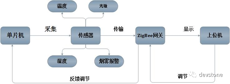
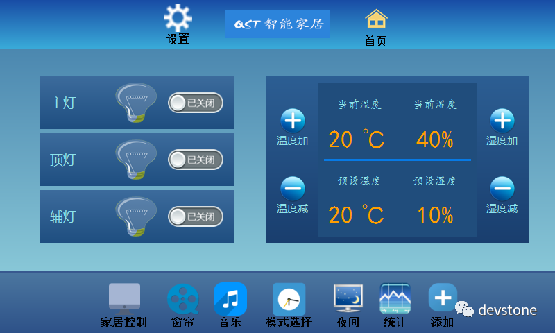
Monitoring is bidirectional; data is sent from the sensors to the upper machine, and the upper machine can also issue corresponding commands through control buttons, such as turning the LED light on and off, controlling sensor thresholds, for instance, if the comfortable indoor temperature is 22°, when the sensor detects a value exceeding this, it triggers an alarm for notification.
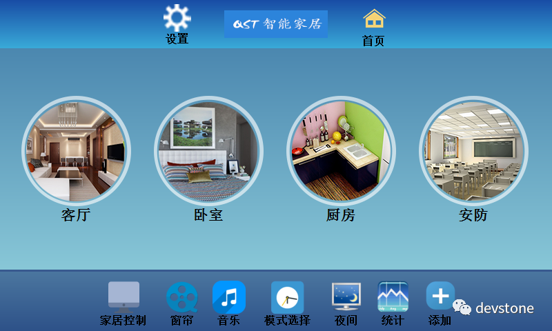
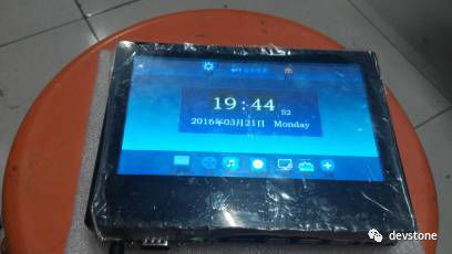
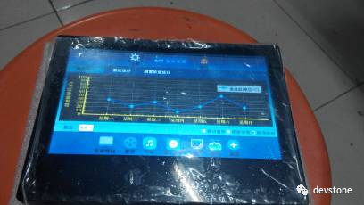
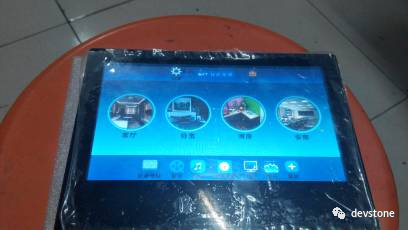
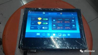
Below are some screenshots of the upper machine program interface:
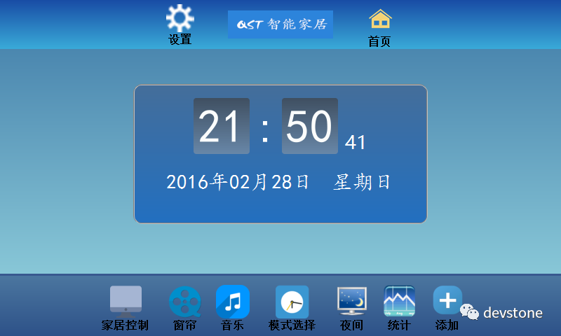
The screenshots were taken during the demonstration back then. It has been many years since, and I fondly remember the entire production process.
At this point, many might be confused as to why so many ZigBee nodes and STM32 were used; using only ZigBee would have sufficed. Indeed, collecting sensor data is not labor-intensive, and using CC2530 would have been enough. I did this to apply all the knowledge I had learned.Detailed explanations will be divided into several parts below.
02 Upper Machine Introduction
To cater to newcomers, let me briefly explain what an upper machine is.
An upper machine is a computer that can issue control commands. In layman’s terms, it is a software running on a platform (Windows, Linux, macOS, etc.) that allows you to perform a series of operations.
The original design had the upper machine running on an ARM platform, which is essentially a board; you can think of it as a tablet computer.
So someone might ask, can it run on other platforms? Of course, you can compile and run it directly on Windows, Linux, or macOS. Currently, there are no restrictions in the code.
Now everyone should understand, I believe that after seeing the not-so-great images above, you should have a general idea about the upper machine.
If you download my upper machine code and find errors during compilation, feel free to leave a message, and I’ll add more details. Normally, it should compile and run without errors now.
03 Lower Machine Introduction
Once you understand the upper machine, understanding the ‘lower machine’ should be much easier.
The lower machine is a type of computer that controls device states. In simple terms, you can think of it as writing programs to control a microcontroller to perform a series of operations, such as lighting an LED, etc. These series of program codes can be understood as the lower machine program.
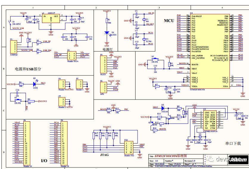
The lower machine uses the STM32F103 VBT66 microcontroller, which is an ARM® Cortex®-M3 version with only 128KB of ROM size, and the control program runs entirely on this microcontroller.
I remember back then, to show off, I also ported a micro-operating system UCOSII (Micro-Controller Operating Systems). This is a real-time operating system entirely written in C language, based on a preemptive priority strategy multi-tasking system, which means we can run multiple tasks simultaneously.
After porting this operating system, the remaining program writing became very simple; collecting data from multiple sensors can be treated as different tasks. You can worry about how to poll them.
STM32 plays the role of data collection + packaging relay here. Some sensor data, after collection, is encapsulated into a package and sent via the serial port, the other end of which is connected to the ZigBee terminal. The terminal receives the data and sends it to the ZigBee coordinator via the ZigBee wireless communication protocol.
The ZigBee coordinator is connected to the ‘upper machine’, allowing the upper machine to receive the data.
04 ZigBee Wireless Communication Introduction
ZigBee is a short-range wireless communication protocol that uses the IEEE 802.15.4 standard at the bottom layer. Its main features include: low power consumption, low cost, low speed, and support for a large number of nodes to send and receive data.
The communication hardware uses the CC2530 chip, and wireless communication can be roughly divided into three types: nodes, routers, and coordinators.
In this project, I took a shortcut and did not strictly follow the above model. In my project, ZigBee only serves the purpose of data transmission, meaning the collected data is sent from the ‘terminal node’ to the ‘coordinator’. In practical applications, it would not be such a waste, as coordinators not only handle data transmission but can also take on part of the data collection management tasks.
In the open-source code I shared, the zigbee wireless transmission part contains all the ZigBee communication code, including the terminal nodes and the coordinator. Just be sure to distinguish when downloading the program.
“
As for how to download and debug, please search it yourself on Baidu.
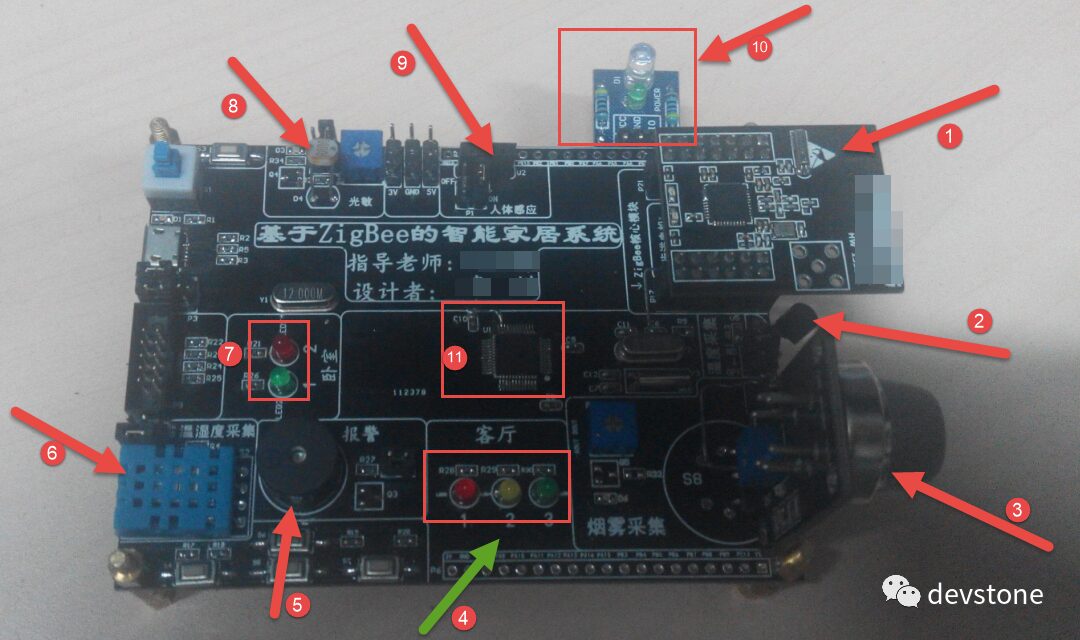
05 Hardware PCB Circuit Introduction
I believe everyone has seen the appearance of the board; it is very simple and lacks any aesthetics, purely designed to accomplish functionality.

Friends who have studied hardware design can skip this part as it is too basic. If you are interested in this area, you need to systematically learn some basic knowledge; it’s quite quick to learn, just like building with blocks.
How does a circuit board come about?
First, you need to use software to draw the schematic diagram and understand some basic circuit knowledge. However, there are many ready-made resources available online that you can reference.
Next, generate the PCB based on the schematic. This step is crucial; after generating it, you need to manually route or connect it. This step is quite tedious and important; many beginners tend to take shortcuts and choose automatic routing, but I strongly advise against this. It is better to choose manual routing.
What is routing? In layman’s terms, it means connecting the pins of various components using specific lines. You need to reconnect how a certain component in your schematic connects to the outside world. The principle is to keep each line evenly spaced, not overlapping, and not winding unnecessarily.
Finally, once the PCB is drawn, you can export it and send it to the manufacturer for ‘prototyping’. It is getting cheaper and cheaper now; you can directly search for reputable vendors on Taobao. Just make sure to communicate clearly with the seller about the requirements for the board you want to prototype, such as whether to cover the vias with oil, ink color, via size, etc.
Generally, the prototyping can be completed in about a week, and the remaining time is for you to buy components for soldering. This step is also quite tiring and laborious; be careful not to buy the wrong size, as it needs to match the sizes you used when drawing the schematic, such as 0603, 0204 packages, etc.
Lastly, test whether the circuit board has any issues. Actually, when you start soldering, you can first solder part of the circuit for testing. If there are no issues, then solder the rest.
Conclusion
Above is the explanation of several major parts of this project. For detailed knowledge, you can refer to my previous blog and the open-source code materials.
The overall idea is that the microcontroller collects sensor data and sends it to the upper machine for display via wireless communication, while the upper machine can also control hardware facilities in the lower machine, such as lighting LED lights. Of course, here the LED light simulates the actual lighting in the environment; if it is to be used in a real environment, corresponding driver circuits would be required.
If you still have questions after reading this, let’s continue the discussion. I will compile everyone’s doubts and publish them to help more beginners learn and understand.
If this small project can help you, please give it a thumbs up or a view; it is a form of support for me.
About Learning
Finally, I would like to give some personal suggestions to beginners about how to learn:
Have you noticed how important learning ability is after entering society? Perhaps you didn’t pay attention to it when you were in school, where the teacher guided you through the learning process, and you only needed to follow along.
However, after graduating and working, you find that no one is there to guide or teach you; you have to learn, research, and delve into everything by yourself. Many things are hard to learn and understand.
As a technical person, it is quite harsh; technology changes rapidly. If you stop learning, you might not see immediate changes, but as time goes on, you will feel increasingly out of step compared to others. This gap is not only reflected in abilities but also directly in salary levels. So, will you learn?
-
Learn to Use Search Engines
For various problems we encounter, over 99% have solutions online, so knowing how to search correctly is crucial. I strongly recommend that everyone use Google for searches when possible instead of Baidu.
-
Share More Summaries
We must believe in a saying: ‘Altruism is self-benefit.’ By sharing and contributing more, we may not receive immediate returns, but in the long run, these contributions will pay off exponentially.
-
Learn to Ask Questions
Asking questions is an art that many people overlook. Many experts are busy, so when we seek help, we should try to describe our problems clearly in one go, for example, using the following template:
I want to implement the xx function but encountered the xxx problem. This is what I think… After trying the xxx steps, I still couldn’t solve it. Could you please take some time to help me?
Casual Talk
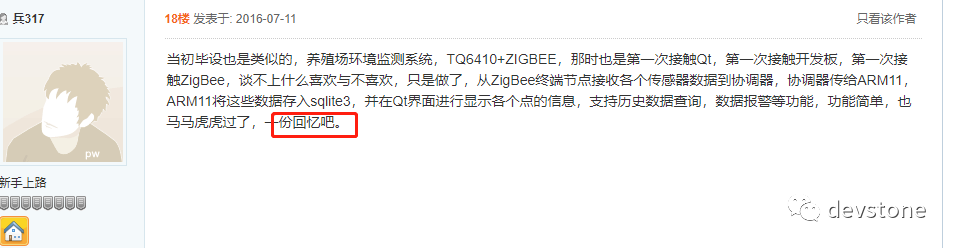
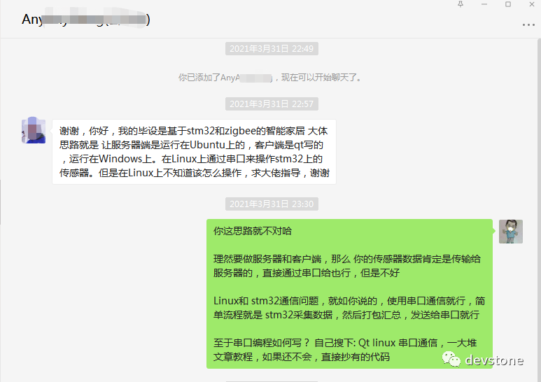
This small project, shared by chance, has unexpectedly received a lot of appreciation from friends, and I am very happy to help everyone. In fact, many people ask very basic questions, and as someone who has been through this, I know that there are many doubts and questions when just starting out. Whenever I have time, I reply to each one.
Below are some feedback from friends:
Finally, if anyone has questions, you can follow my public account and ask me anything anytime. However, please try to describe your questions clearly in one go. Don’t ask if I’m available, if I can ask you a question, if you’re busy, etc. Just ask your question directly, it’s that straightforward.
I am quite busy with work as well, so I may not respond immediately, but I will definitely reply to you as soon as I can.

Graduation Design Series:
Temperature/Heart Rate/Step Count Design Based on STM32
Smart Automatic Light-Seeking Fire Extinguishing Car
51 Microcontroller + HX711 to Achieve Simple Electronic Scale
Low-Cost STM32 IoT Portable Power Meter
STM32 + OV7670 Design License Plate Recognition System
Homemade Mobile App and Arduino to Achieve Smart Monitoring Control System
STM32F103 + NB Module + MQTT to Achieve IoT Collection System
7-Day Completion of Gesture-Controlled ESP32 WiFi Electronic Photo Album
Homemade STM32 Multimeter, Outperforming 500 Yuan Regular Brands
Homemade Simple Blood Oxygen Heart Rate Monitor STM32 + MAX30100
STM32 + Zigbee Network Ordering System
STM32 Smart Trash Can Automatically Identifying Various Wastes
Parking Assistant Based on MCU Development Board + Camera
Body-Sensing Gimbal Design Based on STM32 and MPU6050
A Smarter ‘Xiao Ai’?
STM32F4 + H7 to Achieve Bionic Robot Dog
Low-Cost 360° Monitoring System
STM32 Version RFID Medical Order Special Bracelet
Smart Home System Design Controlled by STM32 Microcontroller
STM32F4 E-Reader Production Tutorial
Graduation Design | Smart Infusion Monitoring System
Raspberry Pi 3B+ and OpenCV3 + PyQt5 Achieve Face Recognition Access Control
Gesture-Controlled Dot Matrix Display Design Based on STM32
Immediate Learning and Sharing the Complete Process of Building a Fingerprint Recognition System
Homemade Hexapod Robot, Challenging, Enter at Your Own Risk
True Human-Machine Interaction, Cloud Smart Butler (My Graduation Project, My Heart and Soul)
STM32 Bluetooth Smart Car (Sharing Code and Android APK)
STM32 + TI BQ76940 Design 48V BMS Plan (Data Sharing)
STM32 Slope Driving Line Following Car Production Tutorial
Simple Fatigue Driving Detection Under 100 Yuan
STM32 + OneNET to Achieve NB-IOT Power Collection System
Designing a Parking Lot Management System on ARM Platform (Includes Tutorial & Data)
Smart WiFi LED Light Design
LCD Digital BOOST Circuit Design
STM32 Smart Baby Crib Monitoring (Basic Version)
STM32 + UART HMI, Playing Minesweeper Game
Two-Wheeled Self-Balancing Car, Including Source Code, Schematic/PCB Source Files
STM32 Logistics Handling Car
STM32F407 Smart Car: Most Comprehensive Functions Online, Open Source Code
Microcontroller Automatic Sorting Car (Loading/Unloading/WIFI Recognition)
Self-Balancing Robot on a Ball
Project Sharing | Electronic Competition Series | Artificial Intelligence | Postgraduate Entrance Examination
Must-Know Knowledge Points | Graduation Design | Switch Power Supply | Job Hunting
We are Nimo, the founder of Darwin, a Miss who only talks about technology and not flirting. DarwinDarwin Online Education Platform aims to serve professionals in the electronics industry, providing skill training videos covering popular topics in various subfields, such as embedded systems, FPGA, artificial intelligence, etc., and tailoring layered learning content for different groups, such as commonly used knowledge points, disassembly assessments, electronic competitions/intelligent cars/postgraduate entrance examinations, etc. Welcome to follow.