1
The Origin of Serial Ports
The serial port emerged around 1980, with data transmission rates ranging from 115kbps to 230kbps. Initially, the serial port was designed to connect computer peripherals, such as mice, external modems, old cameras, and graphics tablets. It can also be used for interconnecting two computers (or devices) for data transmission.
Due to the lack of hot-swapping support and relatively low transmission rates, some new motherboards and most portable computers have begun to eliminate this interface. Serial ports are primarily used in industrial control, measurement equipment, and some communication devices.
1
Definition
A serial interface, abbreviated as serial port, refers to the sequential transmission of data bit by bit. Its characteristic is that the communication line is simple; only a pair of transmission lines is needed to achieve two-way communication (telephone lines can be used as transmission lines), significantly reducing costs, especially suitable for long-distance communication, but the transmission speed is relatively slow.
The communication method where each bit of information is transmitted sequentially is called serial communication. The features of serial communication include: data bits are transmitted in order, and it requires at least one transmission line; it is cost-effective but has a slow transmission speed. The distance of serial communication can range from a few meters to several kilometers; depending on the direction of information transmission, serial communication can be further divided into simplex, half-duplex, and full-duplex.
1
Basic Principles
Any communication requires a medium for information transmission, whether wired or wireless. Serial communication is wired communication through serial lines, requiring at least two lines (GND and signal line) for simplex communication. A GPS module is a typical example of serial simplex communication. Furthermore, most serial communication uses three lines (TXD, RXD, GND) to achieve full-duplex communication.
Serial communication is asynchronous; thus, both parties must agree on communication parameters in advance. These parameters include baud rate, data bits, parity bits, stop bits, and hardware flow control. Any incorrect setting of these parameters can lead to communication failure. For instance, if the baud rate is set incorrectly, the sender may send correctly, and the receiver may receive, but all received data will be garbled.
Advantages and Disadvantages of RS232, TTL, RS422, and RS485
Intelligent wireless
1. RS-232
Intelligent wireless
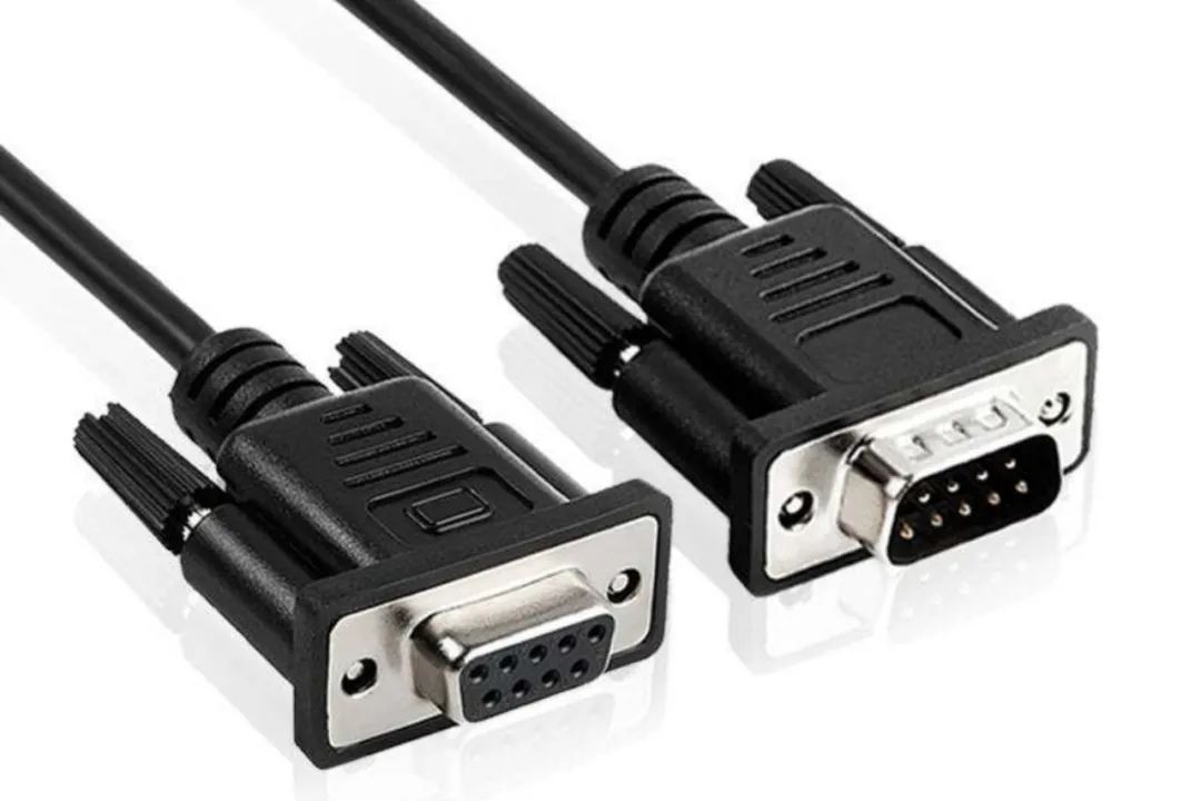
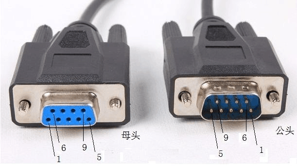
The RS-232 interface conforms to the serial data communication interface standards set by the Electronic Industries Alliance (EIA) and is widely used for connecting computer serial interface peripherals, such as some older PCs equipped with RS232 interfaces. The RS232 operates in a single-ended mode, which is an unbalanced transmission method. The logic levels of the signals at the sender and receiver are relative to the signal ground. RS232 was initially designed for one-to-one communication between DTE (Data Terminal Equipment) and DCE (Data Communication Equipment), typically used for full-duplex transmission but can also be used for half-duplex transmission.
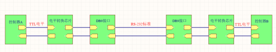
Advantages and Disadvantages
The communication data line consists of 2 lines (RX, TX), supporting full-duplex communication.
The signal level of the interface is relatively high, which can easily damage the circuit chips. Additionally, due to its incompatibility with TTL levels, a level conversion circuit is required to connect with TTL circuits.
The transmission rate is relatively low; during asynchronous transmission, the baud rate is 20Kbps. Therefore, in CPLD development boards, the integrated program baud rate can only be set to 19200, which is the reason for this limitation.
The interface uses one signal line and one signal return line, forming a common-ground transmission method. This common-ground transmission is prone to common-mode interference, resulting in weak noise immunity.
The maximum transmission distance is limited, with a standard maximum transmission distance of 50 feet, but in practice, it can only be used within about 15 meters.
2. RS485
Intelligent wireless
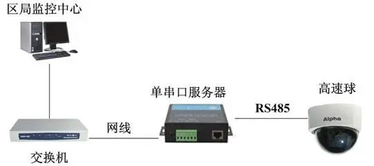
To expand the application range, the EIA established the RS-485 standard in 1983 based on RS-422. The RS485 bus transmission protocol is a standard for serial bus communication, employing a balanced transmission and differential reception structure. RS485 is not a point-to-point bus structure but a distributed architecture that can connect up to 128 transceivers.
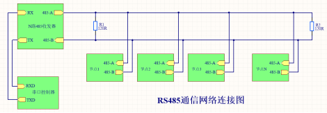
Advantages and Disadvantages
RS-485 employs balanced transmission and differential reception, thus possessing the ability to suppress common-mode interference.
Its maximum transmission distance is 1200 meters, practically reaching 3000 meters, with a maximum transmission rate of 10Mbit/s. Therefore, RS-485 serial communication is widely used when the communication distance ranges from several meters to thousands of meters.
Communication data can use two-wire and four-wire configurations; two-wire only supports half-duplex, while four-wire functions similarly to RS422.
Due to electrical characteristics, two-wire configurations allow for multi-point bidirectional communication, with a maximum of 32 devices connected.
The RS485 bus is a conventional communication bus that cannot perform bus arbitration, meaning it cannot send data simultaneously to avoid bus contention. Consequently, the overall communication efficiency of the system is lower, with a significant amount of data redundancy, making it unsuitable for applications requiring high speed. Additionally, since usually only one host is on the RS485 bus, this bus method is a typical centralized-distributed control system. If the host fails, the entire system’s communication will be paralyzed; therefore, having an online backup for the host is an important measure.
3. RS-422
Intelligent wireless
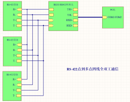
RS-422 is a series of specifications using 4 wires for full-duplex, differential transmission, and multi-point communication protocols. It employs balanced transmission with unidirectional/non-reversible transmission lines, with or without enable lines. Unlike RS-485, RS-422 does not allow multiple transmitters but can have multiple receivers. In hardware composition, RS-422 is equivalent to two sets of RS-485, where two half-duplex RS-485 form a full-duplex RS-422.
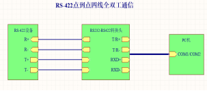
Advantages and Disadvantages
Communication data uses a 4-wire configuration (TX+, TX-, RX+, RX-), employing separate sending and receiving channels, supporting full-duplex.
The maximum transmission distance is 4000 feet (approximately 1219 meters), with a maximum transmission rate of 10Mb/s; for communications within 300 meters, terminal resistors are not needed, while for distances over 300 meters, 120-ohm terminal resistors are required.
Due to electrical characteristics, it only allows point-to-multipoint bidirectional communication, with a maximum of 10 nodes (1 master, 9 slaves), and slaves cannot communicate with each other.
4. TTL
Intelligent wireless
The TTL interface belongs to parallel data transmission interfaces. When using this interface, it is unnecessary to use dedicated interface circuits between the LCD driver board and the LCD panel; instead, the TTL data signals output by the driver board’s main control chip are directly transmitted to the LCD panel’s input interface via cable.
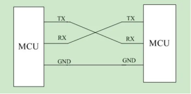
TTL is used for communication between two MCUs.
Advantages and Disadvantages
Due to high signal voltage, many connections, and long transmission cables, the circuit’s anti-interference capability is relatively weak, and it is prone to electromagnetic interference (EMI).
TTL transmits at a fixed rate but can transmit multiple bits simultaneously.
Analysis of RS232, TTL, RS422, and RS485
Intelligent wireless
1
Operating Modes
RS232 and TTL operate in full-duplex mode. RS232 uses two different signal lines with a common ground for transmission, where each signal line has a transmitter and receiver at both ends, allowing simultaneous data transmission and reception in two different directions. This mode is convenient for devices with perfect time control, such as remote monitoring equipment.
RS422 operates in full-duplex mode. RS422 uses four signal lines, i.e., two pairs of twisted wires for data transmission, with two lines for data transmission and the other two for data reception, with transmitters and receivers at both ends of the four wires. This mode is also used for remote monitoring devices requiring high efficiency and precision.
RS485 can operate in both full-duplex and half-duplex modes, but it is most commonly used in half-duplex mode. RS485 uses two signal lines for data transmission, which cannot transmit and receive data simultaneously. Only after the data transmission is complete can the receiving action occur. Although both RS232 and RS485 use two lines, RS485 transmits in the same direction.
2
Network Topology
RS232 and RS422 both use point-to-point communication, which means single-station capability, where one host communicates with one slave and cannot connect to a network.
RS485 uses point-to-multipoint communication, allowing one host to communicate with multiple slaves, with the number of slaves reaching up to 128. The multi-station capability of RS485 can establish a network between devices more quickly.
3
Transmission Method
RS232 uses single-ended transmission, where the transmitter and receiver are relatively fixed, and one port can only transmit signals while the other can only receive signals; only the ground of the two lines needs to be connected. The advantage of single-ended transmission is that wiring is relatively easy and cost-effective. However, the drawback is that the ground potential of the two connected points may differ, potentially affecting the quality of signal transmission.
TTL uses single-ended transmission.
RS422 and RS485 use balanced sending and differential transmission methods, where the transmitter and receiver are not fixed, and both ports transmit signals. The quality of the signal can be determined by the voltage difference during signal transmission. The advantage of single-ended transmission is that the difference in ground potential is reflected in the signal fluctuations at both ports, but the voltage difference does not change significantly. Additionally, during differential transmission, both ports generate induced electromotive force, which cancels each other out, providing better anti-interference and driving force. The drawback is that wiring is more complicated.
4
Electrical Interfaces
The RS232 interface standard uses negative logic. That is, when the logic is “1,” the level difference is between -15V and -5V, and when the logic is “0,” the level difference is between 5V and 15V.
TTL devices output low levels below 0.8V and high levels above 2.4V. For inputs, below 1.2V is considered 0, and above 2.0 is considered 1. Thus, the noise tolerance for TTL low-level input is only (0.8-0)/2=0.4V, while the noise tolerance for high-level input is (5-2.4)/2=1.3V.
The interface standards for RS422 and RS485 are both positive logic, meaning that when the logic is “1,” the level difference is between 2V and 6V, and when the logic is “0,” the level difference is between -6V and -2V. The level difference for positive logic is much lower than that for negative logic, reducing the risk of circuit damage and allowing compatibility with TTL levels.
5
Transmission Rates
RS232 has a relatively low transmission rate, with a maximum baud rate of 115.2Kbps and a theoretical transmission distance of 50 meters, while the actual transmission distance is about 15 meters.
RS422 and RS485 have higher transmission efficiency, with a maximum baud rate of 10Mbps, a theoretical transmission distance of 4000 meters, and an actual transmission distance of 3000 meters. Even at a low baud rate of 19Kbps, it can transmit up to 1200 meters.
TTL has a transmission distance of 2 meters, but it is generally stated as 15 meters; lowering the baud rate can extend this distance, which is related to the electromagnetic environment. This is mainly limited by the load capacity and anti-interference capability of TTL devices.
6
Terminal Resistors
For RS422 interfaces, to prevent signal reflections from interfering with the signal, a terminal resistor must be installed at the end of the transmission line.
For RS485 interfaces, to prevent signal reflections from interfering with the signal, two terminal resistors must be installed at each end of the transmission bus.
For RS232 interfaces, terminal resistors are not required.
Thus, the RS485 interface has a more complete setup and stronger environmental adaptability, but its operational costs are higher than those of RS232 and RS422 interfaces.
END