Previously, I explained the power-on and startup control strategies for the EDC7 and EDC17 computer boards. If you haven’t seen it, you can click below to review.
↓↓↓↓↓↓
Detailed Explanation of Power-On Control Strategies for Various ECUs (Part 1)
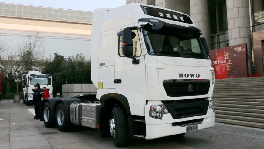
Today, I will explain another control strategy for startup using CAN communication signals. The heavy-duty truck T7H is equipped with a MAN engine and has a blue MINI controller as its body computer.
The computer board used for the MAN engine is also the Bosch EDC17CV44. Let’s look at how it differs from others:
01
The Computer Board and MINI Both Require Power and Grounding
The engine ECU’s power supply has three grounding wires connected to pins 2, 4, and 6 of the ECU K connector, and the three power wires of the engine ECU are connected to pins 1, 3, and 5 of the K connector, just as we learned before;
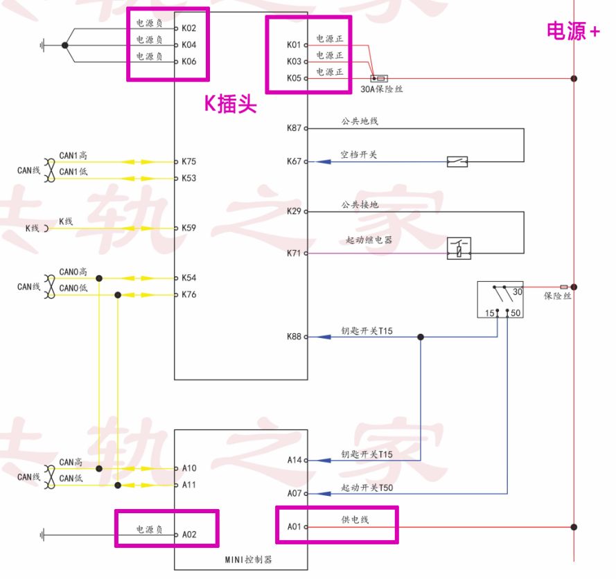
However, the additional body controller MINI also requires power and grounding, with the power coming from pin A1 of the MINI and grounding from pin A2.

02
Power-On Activation of the Computer Board and MINI
The power-on activation of the engine ECU is triggered by pin K88 of the K connector. When the ignition switch is ON, pin 88 of the K connector receives the power signal from the ignition switch, successfully activating the ECU computer board and entering standby startup mode. (Battery → Ignition Switch → ECU K Connector Pin 88).
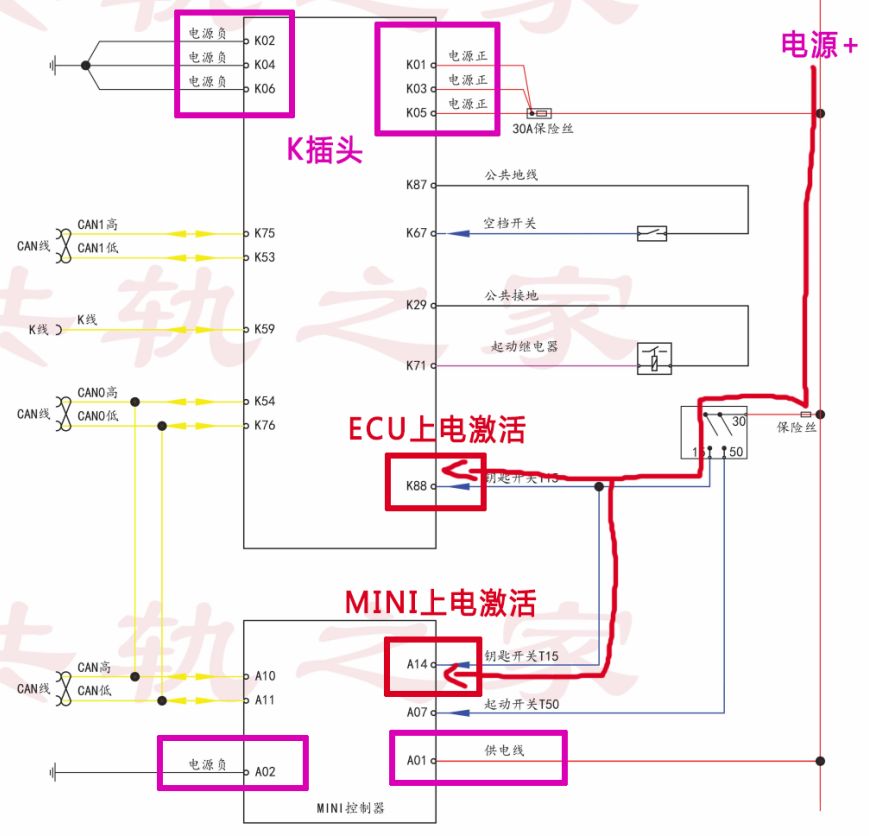
The MINI’s power-on activation: The MINI’s power-on activation wake-up line is pin A14. When the ignition switch is turned ON, T15 supplies power to the engine ECU while also providing 24V power to pin A14 of the MINI, activating the MINI. (Battery → Ignition Switch → MINI Pin A14).

03
Key Start T50 Power-On Signal Enters MINI Controller
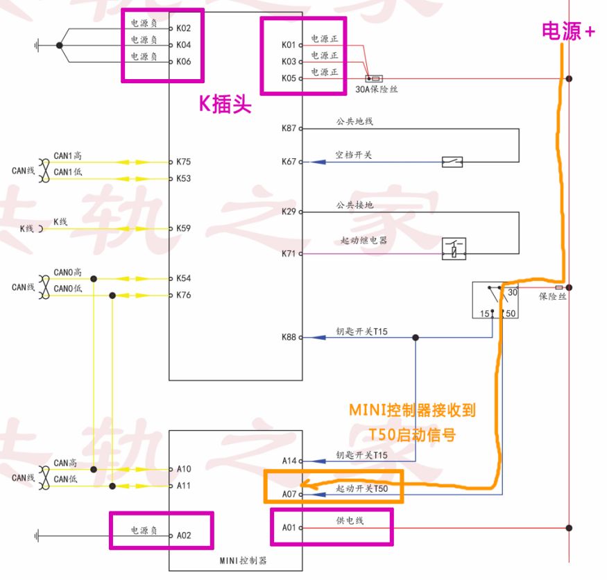
When the driver needs to start the vehicle, turning the ignition switch to the T50 start position allows the MINI controller pin A7 to receive the power from the key T50 start signal. (Battery → Ignition Switch → MINI Controller Pin A7).

04
MINI Uses CAN Communication to Output Startup Signal to ECU
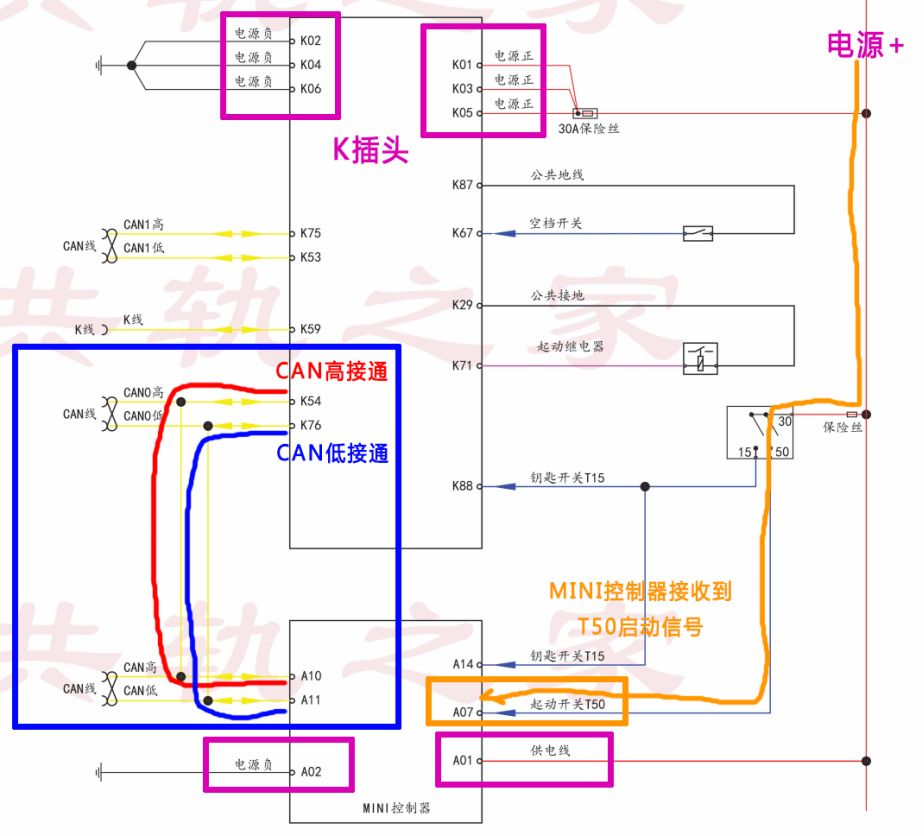
When the MINI controller pin A7 receives power from the key T50 startup signal, it uses CAN communication to send the startup signal to the engine ECU in the form of a data message.

05
ECU Collects Neutral Signal
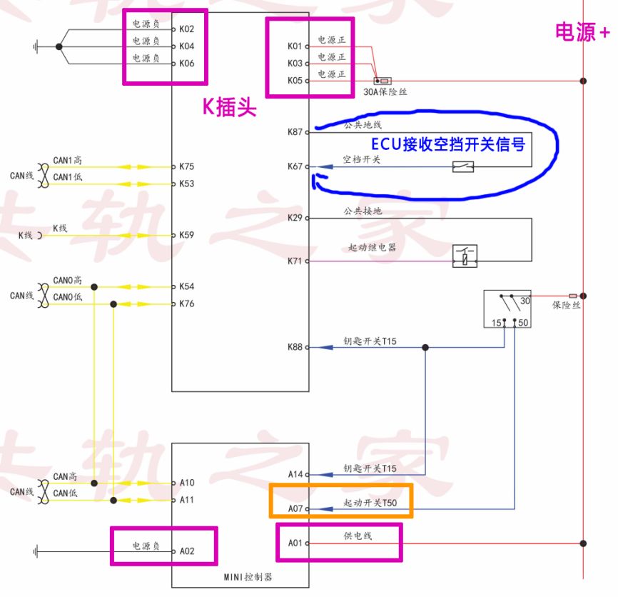
When the engine ECU receives the startup data message from the MINI, it will not control the starter relay to work yet. At this point, another starting condition must be met: the ECU also needs a neutral signal. The working principle is: ECU’s K87 outputs a common digital ground; when in the neutral position, the neutral switch closes and conducts, allowing the K67 pin to receive the digital neutral signal. At this point, this starting condition is satisfied. (ECU’s K87 → Neutral Switch → ECU’s K67).

06
Control the Starter Relay Operation
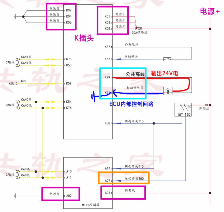
After the computer board and MINI controller are successfully powered on and activated, the MINI receives the key start signal and outputs the startup signal message to the ECU. The ECU receives the startup signal message from the MINI, and at the same time, the ECU also receives the neutral switch signal. At this point, the ECU’s K71 controls the starter relay coil circuit, closing the starter relay and enabling the starter to work.
Note: The power for the starter relay coil comes from the common high-side K29 output by the ECU, providing 24V (main relay 0). When the ignition is ON, the ECU has already output 24V common high-side. Once the starting conditions are met, the ECU can control the relay coil circuit to start.

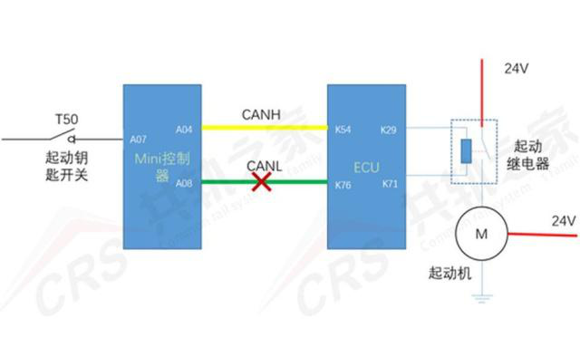
Special Note: The heavy-duty truck uses a CAN communication startup mode. If there is a fault in the CAN communication line between the MINI and the ECU, and normal communication cannot occur, the ECU cannot receive the MINI’s startup message, and the engine cannot start. Therefore, the CAN communication fault must be resolved first to ensure that the ECU can receive the startup message; otherwise, the ECU must be reprogrammed to a non-CAN startup program!
Fault Case
I have detailed the startup system controlled by the heavy-duty truck’s CAN communication. Now, let me present a fault case:
A heavy-duty truck T5G tractor, equipped with an MC07 (MAN) Bosch EDC17CV44 engine, has a blue MINI controller as its body computer. This vehicle’s design scheme utilizes a CAN communication startup strategy.
The owner reported that the vehicle could not start. The vehicle employs a CAN startup control strategy. After inspection, it was found that the K71 pin of the computer board controlling the starter relay coil circuit was corroded and open, causing the computer board to be unable to control the starter relay closure, resulting in failure to start.
Considering that replacing the ECU computer board is quite expensive, the owner generally finds it hard to accept. We designed a wiring modification solution that does not require ECU replacement to resolve the fault.
In the previously common startup control strategies, especially for Weichai National III and IV, we only needed to cut the two pins that control the relay on the computer board, ground one side of the relay coil, and connect the other side to the ignition switch T50 start.
However, for this heavy-duty truck ECU, if it does not receive the startup signal message from the MINI, the ECU will not control the fuel injection.
Therefore, when we modify the wiring, we must ensure that the MINI sends the data message to the ECU.
The wiring diagram is as follows:
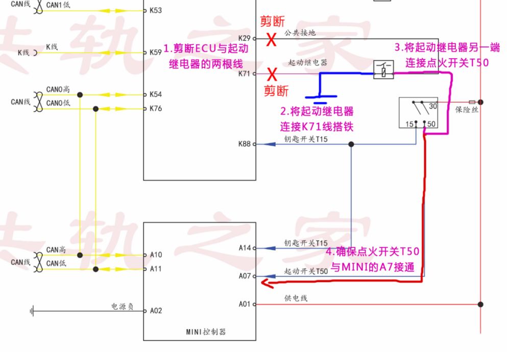
As shown in the diagram: cut the two lines between the ECU and the starter relay, ground one end of the relay, and connect the other end to the ignition switch T50 start position. At the same time, the ignition switch T50 start must also connect to the MINI’s A7 pin to allow the startup signal to enter the MINI controller.
Working Principle 1:
When the ignition switch is turned ON to T50, the starter relay is powered and closed, enabling the starter to work. However, if only the starter operates, the engine will not ignite. The engine ignites only when it receives the CAN startup message from the MINI controller.
Working Principle 2:
When we modify the wiring, keep the MINI’s A7 pin connected, allowing the startup signal to still enter normally. When the key is turned to T50, the relay closes, the starter operates, and the MINI receives the key T50 startup signal. The MINI outputs the CAN communication startup message → the ECU receives the startup message from the MINI, and the ECU controls the engine fuel injection to ignite.
Note: This solution can be used when the engine computer board controlling the starter relay pin is damaged or corroded, or when the internal module controlling the starter relay of the engine computer board is faulty.
Did everyone learn this?
If you haven’t understood it,
please follow me,and we can explore it in detail later.
You can also leave a comment at the bottom of the article.