Click the above“Zheng Motion Assistant”, stay tuned for updates!
Today, Zheng Motion Assistant will share with everyone the hardware wiring of the EtherCAT motion control card ECI2828 and how to use LabVIEW for advanced processing in continuous interpolation motion development.
1Introduction to ECI2828 Hardware
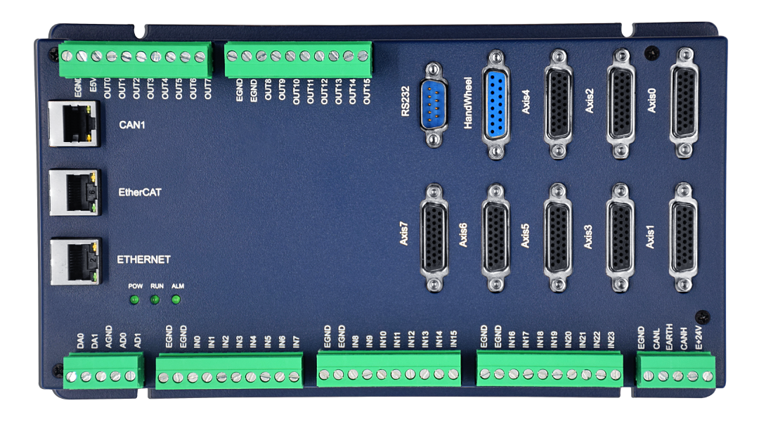
The ECI2828 series motion control card supports up to 16-axis linear interpolation, arbitrary arc interpolation, spatial arcs, helical interpolation, electronic cam, electronic gear, synchronous follow, virtual axes, and robotic commands; it uses an optimized network communication protocol to achieve real-time motion control.
The ECI2828 series motion control card supports Ethernet, RS-232 communication interfaces, and connects to computers, receiving commands from the computer for operation. It can connect to various expansion modules through EtherCAT and CAN buses, thereby expanding the number of input/output points or motion axes.
The application program for the ECI2828 series motion control card can be developed using software such as VC, VB, VS, C++, and C#. The program requires the dynamic library zmotion.dll to run. During debugging, the ZDevelop software can be connected to the controller simultaneously for convenient debugging and observation.
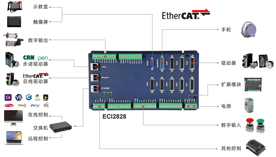
Typical connection configuration diagram of the ECI2828 series motion control card2
Motion Control Development with LabVIEW
1. Download the LabVIEW Vi function library folder “zauxdll” from the “CD materials” to your computer, and then copy it to the LabVIEW installation path under LabVIEW/user.lib.

Path of the Zauxdll function library
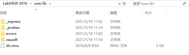 Path to paste the Zauxdll function library
2. Refer to the PC function manual to familiarize yourself with the relevant function interfaces.
(1) The PC function manual is also in the CD materials, the specific path is as follows: “CD materials\8.PC functions\Function library 2.1\ZMotion function library programming manual V2.1.pdf”
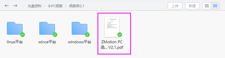
(2) In PC programming, if the Ethernet port links the controller and the industrial computer, the function interface for the Ethernet link is ZAux_OpenEth(); if the link is successful, this interface will return a link handle. By operating this link handle, control over the controller can be achieved.
ZAux_OpenEth() interface description:
|
Command 7 |
ZAux_OpenEth |
|
Command prototype |
int32 __stdcall ZAux_OpenEth(char *ipaddr, ZMC_HANDLE * phandle) |
|
Command description |
Ethernet link to the controller. |
|
Input parameters |
1 input parameter, detailed below. |
|
ipaddr |
The IP address to connect. |
|
Output parameters |
1 output parameter, detailed below. |
|
phandle |
The returned link handle. |
|
Return value |
See error code description. |
(3) Use axis parameter setting related commands to operate the link handle “g_handle” to set axis parameters for the controller. The commands related to axis parameter settings are as follows.
|
4.2 Basic Axis Parameter Initialization |
|
|
ZAux_Direct_SetAtype |
Set axis type |
|
ZAux_Direct_SetUnits |
Set axis pulse equivalent |
|
ZAux_Direct_SetInvertStep |
Set pulse output mode |
|
ZAux_Direct_SetSpeed |
Set axis speed |
|
ZAux_Direct_SetAccel |
Set axis acceleration |
|
ZAux_Direct_SetDecel |
Set axis deceleration |
|
ZAux_Direct_SetSramp |
Set axis S-curve |
|
ZAux_Direct_GetAtype |
Read axis type |
|
ZAux_Direct_GetUnits |
Read axis pulse equivalent |
|
ZAux_Direct_GetInvertStep |
Read pulse output mode |
|
ZAux_Direct_GetSpeed |
Read axis speed |
|
ZAux_Direct_GetAccel |
Read axis acceleration |
|
ZAux_Direct_GetDecel |
Read axis deceleration |
|
ZAux_Direct_GetSramp |
Read axis S-curve setting |
(4) Use axis parameter setting related commands to operate the link handle “g_handle” to set axis parameters for the controller. The commands related to advanced mode settings are as follows.
|
ZAux_Direct_SetCornerMode |
Set corner deceleration mode |
|
ZAux_Direct_SetDecelAngle |
Set the starting angle for deceleration at corners |
|
ZAux_Direct_SetStopAngle |
Set the stopping angle for deceleration at corners |
|
ZAux_Direct_SetFullSpRadius |
Set the small circle speed limit radius |
|
ZAux_Direct_SetZsmooth |
Set automatic chamfer radius |
|
ZAux_Direct_GetCornerMode |
Read corner deceleration |
|
ZAux_Direct_GetDecelAngle |
Read starting angle for corner deceleration |
|
ZAux_Direct_GetStopAngle |
Read stopping angle for corner deceleration |
|
ZAux_Direct_GetFullSpRadius |
Read small circle speed limit radius |
|
ZAux_Direct_GetZsmooth |
Read automatic chamfer radius |
Setting corner deceleration:
|
Command 181 |
ZAux_Direct_SetCornerMode |
|
Command prototype |
int32 __stdcall ZAux_Direct_SetCornerMode(ZMC_HANDLE handle, int iaxis, int iValue); |
|
Command description |
Set corner deceleration. |
|
Input parameters |
There are 3 input parameters, see below for details. |
|
handle |
Link handle. |
|
iaxis |
Axis number. |
|
iValue |
Mode setting. Bit Value Description 0 1 Reserved 1 2 Automatic corner deceleration 2 4 Reserved 3 8 Automatic small circle speed limit |
Setting corner deceleration angle:
|
Command 183 |
ZAux_Direct_SetDecelAngle |
|
Command prototype |
int32 __stdcall ZAux_Direct_SetDecelAngle(ZMC_HANDLE handle, int iaxis, float fValue); |
|
Command description |
Set the corner deceleration angle, starting deceleration angle, in radians. |
|
Input parameters |
There are 3 input parameters, see below for details. |
|
handle |
Link handle. |
|
iaxis |
Axis number. |
|
fValue |
Set corner deceleration angle. |
Setting stop deceleration angle:
|
Command 185 |
ZAux_Direct_SetStopAngle |
|
Command prototype |
int32 __stdcall ZAux_Direct_SetStopAngle(ZMC_HANDLE handle, int iaxis, float pfValue); |
|
Command description |
Set stop deceleration angle. |
|
Input parameters |
There are 2 input parameters, see below for details. |
|
handle |
Link handle. |
|
iaxis |
Axis number. |
|
pfValue |
Stop deceleration angle. |
Setting small circle speed limit radius:
|
Command 188 |
ZAux_Direct_SetFullSpRadius |
|
Command prototype |
int32 __stdcall ZAux_Direct_SetFullSpRadius(ZMC_HANDLE handle, int iaxis, float fValue); |
|
Command description |
Set small circle speed limit radius. |
|
Input parameters |
There are 3 input parameters, see below for details. |
|
handle |
Link handle. |
|
iaxis |
Axis number. |
|
Output parameters |
1 output parameter. |
|
pfValue |
Small circle radius. |
Global variable reading:
|
Command 274 |
ZAux_Direct_SetZsmooth |
|
Command prototype |
int32 __stdcall ZAux_Direct_SetZsmooth (ZMC_HANDLE handle, int iaxis, float fValue); |
|
Command description |
Global variable reading. |
|
Input parameters |
There are 3 input parameters, see below for details. |
|
handle |
Link handle. |
|
iaxis |
Axis number. |
|
fValue |
Set value. |
3. Advanced Motion with Continuous Interpolation in LabVIEW.
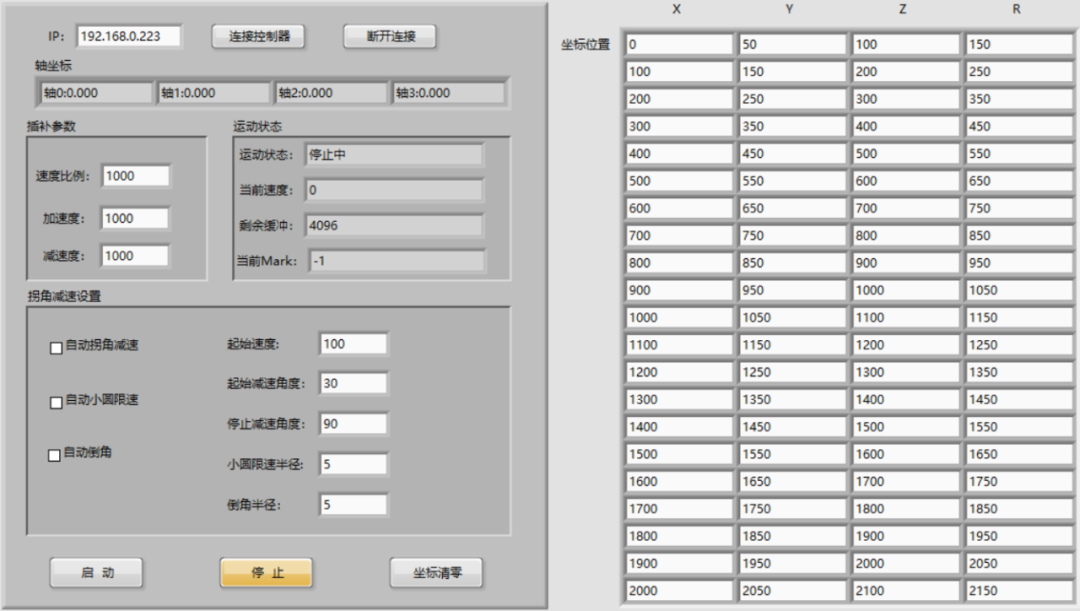
(1) Create a new Vi, in the front panel, right-click to select controls for UI design, as shown, the left side is the connection interface, and the right side shows the positions of multiple corresponding points of small line segments.
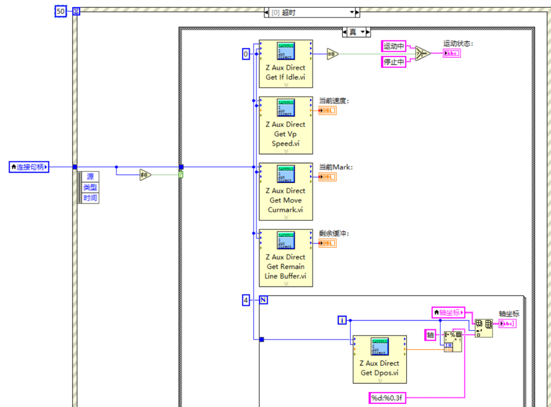
(2) In the program editing frame, select “Flat Sequence Structure” with the mouse, then right-click to select “Add Frame After,” and then add a “While Loop” inside the added frame, and within the “While Loop,” add an “Event Structure.”
Use the “Timeout Handling” in the event structure to monitor the controller’s motion status, speed, position, remaining buffer, and current mark running number.
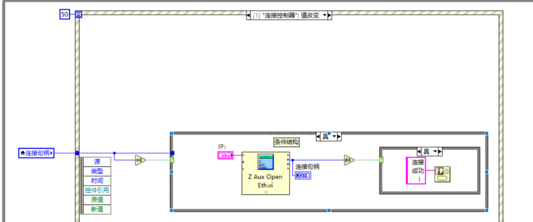
(3) Select the event structure, right-click to add an event branch, select “Connection” value change, and then use the “Z Aux Open Eth.vi” function in that event branch to connect to the controller, enabling the connect controller button functionality.
(4) Select the event structure, right-click to add an event branch, select “Disconnect” value change, and then use the “Z Aux Close.vi” function in that event branch to disconnect from the controller, enabling the disconnect button functionality.
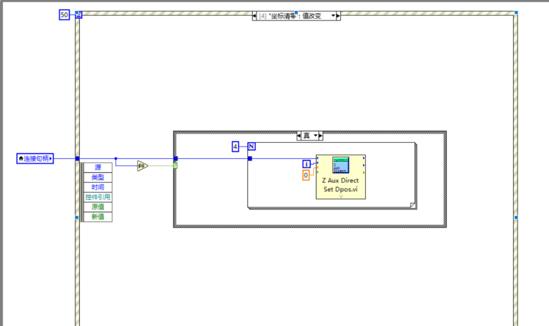
(5) Select the event structure, right-click to add an event branch, select “Zero Coordinates” value change, and then use the “Z Aux Direct Set Dpos.vi” function in that event branch to set the controller’s axis position to 0, enabling the zero coordinates button functionality.
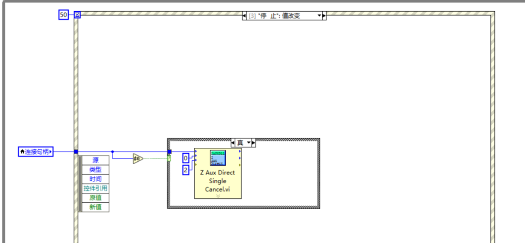
(6) Select the event structure, right-click to add an event branch, select “Stop” value change, and then use the “Z Aux Direct Single Cancel.vi” function in that event branch to stop the axis motion.
(7) Select the event structure, right-click to select the timeout event, select “Start” value change, and then use the related Vi functions in that event branch to set the controller’s motion parameters and start motion, enabling the motion button functionality.
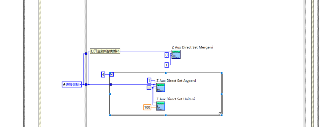
A. In the 0 frame of the “Stacked Sequence Structure” in that event branch, call the axis parameter setting related Vi functions to first set the controller’s axis parameters and enable continuous interpolation functionality.
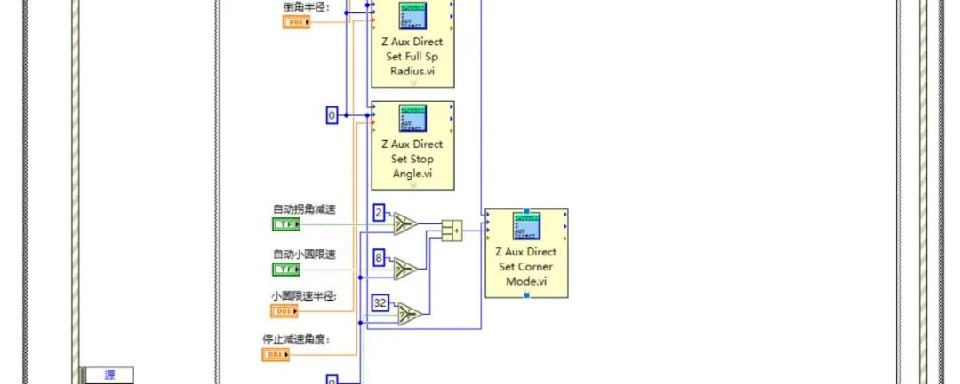
B. In the 1 frame of the “Stacked Sequence Structure” in that event branch, set the corresponding advanced mode, acceleration and deceleration, starting speed, deceleration angle, and stop angle parameters using related Vi functions to make the motion process relatively smooth.
C. In the 2 frame of the “Stacked Sequence Structure” in that event branch, call the action small line segment continuous interpolation and during the motion process, judge whether the remaining buffer size is sufficient to continue loading into the buffer, and read the current motion mark number to display on the interface.
3Debugging and Monitoring
Compile and run the routine, while connecting to the ZDevelop software for debugging, monitoring the axis parameters and motion conditions of motion control.
1. Explanation of the CornerMode Function’s Advanced Settings.
The system’s speed foresight function can plan the instructions overall, that is, plan the speeds of each segment overall, and combined with acceleration and deceleration control within the instruction segment, can keep the machine tool running at high speed to improve efficiency, making the load movement smoother, eliminating stop-and-go. The system achieves this through the Merge speed integration function.
On the other hand, to limit mechanical shocks and over-cutting while ensuring high-speed operation, deceleration recognition is also needed by identifying trajectory changes in advance.
Thus, safe deceleration can be achieved by decelerating in advance. The system achieves this through the deceleration/stop integration function and shock suppression function. Overall, the speed foresight function can enhance the overall efficiency of the machine while reducing shocks, increasing flexibility, lowering component wear, and extending equipment lifespan.
The corner deceleration function solves the problem that: when the angle between commands is too large, if still running at a high speed, a significant mechanical shock will occur at the corners, causing trajectory deviation.
The controller will recognize the angle of trajectory change between commands in advance, compare it with the size relationship of the deceleration/stop angle, and decide in advance whether to decelerate, ensuring a smooth transition at the command connection point.
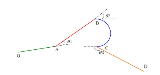
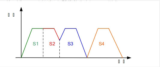
2. MonitoringOpen the oscilloscope to monitor the axis motion condition.
As shown in the figure below, when the OA transition AB segment angle is less than the deceleration angle, the S1-S2 segment does not decelerate; when the AB transition BC segment angle is greater than the deceleration angle, deceleration processing occurs during the transition process like S2-S3 segment. The BC transition CD segment angle is greater than the stop angle, speed needs to be reduced to zero as in S3-S4 segment processing.
Connect to the ZDevelop software, monitor the controller status through the axis parameters on the right side of the software, and you can also click “View” → “Oscilloscope” to open the oscilloscope to monitor the axis motion condition.
A. After enabling the chamfer mode, the graphical running effect will correspond to the chamfer situation at the corners, as shown in the comparison below:
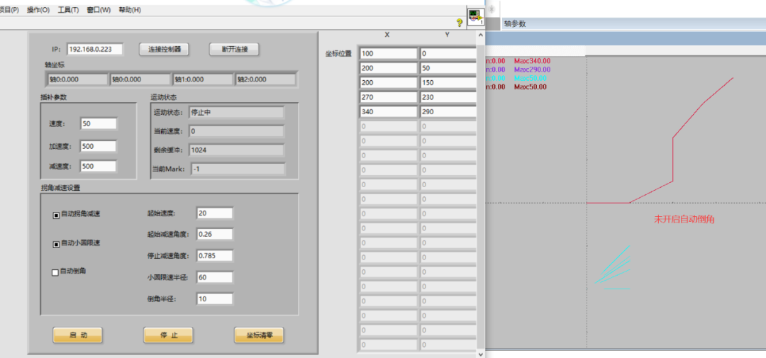 Chamfer mode not enabled
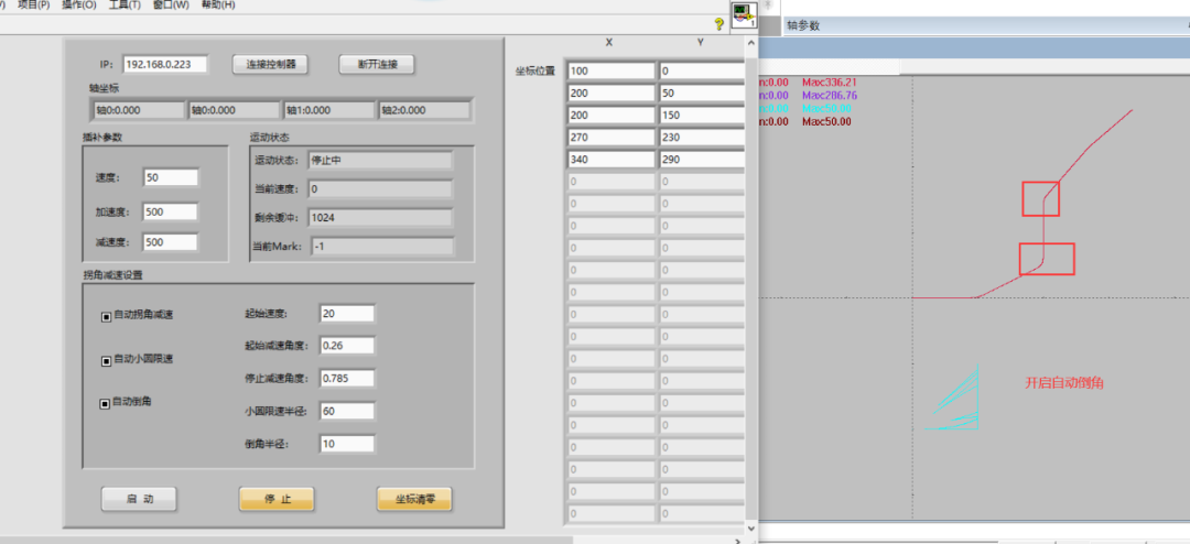
Chamfer mode enabled
B. After enabling the corner deceleration mode, when the angle at the corner reaches a certain deceleration angle or stop angle, the corner position will be processed accordingly, as shown in the figure below:
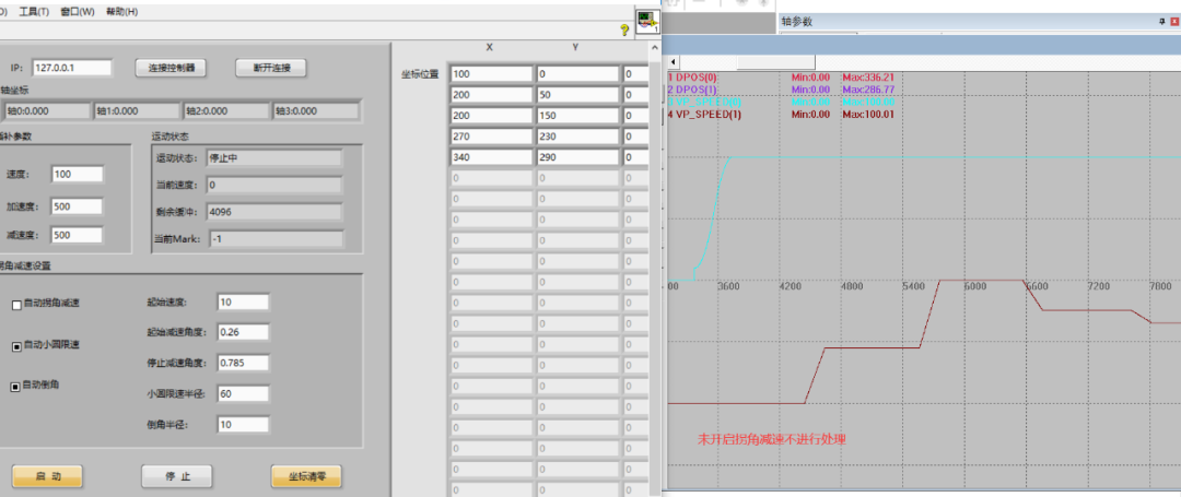
Corner deceleration mode not enabled
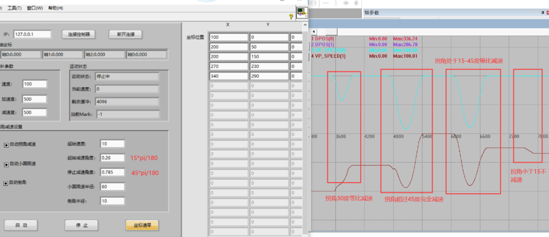
Corner deceleration mode enabled
3. ZDevelop Software Debugging Video.
This time, Zheng Motion Technology’s EtherCAT motion control card and LabVIEW build intelligent equipment (Part 5) is shared here. For more exciting content, please follow the “Zheng Motion Assistant” WeChat public account. For related development environment and example code, please consult Zheng Motion Technology sales engineers:400-089-8936.
This article is original by Zheng Motion Technology, everyone is welcome to reprint, learn together, and improve China’s intelligent manufacturing level. The copyright of this article belongs to Zheng Motion Technology, please indicate the source when reprinting.
Review of Previous Content
Application Development Tutorial for Motion Control Cards in MATLAB
EtherCAT Motion Control Card Development Tutorial in Python
EtherCAT Motion Control Card and LabVIEW Build Intelligent Equipment (Part 1)
EtherCAT Motion Control Card and LabVIEW Build Intelligent Equipment (Part 2)
EtherCAT Motion Control Card and LabVIEW Build Intelligent Equipment (Part 3)
EtherCAT Motion Control Card and LabVIEW Build Intelligent Equipment (Part 4)
Applications of EtherCAT Motion Control Card in Electronic Cam, Flying Shear, etc. (Part 1)
EtherCAT Motion Control Card PWM and Analog Output and Motion Speed Synchronization
Hardware Comparison Output of EtherCAT Motion Control Card and Encoder Latching
IO Actions of EtherCAT Motion Control Card and Synchronization of Motion Control
Real-time Program Operation and Read/Write Control of EtherCAT Motion Control Card
Applications of EtherCAT Motion Control Card in SCARA Robots and Other Commands
Motion Pause, Resume, and System Safety Settings of EtherCAT Motion Control Card
Continuous Interpolation Motion of Small Line Segments in EtherCAT Motion Control Card
Multi-axis Interpolation Motion and Handwheel Motion of EtherCAT Motion Control Card
Introduction to Auxiliary Debugging Tools and Methods for EtherCAT Motion Control Card
Bus Axis Parameter Settings and Axis Motion of EtherCAT Motion Control Card
Hardware Wiring of EtherCAT Motion Control Card and C# Single-axis Motion Control
EtherCAT Motion Control Card Hardware Wiring and C# Hardware Peripheral Read/Write and Return to Zero MotionBus Axis Parameter Settings and Axis Motion of EtherCAT Motion Control Card
About Zheng Motion Technology
Zheng Motion Technology focuses on motion control technology research and the development of general motion control software and hardware products, is a national high-tech enterprise, with main products including motion controllers, motion control cards, visual motion control integrated machines, human-machine interfaces, and expansion modules.
Zheng Motion Technology brings together outstanding talents from companies like Huawei and ZTE, while adhering to independent innovation, actively collaborating with major universities to research the basic technology of motion control, and is one of the fastest-growing companies in the domestic industrial control field, as well as one of the few companies that fully master core motion control technology and real-time industrial control software platform technology.