Introduction
Why is the top so pointy? Just kidding!
Today! I will guide you step by step to create a super cool Bluetooth speaker!
 01It has 4 major highlights!”
① Simple to make!
-
Simple circuit design!
-
Easy to solder! Most components use through-hole packages.
-
No coding required, just burn the firmware! Pure hardware design!
② Easy to use!
Power on + connect Bluetooth, and it’s ready to use!
Function description: Bluetooth connection range of 20m; supports one-click 【switch/pause/play】 music; one-click 【increase/decrease】 volume.
③ Good sound quality!
④ Detailed tutorial!
Scroll down to see circuit design description + installation tutorial + DIY cost details!
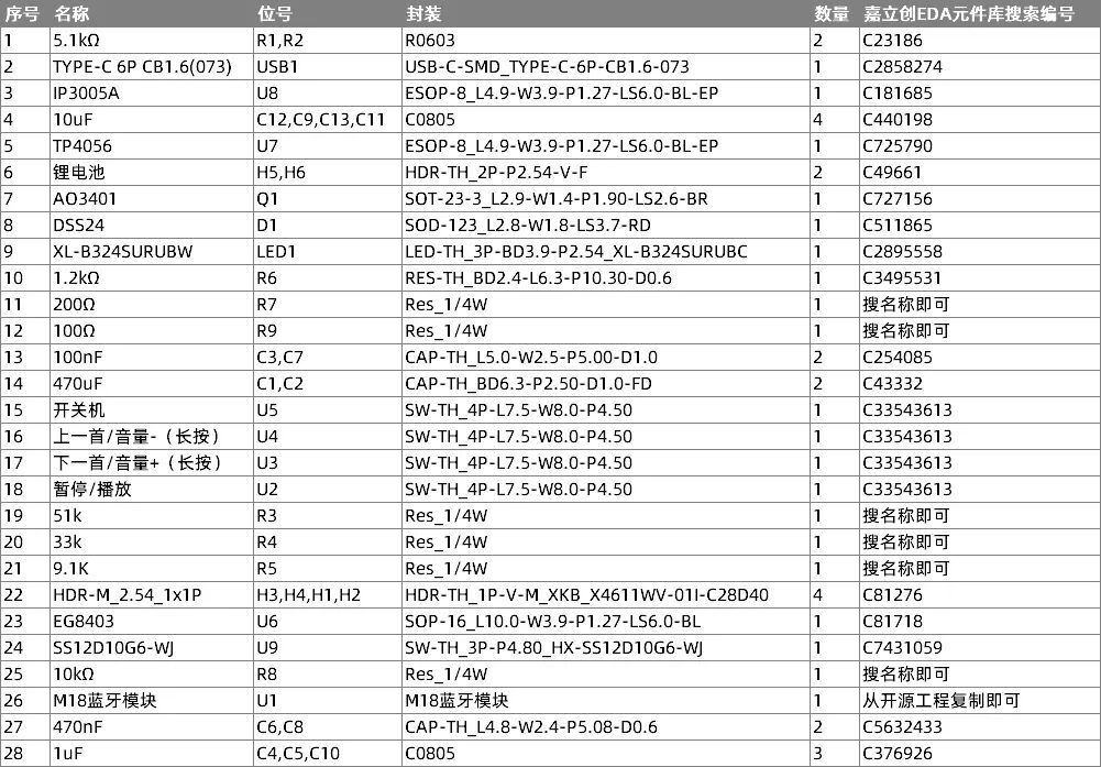
02Hardware design scheme”01 BOM List
According to the BOM list, search for components in JLCPCB EDA.
 02 Circuit Design
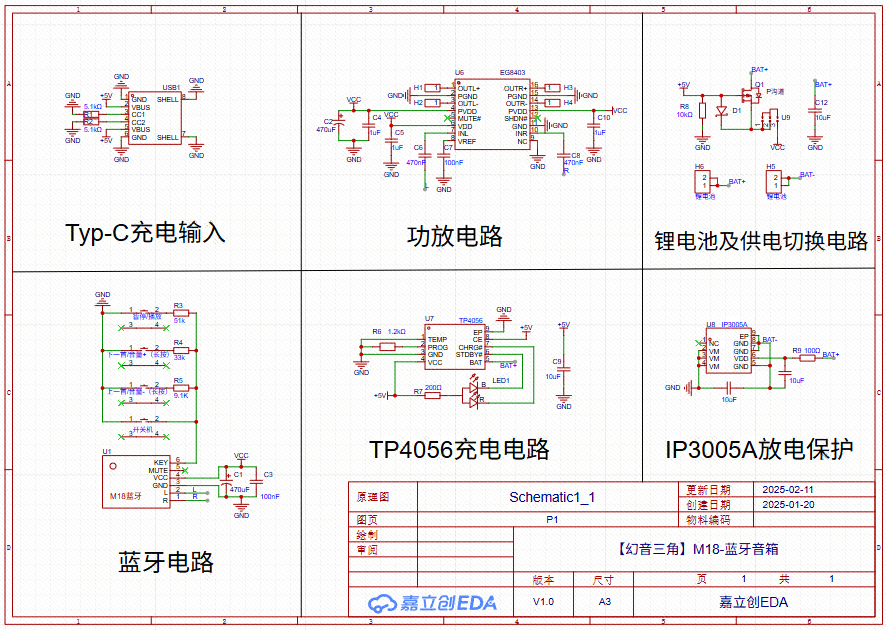
Schematic
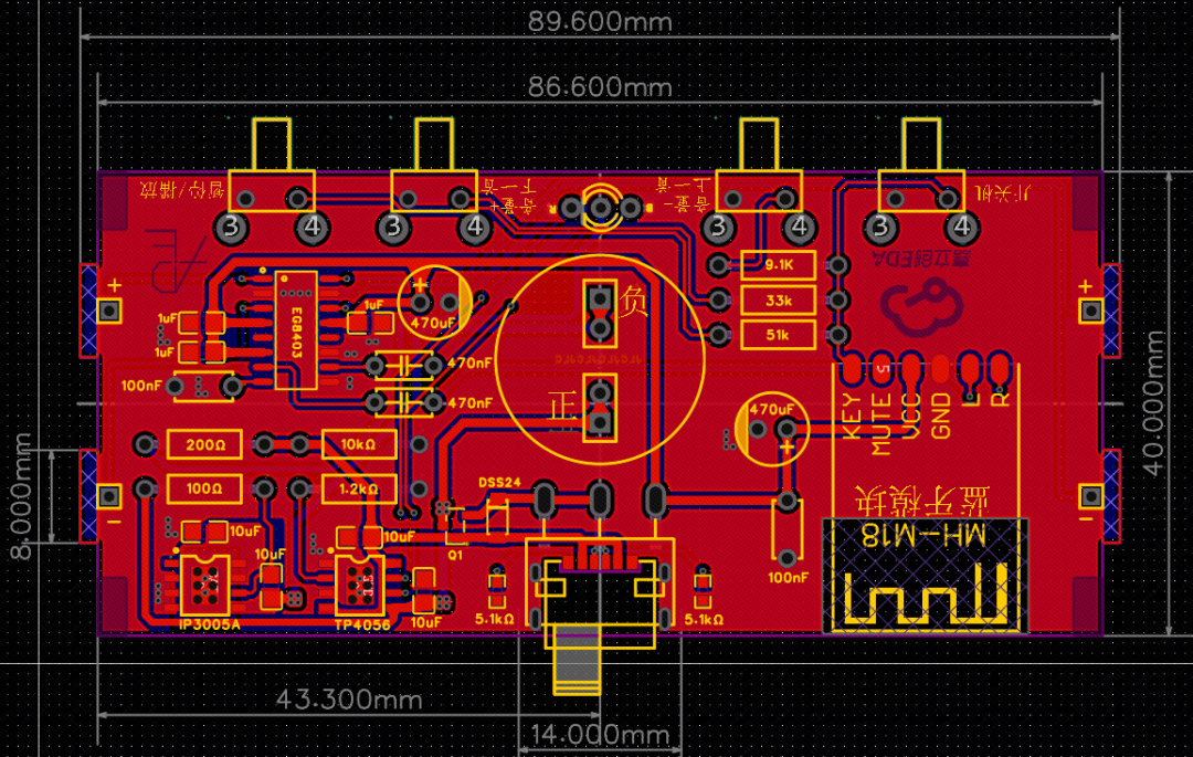
PCB Layout
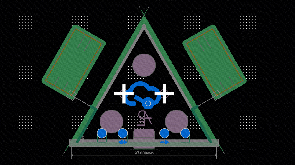
3D Case Design
03 Hardware Parameters
-
Bluetooth Chip:MH-M18
-
Amplifier Chip:EG8403, drives two 4Ω3W speakers
-
Speaker:GSPK4020057TN-4R3W
-
Battery Management Chip:TP4056, maximum charging current can reach 1000mA
-
LED Light:XL-B324SURUB, can display red and blue indicators
-
3.7V-5V power supply switching
04 Design Principle Description
① Charging Circuit & Discharge Protection Circuit:
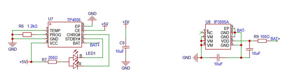
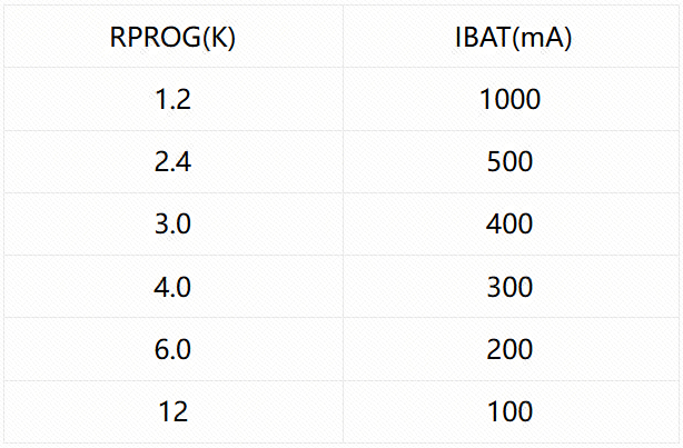
The charging current is set using a resistor connected between the PROG pin and ground. The resistor value is determined based on the desired charging current, and the following formula is used to calculate:

The relationship between RPROG and charging current can be referenced in the table below:
TP4056 has two open-drain status output pins CHRG and STDBY.
-
When the charger is in charging state, CHRG is pulled low, pin 7 connects to the red light indicating charging;
-
When the battery charging is complete, STDBY is pulled low, pin 6 connects to the blue light indicating fully charged.
-
When the battery is not connected to the charger, CHRG blinks indicating no battery installed.
② Lithium Battery and Power Switching Circuit:
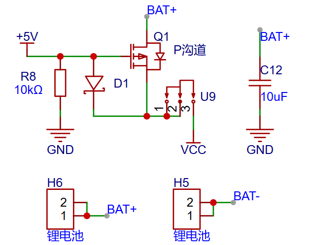
When a project has both a battery (3.7V~4.2V) and a power supply interface (5V), there is a risk of power backflow when both are connected. Generally, a power switching circuit is added to the project, where the battery powers the system when the power supply interface is not connected, and the battery stops supplying power when the power supply interface is connected.
Using a diode, PMOS, and resistors to form a power switching circuit:
When powered by the battery, the resistor R8 pulls down the gate voltage VG close to 0V, VGS < VTH, PMOS conducts, and current flows from the drain D to the source S.
When the TYP-C 5V power supply is connected, the gate voltage VG approaches 5V, VGS > VTH, PMOS turns off, and the battery current cannot flow from the drain D to the source S. At this time, the 5V power supply current flows through diode D1 to supply power to the system at VCC.
It is important to note that the selected PMOS device’s VGSth should not be too high, otherwise the battery voltage cannot saturate and conduct. Although it can still be used, the MOSFET may overheat and potentially burn out. Additionally, if the battery voltage is higher than the input voltage, this power switching circuit cannot be used, which should be noted.
Basic structure of PMOS:
PMOS (P-type Metal-Oxide-Semiconductor) is a P-type metal-oxide-semiconductor field-effect transistor. It mainly consists of a source (Source, S), drain (Drain, D), and gate (Gate, G). The structural schematic is as follows:
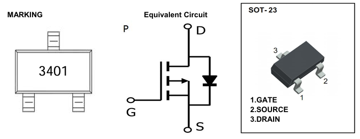
PMOS conduction principle:
When the gate voltage VG is lower than the source voltage VS, a conductive channel forms beneath the oxide layer under the gate. Specifically, when VGS=VG-VS is less than the PMOS gate threshold voltage VGSth, PMOS conducts. According to the MOSFET datasheet, the minimum gate threshold voltage VGSth is 0.7V, typical value is 0.9V, and maximum value is 1.3V.
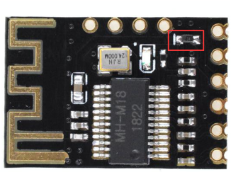
③ Bluetooth Chip Considerations:
Since two power supply methods are used, according to the Bluetooth chip MH-M18 datasheet, it is important to note that the chip is factory set to be powered by 5V. If you need to use a3.7V lithium battery for power, you need to replace the diode (as shown) with a 0603 0-ohm resistor, or directly short the pads.。
 03Installation Instructions”01 Soldering Precautions
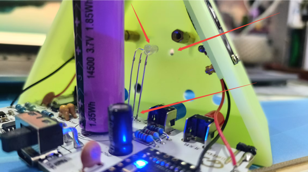
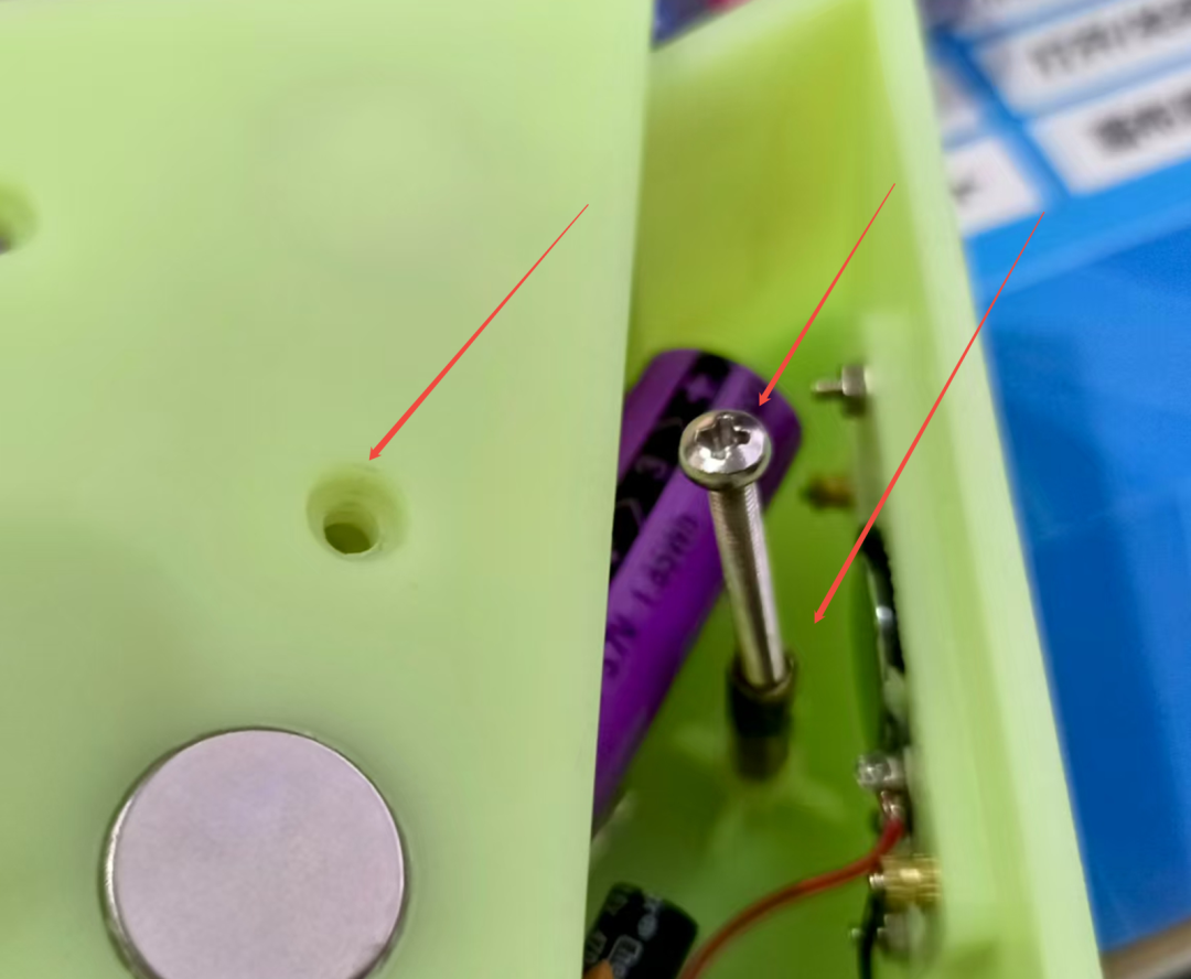
When soldering the LED pins, you need toachieve this height, so that the LED can fit through the reserved hole in the 3D case.
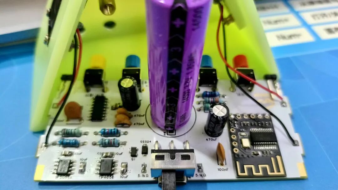
02 Case Assembly and Fixing
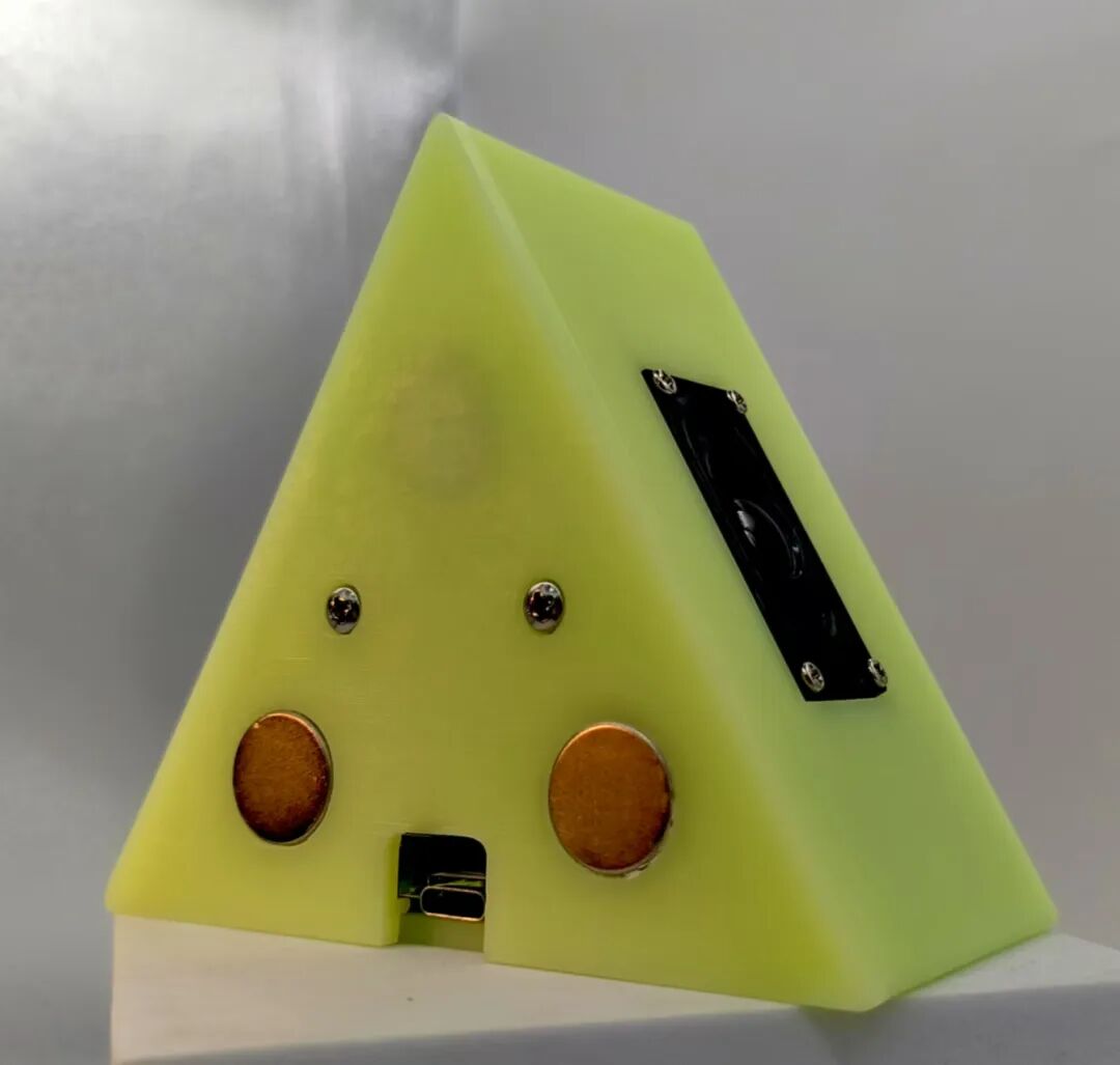
After soldering is complete, install the case..The case uses JLCPCB 3D printed UV-cured resin, meeting the free sample requirements.
Use M2*8 screws + any M2 nuts tofix the speaker..
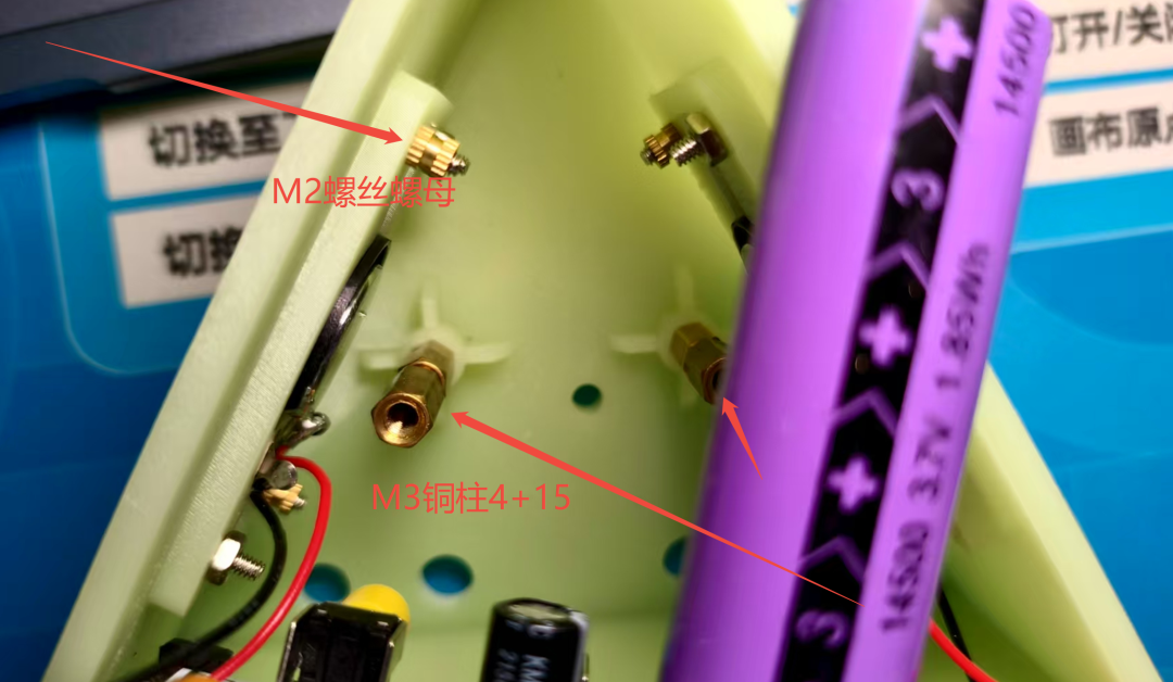
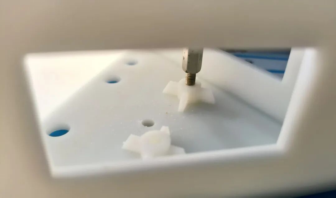
Fix the back cover: First, screw in an M3 copper pillar at the bottom, the length of the copper pillar should be as long as possible (suggested M3* 4+30mm), then use appropriately sized cross screws to fix it, being careful not to tighten too much, as the 3D printed structure has low strength and may warp.
That’s it!
Mission accomplished!
Yes, it’s that simple!
And you have a super cool speaker with a pointy top~

 04Open Source URL”
BOM cost
35 yuan
【PCB】 and 【3D case】
Both can be sampled for free~
Get free sample coupons at:
[1]PCB:https://www.jlc.com/newOrder/#/collectCoupons
[2]3D:https://www.jlc-3dp.cn/freePrint?freeShareId=412845442199797762
05Open Source URL”
This project is open source!
——Want to replicate it?? Want to give a thumbs up to the author?? You can copy the open source URL to go to the original text.
Open Source URL:
https://oshwhub.com/course-examples/huan-yin-san-jiao-m18-lan-ya-yin-xiang
Scan the code to directly access the original text.

 *Event URL: https://oshwhub.com/activities/nuedc2025
*This article is a reprint of user creations from the “Lichuang Open Source Hardware Platform”, and the description may have been edited or may not be the latest version. Please refer to the specific project description on the “Lichuang Open Source Hardware Platform”.
All images, fonts, trademarks, and other assets involved in the project and project description belong to their respective owners. If there is any infringement, please contact for removal.
The project open source agreement is subject to the specific project description and requirements of the open source hardware platform.
If you like it, give me a thumbs up! Click to read the original text to view the original project