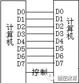
PLC communication can be divided into communication between PLC and external devices, as well as communication between PLC and internal system devices based on device classification. Depending on the communication objects, it can be further divided into the following situations.Communication Between PLC and External Devices:1. Communication between PLC and computers: Communication between PLC and the upper computer in programming, monitoring, debugging, or network control systems.2. Communication between PLC and general external devices: Communication between PLC and external devices with general communication interfaces (such as RS232, RS422/485, etc.).Communication Between PLC and Internal Devices:1. Communication between PLC and remote I/O.2. Communication between PLCs.Basic Types of Communication: Parallel Communication and Serial CommunicationParallel communication transmits each binary bit of data using separate wires, connecting the sending and receiving ends in parallel; as shown in the figure below.
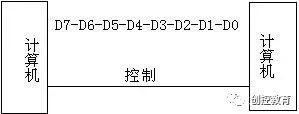
 Serial communication connects the sender and receiver with a pair of connecting wires, transmitting each binary bit of data in a specified order along the same connection wire, one after the other, as shown in the figure below:
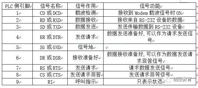
 PLC communication generally uses serial communication. Standard Serial Interface refers to the input/output lines used for communication line connections. The lines connected to parallel communication are called parallel interfaces; those connected to serial communication are called serial interfaces. In PLC systems, common standard serial interfaces mainly include RS232, RS422, and RS485 interfaces. RS232/422/485 are the most commonly used communication interfaces in PLC systems: The RS232 interface is the most common standard serial interface in computers and PLC control systems, typically using 9-pin or 25-pin connectors, with the signal names, codes, and pin meanings shown in the following table:
 The RS422 interface is a common standard serial interface in computers and PLC control systems, known as the “balanced voltage digital interface.” This interface typically uses a 9-pin connector, with the signal names, codes, and pin meanings shown in the following table:
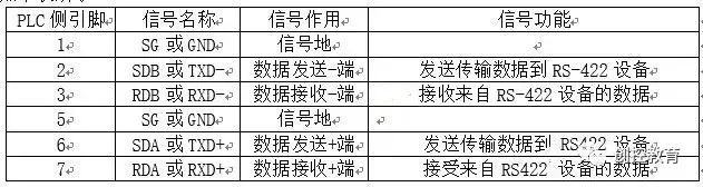 The RS-485 interface is a standard serial interface developed based on RS-422, also using “balanced differential drive”. This interface meets all the technical specifications of RS-422 and can be used for RS-422 communication, typically using a 9-pin connector or terminal block connection, with the signal names, codes, and pin meanings the same as RS-422. Communication Functions of Mitsubishi FX Series PLC 1. N:N Network Function: This allows a maximum of 8 FX series PLCs to connect via RS-485 communication, facilitating soft component interconnection and information exchange. One PLC acts as the master, while the others are slaves (i.e., master and slave stations). Each PLC has a designated data sharing area in its auxiliary relays and data registers. The data area assigned to one PLC will automatically be transmitted to the corresponding area of other stations, and vice versa for the data areas assigned to other PLCs.
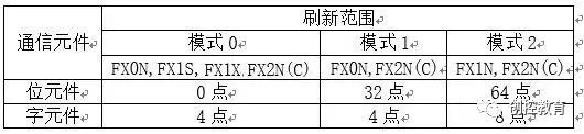
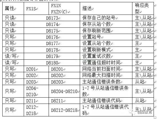 Explanation of Special Data Registers Network Settings: N:N network settings are effective only when the program is running or the PLC is powered on. (1) Set the workstation number (D8176): The value range for D8176 is 0-7; the master station should be set to 0, and slave stations should be set to 1-7. (2) Set the number of slaves (D8177): This setting applies only to the master station, with a setting range of 1-7, defaulting to 7. (3) Set the refresh range (D8178): The refresh range refers to the range of auxiliary relays and data registers shared between the master and slave stations. The refresh range is set by D8178 of the master station and can be set to values 0, 1, or 2, corresponding to the refresh ranges shown in the following table:
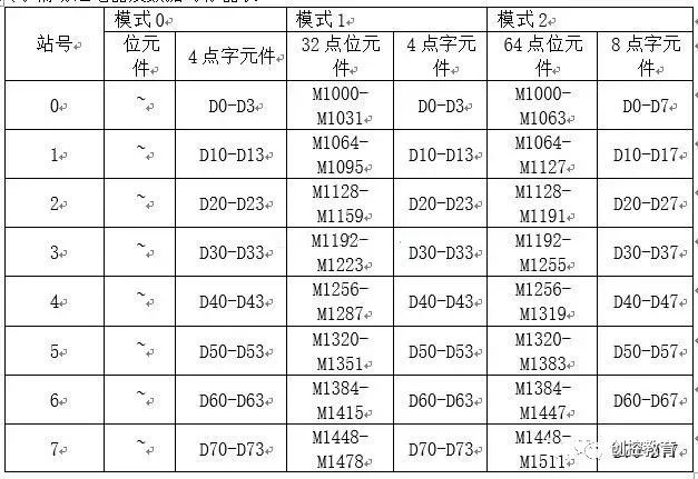
 Shared Auxiliary Relays and Data Register Table:
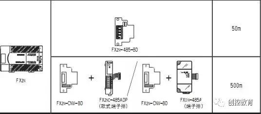
 Not all FX series PLCs have the capability for parallel linking. FX0S, FX1, and FX2(C) series PLCs do not have network linking capabilities.
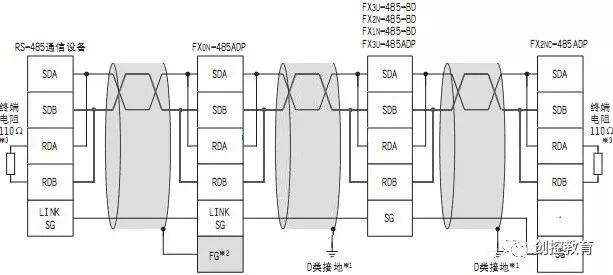
 4. Wiring for Network Link Communication N:N Network 1 Pair Wiring Method
 Example of N:N Network Programming: 3 FX2N series PLCs exchange data through the N:N network. Requirements: 1. The master station’s X0-X3 controls the slave station’s Y10-Y132. 1st slave’s X0-X3 controls the 2nd slave’s Y14-Y173. 2nd slave’s X0-X3 controls the master station’s Y20-Y23 master station program.
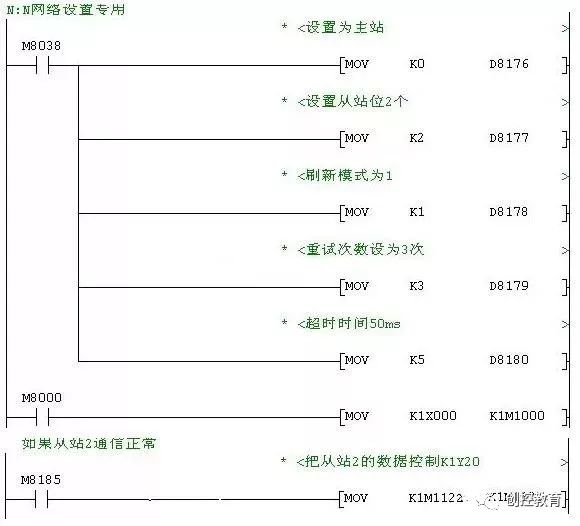 Slave 1 Program
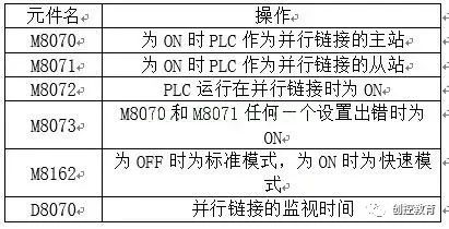
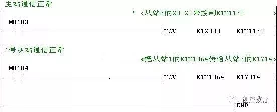 Slave 2 Program 2. Parallel Linking Function: This connects 2 PLCs of the same FX series for software interlinking and information exchange. Special auxiliary relays and special data register tables for parallel linking:
 Data Sharing Area Table for Parallel Linking:
2. Communication devices suitable for parallel linking of FX series PLCs: FX0S and FX1 series PLCs cannot perform parallel linking. Additionally, parallel linking requires specialized communication devices such as 232/422/485 communication boards, adapters, etc. The following table lists the combinations of PLCs and communication devices for parallel linking.
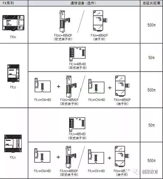
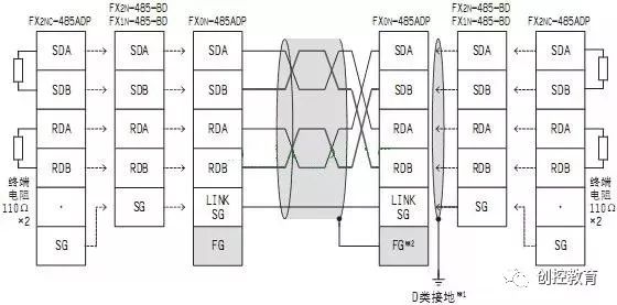
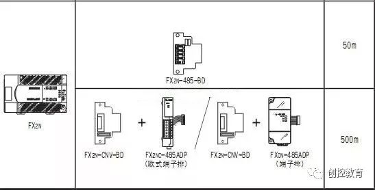 4. Wiring for Parallel Link Communication 1. Cases for FX1S, FX1N, FX1NC, FX2N, FX2NC programmable controllers 1. Wiring for 1 Pair
2. Wiring for 2 Pairs
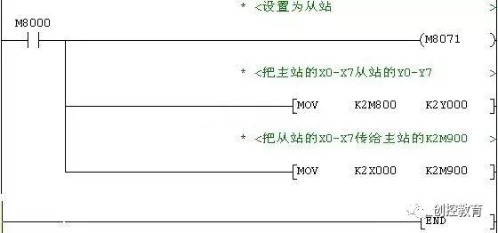
 5. Example of Parallel Linking: Requirements: 2 FX2N series PLCs perform parallel linking; the master station’s X0-X7 controls the slave’s Y0-Y7; the slave’s X0-X7 controls the master station’s Y0-Y7; master station program and explanation:
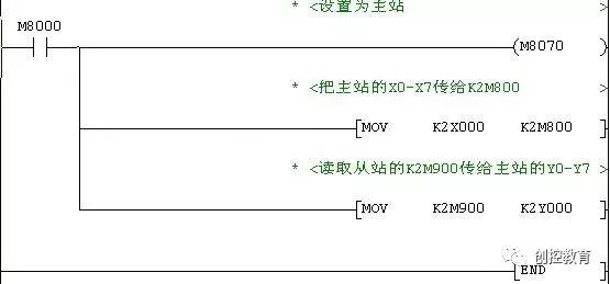 Slave Program
 3. Communication Protocols of PLC: To reliably send and receive data, both communicating parties must have specified data formats, synchronization methods, transmission rates, error correction methods, control characters, etc., which requires a dedicated communication protocol. 1. Dedicated Protocol Communication: This refers to the communication method for data exchange between PLC and external devices by installing dedicated communication tool software on external devices. 2. No Protocol Communication: This requires only simple settings for data formats, transmission rates, start/stop codes, etc., allowing direct data sending and receiving between PLC and external devices. 3. Bidirectional Protocol Communication: This method uses the PLC communication module’s information format via communication interfaces for data sending and receiving with external devices.
(Content sourced from the internet, copyright belongs to the original author)Disclaimer:If there are copyright issues, please contact for removal!
No individual or organization bears related legal responsibilities.
Recommended Reading:
Free Gift | Collection of Video Recordings of Public Courses from Chuangkong Education
As an engineer, how can you not have this certificate?
United as one, brave to forge ahead, Chuangkong Education offline students’ San Tai Mountain expansion activity.
Video Replay of Public Course | June 28, Siemens DB Data Block Usage Methods and Precautions
Latest Industrial Control Programming Software Download (updated in real-time)
As an electrician, where do you think your prospects lie?
Second half of 2019:Empty yourself and let your heart return to zero!