 Search WeChat
 Technical Training
Differences Between RS232 and RS485 Interfaces
1. Physical Structure of the Interface
1. RS232 Interface:
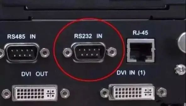
One of the computer communication interfaces, RS-232 typically appears in the form of 9 pins (DB-9) or 25 pins (DB-25). Usually, personal computers have two sets of RS-232 interfaces, referred to as COM1 and COM2.
2. RS485:
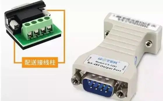
RS485 does not have a specific physical shape and is adopted based on the actual engineering situation.
2. Electronic Characteristics of the Interface
1. RS232: The signal level value of the transmission level signal interface is relatively high (signal ‘1’ is ‘-3V to -15V’, signal ‘0’ is ‘3 to 15V’), which can easily damage the circuit chips of the interface. Moreover, it is not compatible with TTL levels (0~'<0.8v’, 1~’>2.0V’), so a level conversion circuit is needed to connect with TTL circuits. Additionally, its anti-interference capability is poor.
2. RS485: The differential signal logic ‘1’ is represented by a voltage difference of + (2—6) V between the two wires; logic ‘0’ is represented by a voltage difference of – (2—6)V. The signal level of the interface is lower than that of RS-232, which makes it less likely to damage the interface circuit chips, and this level is compatible with TTL levels, making it easy to connect with TTL circuits.
3. Communication Distance
1. RS232: The transmission distance of RS232 is limited, with a maximum standard transmission distance of 15 meters, and it can only communicate point-to-point, with a maximum transmission rate of 20kB/s.
2. RS485: The maximum wireless transmission distance of RS485 is 1200 meters. The maximum transmission rate is 10Mbps, and only at a transmission rate of 100Kb/S can the maximum communication distance be achieved. Using impedance-matched, low-loss dedicated cables can reach 1800 meters! Beyond 1200 meters, repeaters can be added (up to 8), making the transmission distance close to 10Km.
4. Support for Multi-Point Communication
RS232: The RS232 interface only allows one transceiver to be connected on the bus and cannot support multi-station transceiver capabilities, so it can only communicate point-to-point and does not support multi-point communication.
RS485: The RS485 interface allows up to 128 transceivers to be connected on the bus. This allows for multi-station communication, enabling users to easily establish a device network using a single RS485 interface.
5. Differences in Communication Lines
RS232: Can use three-core twisted pair, three-core shielded lines, etc.
RS485: Can use two-core twisted pair, two-core shielded lines, etc. In low-speed, short-distance, and interference-free situations, ordinary twisted pairs can be used; conversely, in high-speed, long-distance transmission, dedicated RS485 cables (STP-120Ω (for RS485 & CAN) one pair of 18AWG) with impedance matching (usually 120Ω) must be used, and in environments with severe interference, armored twisted shielded cables (ASTP-120Ω (for RS485 & CAN) one pair of 18AWG) should be used.
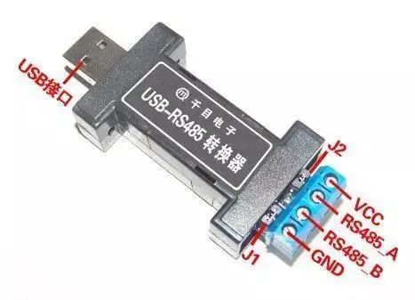
Supplement: Since the transmission distance of RS232 is only 15 meters, what is its use? In fact, it is widely used to connect various devices, such as monitoring, upgrading, or debugging other equipment. Its functionality is similar to USB. As USB ports become more common, more devices that convert USB to RS-232 or other interfaces will emerge. Through USB interfaces, more RS-232 devices can be connected, not only achieving higher transmission speeds and true plug-and-play but also overcoming the disadvantage of USB interfaces not being able to transmit over long distances (USB communication distance is within 5 meters).
Common Communication Protocols
Before starting this topic, we should understand a question I have always been confused about.
The difference between RS485 and MODBUS: RS485 is a physical interface, simply put, it is hardware; MODBUS is an international standard communication protocol used for data exchange between devices from different manufacturers (generally for industrial purposes); the so-called protocol can also be understood as a ‘language’, simply put, it is software.
Generally, two devices transmit data through the MODBUS protocol: it was initially used with RS232 as the hardware interface (that is, the serial communication port (COM port) on ordinary computers); there are also RS422 and commonly used RS485, which is used more in general industrial sites due to its long transmission distance. The MODBUS protocol is divided into three modes: MODBUS RTU, MODBUS ASCII, and the later developed MODBUS TCP. The first two (MODBUS RTU, MODBUS ASCII) use serial communication (RS232, RS422, RS485) as their physical hardware interface. MODBUS TCP, on the other hand, is developed to follow the trend of today’s world, where everything can be connected via Ethernet or the Internet for data transmission. Thus, the MODBUS TCP mode has emerged, where the hardware interface is the Ethernet port, which is the network port generally used on our computers.
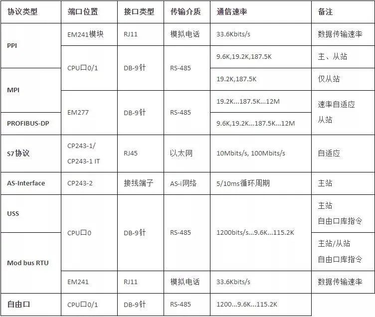
Then we can understand the various communication protocols supported by S7-200 PLC through an image.
1. PPI Communication
PPI is a communication protocol developed by Siemens specifically for the S7-200 series PLC. It is built into the S7-200 CPU. The PPI protocol is physically based on the RS-485 port, and PPI communication can be achieved through shielded twisted pairs. The PPI protocol is a master-slave protocol. The master device sends requests to the slave device, and the slave device responds; the slave cannot actively send information. The master communicates with the slave through a shared connection managed by the PPI protocol. The PPI protocol does not limit the number of masters communicating with any slave, but in a network, the number of masters cannot exceed 32. The most basic use of the PPI protocol is to enable Siemens Step7-Micro/Win programming software to upload and download programs and facilitate communication between Siemens Human-Machine Interface and PC.
2. MPI Communication
MPI (Multipoint Interface) is the interface for SIMATIC S7 multipoint communication, suitable for communication between a small number of stations, commonly used for short-distance communication between host computers and a few PLCs. By using Profibus cables and connectors, the MPI programming port of the S7-300 or S7-400 CPU can be connected to the PPI communication port of the S7-200 CPU, as well as the programming port (MPI/DP port) of the host computer’s network card via Profibus or MPI cables. The network can also exclude the PC and only include PLCs.
The communication rate of MPI is 19.2k~12Mbit/s, but the maximum rate when directly connecting to the S7-200 CPU communication port is usually 187.5kbit/s (limited by the maximum communication rate of the S7-200 CPU). Up to 32 stations can be on the MPI network, and the maximum communication distance of a network segment is 50 meters (when the communication baud rate is 187.5kbit/s), and longer distances can be extended through RS-485 repeaters. MPI allows master-master communication and master-slave communication, with each S7-200 CPU communication port allowing up to 4 connections.
The MPI protocol cannot communicate with an S7-200 CPU serving as a PPI master; when communicating with S7-300 or S7-400, it must ensure that this S7-200 CPU cannot also act as a PPI master, and Micro/Win cannot access an S7-200 CPU serving as a PPI master via the MPI protocol. The S7-200 CPU can only act as an MPI slave, meaning S7-200 CPUs cannot communicate with each other via the MPI network but can only communicate with each other via PPI.
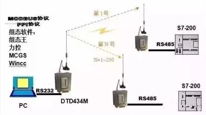
3. Modbus Communication
Modbus was invented by Modicon (now a brand of Schneider Electric) in 1979 and is the first truly industrial bus protocol used in the field. To better promote and facilitate the use of Modbus in distributed applications based on Ethernet, Schneider Electric has transferred ownership of the Modbus protocol to the IDA (Interface for Distributed Automation) organization and established the Modbus-IDA organization, laying the foundation for the future development of Modbus. In China, Modbus has become a national standard GB/T19582-2008. According to incomplete statistics, as of 2007, the number of Modbus nodes installed has exceeded 10 million.
The Modbus protocol is a common language used in electronic controllers. Through this protocol, controllers can communicate with each other, and between controllers and other devices over a network (such as Ethernet). It has become a common industrial standard. With it, control devices produced by different manufacturers can be connected into an industrial network for centralized monitoring. This protocol defines the message structure that a controller can recognize, regardless of the network used for communication. It describes the process by which a controller requests access to other devices, how to respond to requests from other devices, and how to detect errors and log them. It specifies the common format for message domain structure and content. Modbus operates in a single master, master/slave communication mode, where only one master can exist on a Modbus network, while there can be several slaves.
Modbus has the following features:
1. Standard and open, users can use the Modbus protocol freely and confidently without paying licensing fees or infringing intellectual property rights. Currently, over 400 manufacturers support Modbus, with over 600 products supporting it.
2. Modbus can support multiple electrical interfaces, such as RS-232, RS-485, and can also be transmitted over various media, such as twisted pairs, fiber optics, and wireless.
3. The frame format of Modbus is simple, compact, and easy to understand. It is user-friendly and easy for manufacturers to develop. Note: S7-200 only supports the Modbus RTU protocol and does not support the Modbus ASCII protocol;
4. ProfiBus Communication
As one of the many fieldbus family members, ProfiBus is the most widely used fieldbus standard in the European industry and is currently one of the internationally accepted fieldbus standards. ProfiBus is a unit-level, field-level SIMATIC network suitable for transferring medium to small amounts of data. Its openness allows numerous manufacturers to develop their products that comply with the ProfiBus protocol, which can be connected to the same ProfiBus network.
ProfiBus is an electrical network, and the physical transmission medium can be shielded twisted pairs, fiber optics, or wireless transmission. It officially became the international standard for fieldbuses in 1989. PROFIBUS is an international, open fieldbus standard that does not depend on the device manufacturer, and the transmission speed can be selected in the range of 9.6kbaud to 12Mbaud. When the bus system starts, all devices connected to the bus should be set at the same speed. PROFIBUS is widely used in manufacturing automation, process industry automation, and other fields such as building, transportation, and power automation. PROFIBUS is also a fieldbus technology used for workshop-level monitoring and data communication and control of field devices, allowing decentralized digital control and field communication networks from field device layers to workshop-level monitoring, providing feasible solutions for comprehensive factory automation and intelligent field devices.
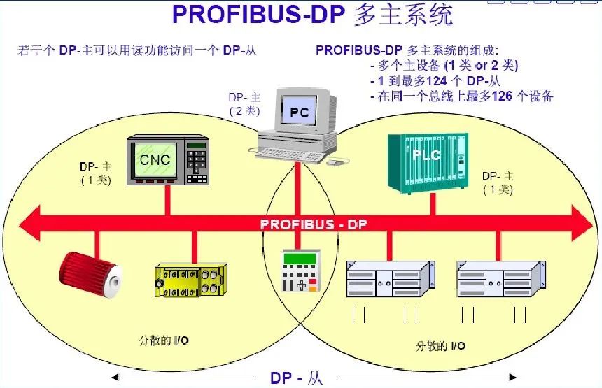
5. USS Communication
USS (Universal Serial Interface) is a communication protocol developed by Siemens specifically for drive devices, which has undergone continuous development and improvement over the years. Initially, USS was used for parameterization of drive devices, focusing more on parameter settings. It is widely used in connections between drive devices and operating panels, debugging software (such as DriveES/STARTER).
Recently, due to its simple protocol and low hardware requirements, USS has increasingly been used for communication with controllers (such as PLCs) to achieve general-level communication control. (Note: USS provides a low-cost, relatively simple communication control method; due to its design, USS cannot be used in situations where high communication speed and data transmission volume are required. In such cases, a more real-time communication method, such as PROFIBUS-DP, should be chosen. When designing the system, this limitation of USS must be considered.
For example, if USS communication control is used for a dozen or even dozens of frequency converters in applications requiring high-speed synchronization (such as paper production lines), the effect can be imagined.
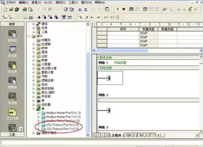
All Siemens frequency converters come with an RS485 communication port, with the PLC as the master, allowing a maximum of 31 frequency converters as slaves in the communication circuit. Based on the addresses of each frequency converter or using broadcasting, it is possible to access the frequency converters that need communication. Only the master can send communication request messages, and the address character in the message specifies the slave to which data is to be transmitted. The slave can only send data to the master after receiving the master’s request message; slaves cannot exchange data directly with each other. Before using the USS protocol, the Siemens instruction library needs to be installed. The USS protocol instructions are in the STEP7—MICRO/WIN32 instruction tree in the library folder, providing 14 subprograms, 3 interrupt programs, and 8 instructions to support the USS protocol. When an instruction is called, one or several subprograms will be automatically added.
The basic characteristics of the USS protocol are as follows:
■ Supports multi-point communication (thus applicable on networks like RS 485)
■ Uses a single master ‘master-slave’ access mechanism
■ A maximum of 32 nodes can exist on a network (maximum of 31 slaves)
■ Simple and reliable message format, making data transmission flexible and efficient
■ Easy to implement and cost-effective
The working mechanism of USS is that communication is always initiated by the master. The USS master continuously polls each slave, and the slaves decide whether and how to respond based on the received instructions. Slaves will never actively send data.
Slaves should respond under the following conditions:
1. The received master message is error-free;
2. And this slave is addressed in the received master message.
HISTORY/Recommended Previous Issues
Complete question bank for 2021 Electrical Engineer Junior Exam (including answers)
Is troubleshooting frequency converter faults difficult? Just one click!
Do you not have this tool to review all electrical exam questions in one click?
Which of the five major electrical drawing software (CAD, Eplan, CADe_simu…) do you prefer?
The latest electrical version CAD drawing software, with a super detailed installation tutorial!
Latest electrical drawing software EPLAN, with a super detailed installation tutorial!
Common problems faced by beginners using S7-200 SMART programming software (with download links)
Super comprehensive electrical calculation EXCEL spreadsheet, automatically generated! No need to ask for electrical calculations!
Bluetooth headsets, electrical/PLC introductory books are given away? Come and get your electrical gift!
Basic skills for PLC programming: Ladder diagrams and control circuits (with 1164 practical cases of Mitsubishi PLC)
Still can’t understand electrical diagrams? Basic electrical diagram reading, simulation software is available, quickly get started with theory and practice!
12 free electrical video courses, 10GB software/electronic book materials, 30 days of free live electrical courses are given away!

Don’t forget to like + follow! 
 Click “Read the Original” to learn PLC/electrical courses for free!