In order to help students memorize the content of the exam questions and to ensure that they pass the initial or retest as soon as possible, we have been working hard to improve our service quality.
Given the large number of low-voltage electrician exam questions and the difficulty students have in remembering them, we have summarized the relevant knowledge points in the exam questions by categorizing them based on common keywords. This way, each exam question corresponds to related knowledge point explanations, making it easier for students to understand the questions better. This helps students gain a comprehensive understanding of specific electrical circuits or devices through multiple related questions, allowing for a multi-faceted understanding of the subject, achieving quick memorization, and improving pass rates.
1. Definition
A multimeter, also known as a multimeter or a three-function meter, is a multi-purpose instrument frequently used by electricians. An analog multimeter is essentially a magnetic electric meter with a rectifier. The multimeter has the advantages of being versatile, easy to operate, and portable, making it the most commonly used electrical measuring instrument by electricians. Multimeters are divided into analog multimeters (i.e., analog type) and digital multimeters.
Multimeters are divided into analog multimeters (i.e., analog multimeters) and digital multimeters.
An analog multimeter consists of several parts: a meter head, test leads, a measurement circuit board, a rotary switch, and a panel.
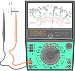
① Analog Multimeter Physical Image
A digital multimeter consists of the following parts: a liquid crystal display, a power switch, a transistor hFE socket, a rotary switch, and input jacks. The measurement results of a digital multimeter are displayed directly as numerical values.
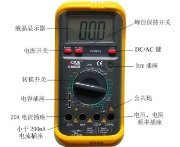
Digital Multimeter Physical Image
Multimeters have multi-function and multi-range measurement capabilities and can generally measure direct current, direct voltage, alternating current, alternating voltage, resistance, and audio levels. Some can also measure capacitance, inductance, and parameters of semiconductor devices.
Precautions:
1. Before measuring, check whether the positions of the red and black probes are correct. The red probe should be connected to the red terminal or the socket marked with “+”, and the black probe should be connected to the black terminal or the socket marked with “-“. They must not be reversed; otherwise, when measuring direct current, reversing the positive and negative leads will cause the pointer to reverse, damaging the meter head components.
2. Before connecting the probes to the circuit being measured, be sure to check whether the selected range matches the measurement object; otherwise, using the wrong range and setting will not only yield no results but may also damage the multimeter.
3. During measurement, hold both probes with your right hand, and avoid touching the metal parts of the probes and the component being measured with your fingers.
4. If it is necessary to change the range during measurement, it must be done after the probes have been removed from the circuit; otherwise, the arc generated by turning the switch may damage the contacts of the rotary switch, causing poor contact accidents.
5. In practical measurements, it is often necessary to measure various electrical quantities, and before each measurement, pay attention to set the rotary switch to the appropriate range and setting based on the measurement task.
6. When measuring high voltage or large current, to avoid damaging the switch, the power supply should be turned off before changing the range.
7. When measuring unknown voltage or current, first select the highest range, and after reading the initial value, gradually switch to the appropriate position to obtain a more accurate reading and avoid damaging the circuit.
8. If a fuse blows due to overload, you can open the fuse cover and replace it with a spare fuse of the same model.
9. When measuring high voltage, stand on a dry insulating board and operate with one hand to prevent accidents.
10.It is strictly forbidden to measure voltage with the ohm setting and current setting; when measuring resistance in a circuit, make sure to disconnect the power first to prevent damage to the instrument due to voltage across the resistance being measured.
11. After using the analog multimeter, the rotary switch should be turned to the open position or the highest alternating voltage setting. Digital multimeters that are not used for a long time should have their batteries removed to prevent old batteries from leaking and corroding the battery contacts.
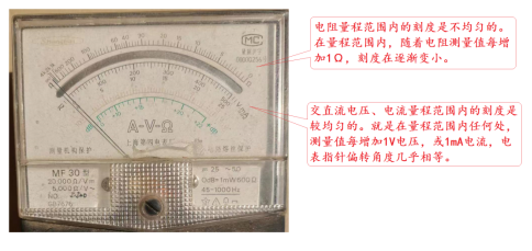
12. The first scale line on the surface of the multimeter (from top to bottom) is marked with Ω or R, which is used for measuring resistance. The characteristic is that the values are distributed non-linearly, and the left zero scale is the maximum value, as shown in the figure below.
13. When using an analog multimeter to measure diodes in the R×1kΩ ohm range, since the black probe is connected to the positive terminal of the internal battery, the black probe acts as the positive terminal of the power supply, while the red probe acts as the negative terminal. When the black probe is connected to the positive terminal of the diode and the red probe is connected to the negative terminal, the diode conducts forward, and the resistance value is about several hundred ohms. When the black probe is connected to the negative terminal of the diode and the red probe is connected to the positive terminal, the diode is reverse-biased, and the resistance value should be above several hundred kilo-ohms.
14. Devices that are not suitable for measurement using the multimeter’s resistance range:
a. When measuring resistance values, devices below 1 ohm are very difficult to distinguish.
b. The resistance of high-sensitivity microcurrent meter heads can be damaged by the current from the multimeter’s 1Ω range.
c. Measuring high-voltage insulation resistance with low-voltage power supply instruments cannot accurately reflect the insulation level of devices under high voltage.
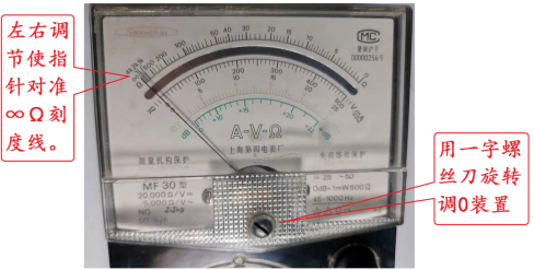
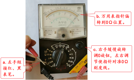
15. When measuring resistance values with an analog multimeter, mechanical zeroing (adjusting to ∞) and ohm zeroing (0Ω) should be performed before measurement. After each range change, ohm zeroing should be repeated before measuring resistance, as shown in the figure below.
Mechanical Zeroing: After placing the multimeter flat, use a flat screwdriver to rotate the zero adjustment device, adjusting left and right to align the pointer with the ∞Ω scale line.
Ohm Zeroing: a. Short-circuit the red and black probes with your left hand. b. The pointer of the multimeter should deflect to the 0Ω position. c. Slowly rotate the zero adjustment knob with your right hand, adjusting left and right to align the pointer with the 0Ω scale line.
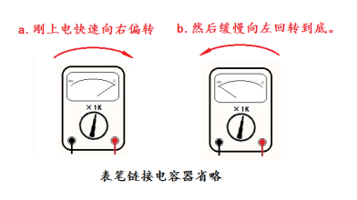
16. When measuring capacitance with an analog multimeter in the ohm range, the pointer movement can be divided into two processes:
a. At the moment the red and black probes connect to the capacitor terminals, the meter pointer deflects to the right to a certain position, at which point the meter’s internal battery charges the capacitor with maximum current.
b. Continuing to keep the probes connected to the capacitor, the meter pointer slowly returns to the left, and after a period, the pointer stabilizes near ∞Ω. This process occurs as the internal charge of the capacitor continues to increase, and the charging current gradually decreases until the capacitor is fully charged.
If the meter pointer does not deflect to the right after connecting the capacitor or does not return to near ∞Ω, it may indicate a problem with the capacitor, as shown in the figure below.
Appendix: Summary of Multimeter Knowledge Points and Exam Questions for Low-Voltage Electricians in Hefei
We are a one-stop certification service platform for low-voltage electricians. Currently, our service areas are Hefei and Shanghai, providing students with full-process services including registration, study, and examination. Our partner institutions are all certified training institutions recognized by the Emergency Management Bureau, with a pass rate of over 95% in recent years. At the same time, we offer various value-added services such as pre-exam simulations, on-site browsing of examination rooms, intensive courses before exams, and one-on-one tutoring to meet the needs of different types of students, helping you successfully obtain your certification.
If you have any questions about the low-voltage electrician certification, feel free to leave a message for consultation.
Scan to Consult
Scan to Follow