This article is approximately 4,000 words long; it is recommended to save it for reading.
Author | Zuo Chenggang
Produced by | Automotive Electronics and Software
Introduction:
This article is the thirteenth in the series of articles titled “Automotive Grade Testing of ECUs” (click to view all articles). EMC related knowledge, including standards and testing, is extensive. The previous articles have detailed all aspects of conducted emissions, radiated emissions, conducted immunity and radiated immunity -ALSE method. Currently, only the radiated immunity – Bulk Current Injection (BCI) and electrostatic discharge ( ESD ) immunity remain. The standard for radiated immunity is GB/T 33014, adopting the international standard ISO 11452. The previous articles introduced GB/T 33014.1 (General Provisions) and GB/T 33014.2 (Radiated Immunity -ALSE method). This article will continue to introduce another commonly used standard in this series GB/T 33014.4 Bulk Current Injection (BCI) method.
All test items in this article are accompanied by real DV test photos, including test equipment, samples, test setups, test limits, and result determinations, helping everyone gain a deeper understanding and recognition of DV testing. Special thanks to CVC Weikai Testing Technology for providing laboratory technical support and test photos..
*Note: Some content of this article is excerpted from the author’s new book “Reliability Design and Development Practice of General Automotive Grade Electronic Components“, published by the Machinery Industry Press in June 2024, with adaptations made during the excerpt. This article contains a lot of content, and it is recommended to save it for reading.The table of contents is as follows:
1. GB/T 33014.4 Bulk Current Injection (BCI) Method
1.1 General Provisions
1.2 Test Equipment and Test Arrangement Requirements
1.3 Test Arrangement
1.4 Test Method
1.5 Test Severity Levels and Frequency Bands
2. Radiated Immunity BCI Method DV Testing
2.1 DV Test Levels and Requirements
2.2 Radiated Immunity BCI Method DV Test Arrangement
2.3 Result Determination
#01
GB/T 33014.4 Bulk Current Injection (BCI ) Method
Here, I would like to correct an error from the previous article. The GB/T 33014 standard consists of a total of 10 parts, and the last standard GB/T 33014.11-2023 was omitted in the previous article. This standard was released later and will be implemented on 2024-04-01, being the last one in the GB/T 33014 series of standards. Except for the first part of the standard, which contains general provisions, the other nine standards specify different testing methods, but the commonly used ones are just two: Part 2: Anechoic Chamber Method (ALSE method) and Part 4: Bulk Current Injection Method (BCI). Below, we will detail the fourth part, the Bulk Current Injection Method (BCI method).
GB/T 33014.4-2016 is the current version of the standard, implemented on 2017-11-1, with the full name: Road Vehicles – Test Methods for the Immunity of Electrical/Electronic Components to Narrowband Radiated Electromagnetic Energy – Part 4: Bulk Current Injection (BCI) Method, adopting ISO 11452-4:2005, MOD.
1.1 General Provisions
The GB/T 33014.4 standard applies to electrical/electronic components for vehicles classified as M (passenger vehicles), N (cargo vehicles), O (trailers), and L (two-wheeled and three-wheeled vehicles), without limiting the vehicle power systems (fuel, hybrid, or electric vehicles). This is consistent with GB/T 33014.2. The difference is that the frequency range and current probe characteristics used in the Bulk Current Injection (BCI) method are related to 1MHz~400MHz, which is much lower than the frequency range of the ALSE method 80MHz~18000MHz; additionally, there are multiple types of current probes, which should be noted.
Test temperature, test voltage, modulation method, dwell time, frequency step size, and definitions of test severity levels are executed according to the provisions of GB/T 33014.1. Furthermore, the standard requires that tests be conducted in a shielded room, while the ALSE method is conducted in an anechoic chamber.
1.2 Test Equipment and Test Arrangement Requirements
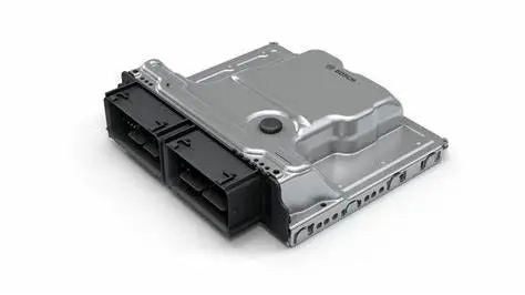
The Bulk Current Injection (BCI) method is a method of conducting immunity tests by directly coupling disturbance signals into the wiring harness using a current injection probe. Here, have you noticed that this method is quite similar to the current probe method in conducted emissions that we discussed earlier? The current probe method measures the conducted emissions across the entire wiring harness of the DUT, while here, the current probe is used to conduct immunity testing on the DUT through the wiring harness. Isn’t it somewhat analogous? The interference and immunity are two sides of the same product’s EMC performance.
The injection probe is a current transformer, and the wiring harness of the Device Under Test (DUT) passes through the current probe. This test setup is the same as that for conducted emissions testing, where the test is conducted by varying the test severity level and the frequency of the induced disturbance.
The test equipment for the radiated immunity BCI method includes:
-
Current injection probe (probe set): Coupling the output signal of the test equipment to the DUT, the probe set can withstand continuous input power across the entire frequency range.
-
Current measurement probe (probe set): Should cover the entire frequency range.
-
Artificial Network (AN)
-
RF signal generator: Capable of internal or external modulation.
-
Power amplifier
-
Power meter (or equivalent measuring instrument): Used to measure forward and reflected power.
-
Current measurement device
In terms of test arrangement, the grounding plate should be made of at least 0.5mm thick copper, brass, or galvanized steel plate. The minimum width should be 1000mm, and the minimum length should be 2000mm, or larger than each side of the entire equipment by 200mm, taking the larger of the two dimensions. The height of the grounding plate (test bench) should be positioned above the ground at (900±100)mm, and the grounding plate should be electrically connected to the shielded room shell. The distance between grounding strips should not exceed 300mm, and the DC resistance should not exceed 2.5mΩ. These test arrangement requirements are completely consistent with those in GB/T 33014.2 (ALSE method).
Additionally, each power line of the DUT should pass through 5μH/50Ω AN connected to the power supply. Typically, the negative of the power supply is grounded. If the power supply used by the DUT is positively grounded, the test arrangement specified by the standard needs to be adjusted accordingly. These requirements are consistent with the ALSE method. Furthermore, the number of required ANs is determined based on the installation of the DUT in the vehicle. The AN should be directly installed on the grounding plate, and the shell should be connected to the grounding plate. The power return line should be connected to the grounding plate (between the power supply and the AN), and each AN’s measurement port should connect to a 50Ω load.
Similar to the ALSE method, the number of ANs required also needs to be determined based on the installation of the DUT in the vehicle, as follows:
-
If the DUT is grounded at a distance (the vehicle power return line is greater than 200mm): Two ANs are required, one connected to the positive power supply and the other to the power return line.
-
If the DUT is grounded nearby (the vehicle power return line is not greater than 200mm): Use one AN, connected to the positive power supply.
Regarding the DUT, the following provisions apply:
-
The DUT should be placed on a non-conductive, low relative permittivity (Er ≤ 1.4) material, positioned above the grounding plate (50 ± 5)mm.
-
The shell of the DUT should not be connected to the grounding plate (except for simulating the actual vehicle structure).
-
The surface of the DUT should be at least 100mm away from the edge of the grounding plate. This provision is also basically consistent with emission testing.
-
In addition to the grounding plate on which the DUT is placed, the DUT and any other metal components (such as the walls of the shielded room) should be at least 500mm apart.
Regarding the wiring harness and simulated load, the following provisions apply:
-
The total length of the test wiring harness between the DUT and the load simulator should be (1000 ± 10)mm.
-
The test wiring harness should be placed on an insulating support, positioned above the grounding plate (50 ± 5)mm.
-
The test wiring harness should be placed in a straight line, with fixed positions and quantities.
-
The wiring harness should pass through the current injection probe and the current measurement probe.
-
The wires connecting the load simulator should be fixed, and their length should be shorter than that of the test wiring harness.
-
It is best to place the load simulator directly on the grounding plate, and if the load simulator has a metal shell, the shell should be directly connected to the grounding plate.
-
If the load simulator is placed on the grounding plate, the DC power line of the load simulator should be connected through the AN.
Regarding the distance between the current probe and the DUT connector, the following provisions apply:
-
d=(150 ± 10)mm
-
d=(450 ± 10)mm
-
d=(750 ± 10)mm
If a current measurement probe is used during testing, it should be located at the DUT connector (50 ± 10)mm away.
In contrast, the conducted emissions current probe method requires measurements at distances of 50mm and 750mm from the test item. Does this seem somewhat similar?
1.3 Test Arrangement
The standard specifies two types of test arrangements: substitution method and closed-loop method with power limitation. The substitution method test arrangement is shown in the figure below:
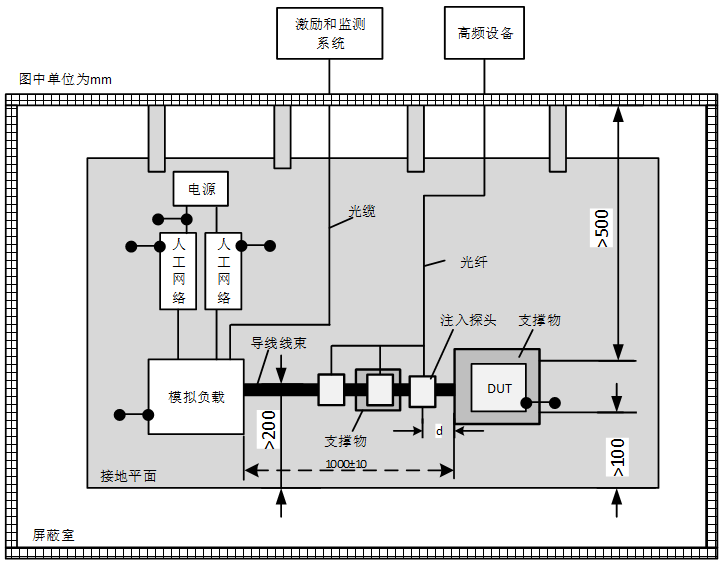
Radiated Immunity: BCI Method Test Arrangement Example– Substitution Method (Compiled by: Zuo Chenggang)
In the closed-loop method with power limitation, the current injection probe should be placed at a distance of (900 ± 10)mm from the DUT connector, and the current measurement probe should be placed at a distance of (50 ± 10)mm from the DUT connector. The test arrangement example for the closed-loop method with power limitation is shown in the figure below.
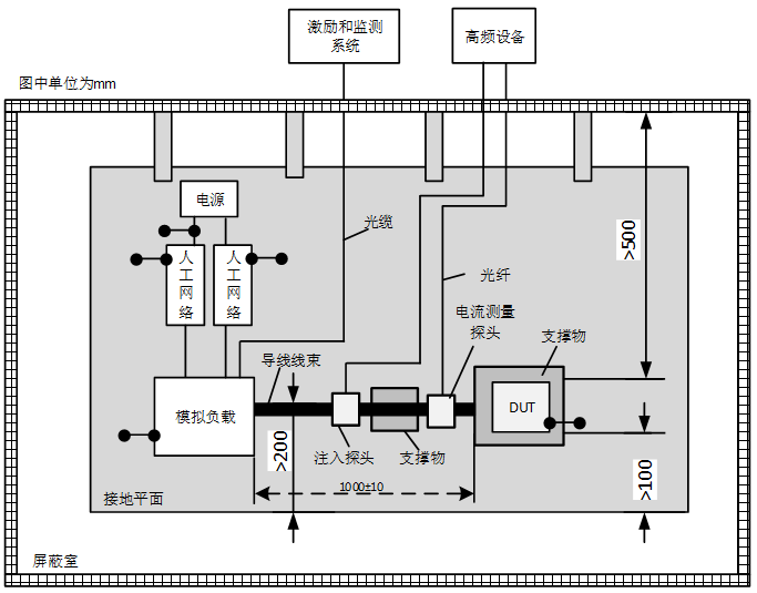
Radiated Immunity: BCI Method Test Arrangement Example– Closed-loop Method with Power Limitation (Compiled by: Zuo Chenggang)
From the above two test arrangements, it can be seen that the overall arrangement is basically the same as that of the conducted emissions current probe method, with the difference being some probe distance requirements.
1.4 Test Method
Before conducting the test, a test plan should be developed, including the following content: test arrangement, test method, frequency range, operating mode, acceptance criteria, severity levels, DUT monitoring conditions, probe positions, and injection methods for wiring harnesses with multiple connectors. If the overall layout of the test deviates from the standard requirements, it must be approved before the test and recorded in the test report. The DUT should be connected to a typical load, and the operating conditions should be consistent with those in the vehicle. These operating conditions should be specified in the test plan to ensure that the supplier and customer conduct exactly the same test.
Additionally, whether using the substitution method or the closed-loop method with power limitation, the standard requires calibration of the specified current levels. The difference is that the substitution method requires periodic calibration, while the closed-loop method with power limitation requires calibration before actual testing. Specific calibration methods can be found in the standard appendix A, which will not be elaborated here.
1.5 Test Severity Levels and Frequency Bands
The standard provides recommended test severity levels and frequency bands in Appendix C, with severity levels based on the aforementioned functional state characteristics classification (FPSC). The severity levels are actually consistent with the ALSE method, except that the units of the test levels change from V/m to mA, as shown in the table below:
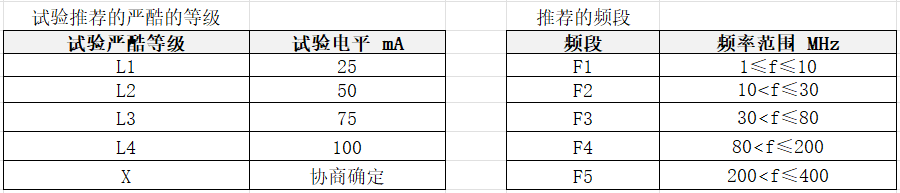
Recommended severity levels and frequency bands (Compiled by: Zuo Chenggang)
#02
Radiated Immunity BCI Method DV Testing
According to the standard requirements, the radiated immunity BCI method is conducted in a shielded room, as shown in the DV report below, with a test frequency range of 1MHz~400MHz, using the substitution method for testing.
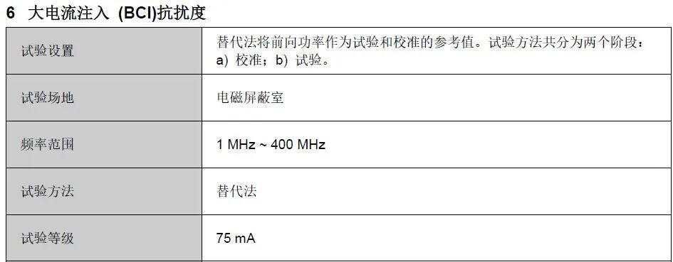
Testing conditions for the radiated immunity BCI method (Source: Fuqiao Diagram, CVC Weikai)
The facilities and equipment required for the radiated immunity testing will be listed in the DV report, as shown in the figure below:
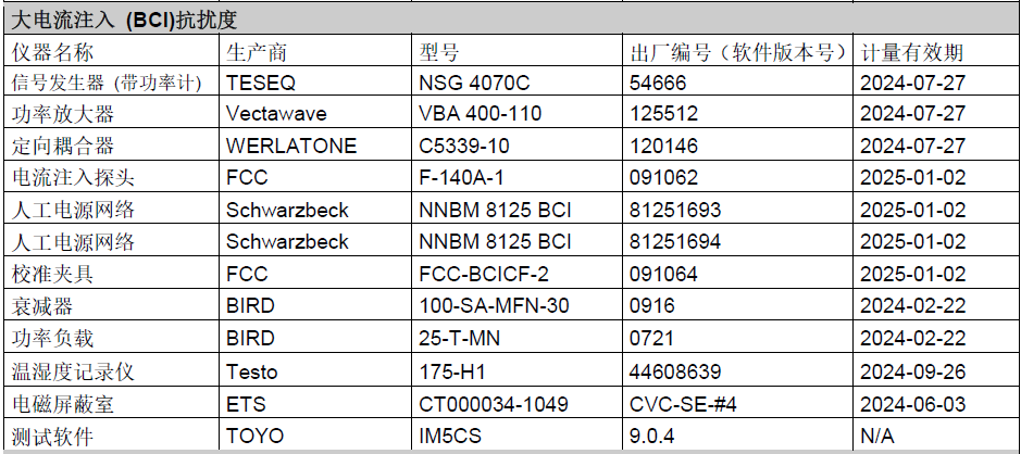
Radiated immunity test site and disturbance/ emission tests are similar, but the equipment used differs, such as the signal generator, power amplifier, directional coupler, current injection probe, artificial network, calibration fixture, etc. These are all used to couple disturbance signals into the DUT wiring harness through the current injection probe, thereby testing the DUT’s radiated immunity characteristics.
2.1 DV Test Levels and Requirements
In this DV test, the test levels, requirements, and determination criteria for the DUT are as follows:
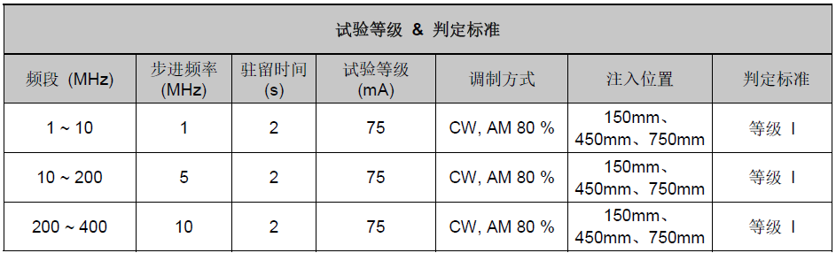
Radiated immunity BCI method test levels and determinations (Source: Fuqiao Diagram, CVC Weikai)
As seen in the figure, the DUT underwent testing in the frequency range of 1MHz~400MHz, with a test level of 75mA, and the step frequency and dwell time were also according to standard requirements. The test severity level was L3, just below L4 at 100mA. Additionally, the frequency bands from F2 to F4 were integrated into 10~200MHz, with injection positions tested at 150mm, 450mm, and 750mm respectively, with determination criteria requiring level I.
2.2 Radiated Immunity BCI Method DV Test Arrangement
According to standard requirements, the radiated immunity BCI method test arrangement and local arrangement are shown in the figure below. As seen in the figure, the DUT was tested at different positions:
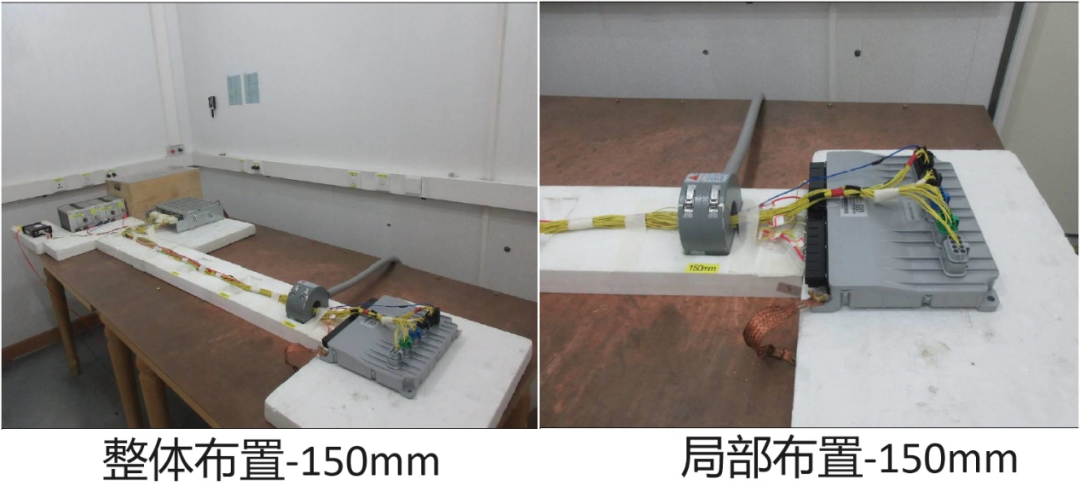
Radiated immunity BCI method test arrangement -150mm (Source: Fuqiao Diagram, CVC Weikai)
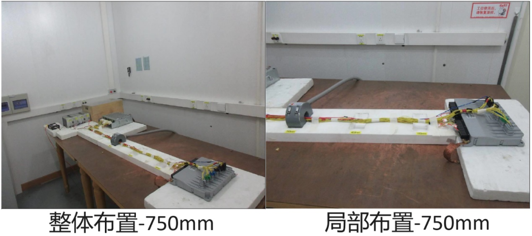
Radiated immunity BCI method test arrangement -450mm (Source: Fuqiao Diagram, CVC Weikai)
Radiated immunity BCI method test arrangement -750mm (Source: Fuqiao Diagram, CVC Weikai)
Radiated immunity BCI method local test arrangement (Source: Fuqiao Diagram, CVC Weikai)
As seen in the figure, the test arrangement follows standard requirements, with the DUT powered through LISN, the DUT connected to a simulated load, and both the DUT and simulated load placed on insulating supports. The injection positions were tested at 150mm, 450mm, and 750mm respectively.
2.3 Result Determination
The determination of test results is shown in the figure below:
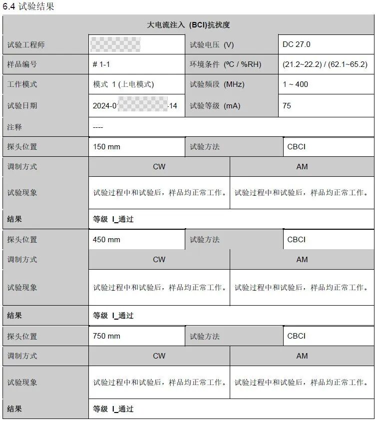
Test results and determinations (Source: Fuqiao Diagram, CVC Weikai)
As seen in the figure, the DUT’s operating mode during the test was mode 1, which is the operational mode, with a test voltage of DC27V (the DUT is a 24V system product), and the standard requires 27V± 1V, with modulation methods of CW and AM. For all test positions, during and after the test, the sample operated normally, meeting standard requirements, and all test results were ultimately classified as level I pass.
This article mainly introduces the radiated immunity standard GB/T 33014.4 (Bulk Current Injection BCI method). The GB/T 33014 standard consists of a total of 10 parts, all concerning radiated immunity. Except for the first part of the standard, the other 9 parts (2, 3, 4, 5, 7, 8, 9, 10, and 11) specify different testing methods. Thus, the commonly used radiated immunity standards: Anechoic Chamber ( ALSE method and Bulk Current Injection ( BCI) method have all been introduced. The next article will focus on electrostatic ( ESD ) immunity, stay tuned.
 / END /