
In today’s digital age, efficient computing is the core driving force behind technological development. The ARM and Linux interrupt systems serve as the key to unlocking this door to efficient computing. The ARM architecture, with its low power consumption and high performance characteristics, is widely used in various devices from smartphones to industrial control systems, laying a solid foundation for system operation. The Linux operating system, with its open-source and flexible advantages, has become the first choice for many developers.
So, what role does the interrupt system play in this? Simply put, the interrupt system acts like a smart steward, quickly notifying the CPU to pause its current task when external devices (such as keyboards and mice) or internal events (such as timer overflows) have service requests, allowing the CPU to handle urgent matters and then cleverly return to its original work. This mechanism greatly enhances the system’s response speed and operational efficiency. Especially in the combination of ARM and Linux, the interrupt system has been deeply optimized to further tap into the potential of both. In the following content, we will delve into the working principles and technical details of the ARM+Linux interrupt system, exploring how it empowers efficient computing.
1. The Interrupt System: The “Emergency Responder” of the Computing World
In daily life, we inevitably encounter various emergencies. When a fire occurs, a smoke detector instantly senses the anomaly and emits a sharp alarm. This alarm acts like sending an “emergency signal” to the firefighting system, prompting firefighters to immediately stop their current work, rush to the fire scene, and begin firefighting operations until the fire is extinguished, after which they return to the fire station, ready for the next task. Similarly, on busy roads, if a serious traffic accident occurs, the injured urgently need medical attention.
At this time, a bystander will immediately call the emergency number 120. Upon receiving the call, the emergency center will dispatch an ambulance, and medical personnel will quickly leave their current tasks to rush to the accident site to provide emergency treatment to the injured, and after transporting the injured to the hospital, they will return to their posts, ready to respond to the next emergency need.
In the world of computers, there exists a similar “emergency response mechanism”, which is the interrupt system. The CPU of a computer is like the firefighters or medical personnel, executing various program tasks in an orderly manner. When external devices (such as keyboards, mice, network cards, etc.) or internal events (such as timer overflows) require urgent attention from the CPU, they send interrupt signals to the CPU. Upon receiving the interrupt signal, the CPU temporarily halts its current task to handle the interrupt request. After processing the interrupt, it returns to the interrupted task and continues executing subsequent instructions.
The ARM+Linux interrupt system is based on the combination of the ARM architecture hardware platform and the Linux operating system’s interrupt handling system. The ARM architecture, with its low power consumption, high performance, and rich peripheral interfaces, is widely used in embedded fields, from smartphones and tablets to industrial control devices and smart home systems. The Linux operating system, favored by developers for its open-source, stability, and strong customizability, occupies an important position in the server field and is also widely adopted in embedded system development. The efficient operation of the ARM+Linux interrupt system is crucial for ensuring the stable operation and real-time response of these devices and systems, making it key to understanding and developing applications based on the ARM+Linux platform.
2. The Hardware Foundation of ARM Interrupts
2.1 ARM Operating Modes and Exception Categories
The ARM processor has seven operating modes, akin to a versatile actor who can switch roles based on different scenarios. Each mode has its unique purpose and privileges, working together to maintain the stable operation of the system.
- User Mode: This is the mode in which user programs normally execute, similar to ordinary citizens operating within their living space, with relatively limited privileges. In this mode, programs can only execute their data processing tasks and cannot arbitrarily manipulate other hardware resources or directly switch to other modes. For example, various apps running on our smartphones mostly operate in user mode, restricted by the system to prevent arbitrary access to lower-level hardware, ensuring system security and stability.
- System Mode: This is a privileged mode, akin to city managers. Although it shares a set of registers with user mode, it has higher privileges and can freely access system resources without the restrictions of user mode. Some privileged tasks of the operating system utilize this mode to access controlled resources, such as reading and writing critical system files.
- Interrupt Mode (IRQ Mode): This mode is used to handle general interrupt requests. When hardware generates an interrupt signal, it automatically enters this mode, similar to a city’s ordinary emergency response department, always ready to handle various routine emergencies. For instance, interrupts generated by keyboard key presses or mouse movements are handled by interrupt mode.
- Fast Interrupt Mode (FIQ Mode): This mode is primarily used to handle time-critical interrupt requests, like a special emergency response team in a city, playing a key role in high-speed data transmission and channel processing scenarios. For example, during real-time transmission of audio and video data, interrupts related to ensure data smoothness and timeliness are handled by fast interrupt mode. It is faster than the ordinary interrupt mode because it has more independent registers (r8 – r14 and SPSR have corresponding banked registers), and during mode switching, the CPU automatically saves and restores these register values without manual operation by the interrupt handler, saving time. Moreover, its entry address (0x1c) differs from that of ordinary interrupts (0x18), reducing the number of jump instructions due to jump range limitations, thus improving processing speed.
- Supervisor Mode: This is the default mode after the CPU is powered on, serving as the operating system’s protection mode, where the soft interrupt (SWI) handling function executes. It is like the highest management decision-making level in a city. When a program in user mode requests to use hardware resources, it enters this mode through a software interrupt. For instance, when a user program needs to read a disk file, it triggers a soft interrupt to enter supervisor mode, where the operating system performs the specific disk read operation. The system reset or power-on also enters this mode, typically performing system initialization tasks here.
- Data Abort Mode: This mode is entered when a program accesses an illegal address or a memory address it does not have permission to read, similar to a city’s security inspection department intervening when illegal access is detected. The segment fault error often encountered in Linux programming is usually thrown in this mode. For example, if a program attempts to access a memory area not allocated to it, it triggers a data access abort exception and enters this mode.
- Undefined Mode: This mode is entered when the CPU cannot recognize the instruction operation during the instruction decoding phase, used to support software emulation of hardware coprocessors, like a city’s exploratory research department for unknown situations. For instance, executing a specific floating-point operation instruction on hardware that does not support it will enter undefined mode.
Among these seven modes, except for user mode, the other six modes are privileged modes with higher privileges, allowing access to all system resources and the ability to freely switch processor modes. Among the privileged modes, except for system mode, the other five modes (interrupt mode, fast interrupt mode, supervisor mode, data abort mode, and undefined mode) are collectively referred to as exception modes, which can be triggered by specific exceptions as well as switched into by privileged programs.
Interrupt mode is one of the ARM exception modes (IRQ mode, FIQ mode), representing an asynchronous event, such as interrupts generated by external keys, internal timers, or communication data ports.
When an exception occurs, taking FIQ as an example, when the CPU enters FIQ mode:
- ① The address of the next instruction of the original executing program is saved to LR, which means saving R14 to R14_fiq.
- ② Copy CPSR to SPSR_fiq.
- ③ Change the CPSR mode bit value to FIQ mode.
- ④ Change the PC value to point to the corresponding exception handling vector table.
When exiting exception handling:
- ① Assign LR (R14_fiq) to PC.
- ② Copy SPSR (SPSR_fiq) to CPSR.
- ③ Clear the interrupt disable flag (if it was set initially).
When an external IRQ interrupt occurs:
- ① The processor switches to IRQ mode.
- ② The PC jumps to 0x18 to run, as this is the IRQ interrupt entry.
- ③ Through 0x18: LDR PC, IRQ_ADDR, jump to the corresponding interrupt service routine. This interrupt service routine must determine the interrupt source, as each interrupt source will have its own independent interrupt service routine.
- ④ Identify the interrupt source and then execute the corresponding interrupt service routine.
- ⑤ Clear the interrupt flag and return.
This is the complete execution flow of an external interrupt. Next, we will delve into the ARM interrupt mechanism with specific registers.
Assuming the ARM core has two interrupt pins, one is the irq pin and the other is the fiq pin. Under normal circumstances, the ARM core mechanically executes according to the PC indication. When both the I and F bits in CPSR are set to 1, both IRQ and FIQ are disabled, and at this time, regardless of the signal sent, the ARM will not respond.
When either the I or F bit is set to 0, and an interrupt signal comes from the irq pin, the current work of the ARM will be interrupted, switching to IRQ mode, and jumping to the interrupt entry at the exception vector table at 0x18. The corresponding bit in SRCPND is set to 1, and after checking the interrupt priority register and mask register, the interrupt source is determined, with the corresponding bit in INTPND set to 1 (after arbitration, only one bit is set to 1). This process is automatically completed by the ARM. 0x18 stores the general interrupt handler function, where a secondary interrupt vector table can be established. First, clear the corresponding bit in SRCPND, then execute the corresponding interrupt service routine based on the interrupt source, clear INTPND, and return.
Timely clearing the interrupt Pending register’s flag is to avoid two issues: ① being interrupted again immediately after returning from an interrupt, causing repeated responses; ② losing interrupts that occur during the interrupt handling process, resulting in no response after returning.
During the execution of a certain IRQ interrupt program, if another external IRQ interrupt occurs, it will set the corresponding bit in SRCPND to 1. After the interrupt service is completed, arbitration will determine the next interrupt to respond to. However, if a FIQ occurs, the current IRQ context will be saved, and the FIQ will be nested. After the FIQ service program is executed, the IRQ service will continue. So, what happens if another FIQ occurs while a FIQ is being serviced? The answer is that it will not be interrupted; like IRQ, it will wait until the current interrupt service is completed before arbitrating the remaining interrupts that need to be responded to.
Thus, we conclude:
- ① Regarding interrupt nesting: IRQ mode can only be interrupted by FIQ mode; no one can interrupt in FIQ mode.
- ② Regarding priority: The ARM core has clear programmable management of interrupt priorities.
Next, let’s see how Linux handles ARM interrupts, keeping in mind one premise: Linux can choose to take or leave ARM’s hardware features, but cannot change them.
Establishing the exception vector table: The system starts executing from arch/arm/kernel/head.S’s ENTRY(stext), __lookup_processor_type checks the processor ID, __lookup_machine_type checks the machine ID, __create_page_tables creates page tables, starts the MMU, and then jumps from arch/arm/kernel/head_common.S to start_kernel()->trap_init()
void __init trap_init(void)
{
    unsigned long vectors = CONFIG_VECTORS_BASE;
    …
    memcpy((void *)vectors, __vectors_start, __vectors_end - __vectors_start);
    memcpy((void *)vectors + 0x200, __stubs_start, __stubs_end - __stubs_start);
    memcpy((void *)vectors + 0x1000 - kuser_sz, __kuser_helper_start, kuser_sz);
    …
}
#define CONFIG_VECTORS_BASE 0xffff0000
CONFIG_VECTORS_BASE is defined in autoconf.h. In most processors after ARM V4 and V4T, the interrupt vector table can be located in two places: one is 0, and the other is 0xffff0000. This can be controlled by the V bit (bit[13]) in the CP15 coprocessor c1 register. The relationship between V and the interrupt vector table is as follows:
V=0 ~ 0x00000000~0x0000001C
V=1 ~ 0xffff0000~0xffff001C
__vectors_end to __vectors_start contains the exception vector table, located in arch/arm/kernel/entry-armv.S
.globl __vectors_start
__vectors_start:
    swi SYS_ERROR0
    b vector_und + stubs_offset // Reset exception
    ldr pc, .LCvswi + stubs_offset // Undefined exception
    b vector_pabt + stubs_offset // Software interrupt exception
    b vector_dabt + stubs_offset // Data exception
    b vector_addrexcptn + stubs_offset // Reserved
    b vector_irq + stubs_offset // General interrupt exception
    b vector_fiq + stubs_offset // Fast interrupt exception
.globl __vectors_end
__vectors_end:
The stubs_offset value is as follows:
.equ stubs_offset, __vectors_start + 0x200 - __stubs_startHow is stubs_offset determined?
When the assembler sees the B instruction, it converts the label to be jumped to into an offset relative to the current PC (±32M) written into the instruction code. From the above code, we can see that both the interrupt vector table and stubs have undergone code relocation, so if the interrupt vector table still writes b vector_irq, then during actual execution, it cannot jump to the relocated vector_irq location because the instruction code writes the original offset. Therefore, we need to write the offset in the instruction code to the relocated one. We denote the entry address of the interrupt in the interrupt vector table as irq_PC, and its offset in the interrupt vector table is irq_PC-vectors_start, while vector_irq’s offset in stubs is vector_irq-stubs_start. These two offsets remain unchanged before and after relocation.
After relocation, vectors_start is at 0xffff0000, while stubs_start is at 0xffff0200, so the relocated vector_irq’s offset relative to the interrupt entry address in the interrupt vector table is 200 + vector_irq in stubs’ offset minus the interrupt entry in the vector table, i.e., 200 + vector_irq-stubs_start-irq_PC+vectors_start = (vector_irq-irq_PC) + vectors_start+200-stubs_start. The value in parentheses is actually the vector_irq written in the interrupt vector table, and subtracting irq_PC is done by the assembler, while the latter part vectors_start+200-stubs_start should be defined as stubs_offset in entry-armv.S.
2.2 ARM Interrupt Pins and Interrupt Enable Control
In the ARM architecture, the hardware implementation of interrupts relies on specific pins and control mechanisms. We can assume that the ARM core has two interrupt pins (actually integrated within the chip and not visible externally), one called irq pin for general interrupt requests, and the other called fiq pin for fast interrupt requests. These two pins act like “emergency contact lines” connecting external devices to the CPU. Once an external device has urgent matters requiring CPU processing, it sends interrupt signals to the CPU through these two pins.
Whether the CPU responds to these interrupt signals is controlled by the current Program Status Register (CPSR), specifically the I and F bits. When the I bit in CPSR is set to 1, IRQ interrupts are disabled, meaning that even if there is an interrupt signal on the irq pin, the CPU will not respond, just like a firefighter silencing the fire alarm and ignoring the fire alert; when the F bit is set to 1, FIQ interrupts are disabled, and the interrupt signal on the fiq pin will also not attract the CPU’s attention. Only when both the I and F bits are set to 0 can the interrupt signals on the irq pin and fiq pin successfully interrupt the CPU’s current task, causing the CPU to switch to the corresponding interrupt mode for processing. For example, during critical operations that cannot be interrupted, the I and F bits in CPSR can be set to disable interrupts, ensuring the integrity and correctness of the operation.
When an external interrupt occurs, it jumps to the exception vector table’s “b vector_irq + stubs_offset // General interrupt exception”, entering the exception handling function. The entry position in arch\arm\kernel\entry-armv.S is briefly as follows:
.globl __stubs_start
__stubs_start:
/*
* Interrupt dispatcher
*/
vect... (truncated for brevity)
vector_stub is a function call macro that determines whether to enter __irq_usr or __irq_svc based on the working mode before the interrupt. Here, it enters __irq_svc, and we see that when FIQ occurs, the system does not perform any processing and directly returns, indicating that Linux does not provide support for FIQ. Continuing with the code:
__irq_svc:
svc_entry
…
irq_handler
svc_entry is a macro that primarily saves the registers and interrupt return address in SVC mode to the stack. Then it enters the core interrupt response function irq_handler, whose implementation process is in arch\arm\kernel\entry-armv.S:
.macro irq_handler
get_irqnr_preamble r5, lr
1: get_irqnr_and_base r0, r6, r5, lr @ Determine interrupt number, returned through R0, implementation process in section 3.5
movne r1, sp
@
@ routine called with r0 = irq number, r1 = struct pt_regs *
@
adrne lr, 1b
bne asm_do_IRQ @ Enter interrupt handling.
……
.endm
get_irqnr_and_base’s interrupt number determination process is in include/asm/arch-s3c2410/entry-macro.s:
.macro get_irqnr_and_base, irqnr, irqstat, base, tmp
mov \base, #S3C24XX_VA_IRQ
@@ try the interrupt offset register, since it is there
ldr \irqstat, [ \base, #INTPND ]
teq \irqstat, #0
beq 1002f
ldr \irqnr, [ \base, #INTOFFSET ] @ Get interrupt position by checking INTOFFSET register
…
@@ we have the value
1001:
adds \irqnr, \irqnr, #IRQ_EINT0 @ Add the base value of the interrupt number to get the final interrupt number, note: at this point, the specific situation of sub-interrupts is not considered. IRQ_EINT0 is defined in include/asm/arch-s3c2410/irqs.h. From this, we can see that the specific value of the interrupt number is determined by platform-related code and is not equal to the interrupt number in the hardware interrupt pending register.
1002:
@@ exit here, Z flag unset if IRQ
.endm
asm_do_IRQ’s implementation process is in arch/arm/kernel/irq.c:
asmlinkage void asm_do_IRQ(unsigned int irq, struct pt_regs *regs)
{
    struct pt_regs *old_regs = set_irq_regs(regs);
    struct irq_desc *desc = irq_desc + irq; // Find the corresponding irq_desc based on the interrupt number

    /*
     * Some hardware gives randomly wrong interrupts. Rather
     * than crashing, do something sensible.
     */
    if (irq >= NR_IRQS)
        desc = &bad_irq_desc;

    irq_enter();

    desc_handle_irq(irq, desc); // Enter interrupt handling based on irq and desc

    /* AT91 specific workaround */
    irq_finish(irq);

    irq_exit();
    set_irq_regs(old_regs);
}
static inline void desc_handle_irq(unsigned int irq, struct irq_desc *desc)
{
    desc->handle_irq(irq, desc); // Interrupt handling
}
The above asmlinkage void __exception asm_do_IRQ(unsigned int irq, struct pt_regs *regs) uses the asmlinkage identifier. So how should this identifier be understood?
This symbol is defined in kernel/include/linux/linkage.h as follows:
include//各个具体处理器在此文件中定义asmlinkage
#ifdef __cplusplus
        #define CPP_ASMLINKAGE extern "C"
        #else
        #define CPP_ASMLINKAGE
        #endif
#ifndef asmlinkage//如果以前没有定义asmlinkage
        #define asmlinkage CPP_ASMLINKAGE
        #endif
For ARM processors, asmlinkage is not defined, so it has no meaning (do not think that parameters are passed from the stack; for ARM platforms, they still conform to the ATPCS calling standard, passed through registers).
However, for x86 processors, it is defined as follows:
#define asmlinkage CPP_ASMLINKAGE __attribute__((regparm(0)))This indicates that the function’s parameters are passed via the stack.
Now that we have reached the interrupt handling process code, the last question is how desc->handle_irq(irq, desc); is related to the interrupt function we registered. Let’s start with the interrupt model registration:
Interrupt-related data structures are defined in include/asm/arch/irq.h:
irq_desc[] is an array pointing to irq_desc_t structures, and the irq_desc_t structure is a descriptor for each device’s interrupt service routine. The member action in the irq_desc_t structure points to the irqaction structure list corresponding to the interrupt number. The irqaction structure is defined in include/linux/interrupt.h as follows:
struct irqaction {
    irq_handler_t handler; // Interrupt handling function, provided during registration
    unsigned long flags; // Interrupt flags, provided during registration
    cpumask_t mask; // Interrupt mask
    const char *name; // Interrupt name
    void *dev_id; // Device id, this parameter's role will be detailed later in interrupt sharing
    struct irqaction *next; // If there is interrupt sharing, continue execution,
    int irq; // Interrupt number, provided during registration
    struct proc_dir_entry *dir; // Pointer to the descriptor of the /proc/irq/n directory related to IRQn
};
When registering an interrupt service program for the interrupt number irq, the system encapsulates the corresponding irqaction structure based on the registration parameters and writes the irqaction structure for interrupt number irq into irq_desc[irq]->action. This links the device’s interrupt request number with the corresponding irqaction interrupt service routine. When the CPU receives an interrupt request, it can find the device’s interrupt service program based on the interrupt number through irq_desc[].
2.3 Interrupt Vector Table and Interrupt Execution Flow
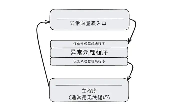
The interrupt vector table plays a crucial role in the ARM interrupt system, serving as the “navigation map” for interrupt handling. In 32-bit ARM systems, the interrupt vector table is generally located at specific memory addresses, with two optional locations: one is the low address 0x00000000 – 0x0000001c (Low vector); the other is the high address 0Xffff0000 – 0xffff001c (High vector), with the specific location determined by the CPU. The interrupt vector table stores the entry addresses of the handling programs corresponding to various interrupts and exceptions. When an interrupt or exception occurs, the CPU automatically points the program counter (PC) to the corresponding address in the interrupt vector table, thus jumping to the corresponding interrupt service routine for processing.
Taking external IRQ interrupts as an example, when an interrupt signal arrives on the irq pin, the entire interrupt execution flow is as follows:
- Mode Switching: When the ARM core detects an interrupt signal on the irq pin, it first checks the I bit in CPSR. If the I bit is 0 (indicating IRQ interrupts are not disabled), the CPU automatically switches to IRQ mode, just like a firefighter receiving a fire alarm and quickly changing into firefighting gear to enter combat mode.
- Jump to the Interrupt Vector Table: After switching to IRQ mode, the PC jumps to the entry address 0x18 corresponding to IRQ in the interrupt vector table. This process is automatically completed by hardware, like a firefighting system automatically guiding firefighters to the corresponding fire scene based on the type of alarm.
- Jump to the Interrupt Service Program: At address 0x18, there is usually a jump instruction (such as LDR PC, IRQ_ADDR). Through this instruction, the CPU jumps to the specific interrupt service program. The task of this interrupt service program is to determine the interrupt source, as multiple external devices may share the irq pin, and each device’s interrupt needs to be handled independently. For example, both the keyboard and mouse may send interrupt signals through the irq pin, and the interrupt service program needs to determine whether the interrupt was generated by a key press or mouse movement, and then execute the corresponding handling operation.
- Execute the Interrupt Service Program: After identifying the interrupt source, the CPU executes the corresponding interrupt service program to complete the handling of the interrupt event. For instance, if it is a keyboard interrupt, the interrupt service program may read the character input from the keyboard and pass it to the corresponding application; if it is a timer interrupt, it may update the system time or trigger scheduled tasks.
- Clear the Interrupt Flag and Return: After the interrupt service program is completed, the interrupt flag needs to be cleared to notify the system that the interrupt has been handled. Then, the CPU restores to the state before the interrupt, returning the program execution flow to the interrupted point to continue execution, just like firefighters removing their gear after extinguishing a fire and returning to their original work position to continue their unfinished tasks. In this process, the previously saved register values need to be restored, CPSR needs to be restored from SPSR, and the value in LR needs to be assigned to PC, ensuring that the program can seamlessly continue execution.
3. Basic Analysis of the ARM+Linux Interrupt System
3.1 ARM Architecture Interrupt Mechanism
In the brilliant starry sky of the ARM architecture, the interrupt mechanism is like a dazzling galaxy that connects the processor with external devices, providing crucial support for the efficient operation of the system. Interrupts under the ARM architecture can be mainly divided into two categories based on their characteristics and application scenarios: IRQ (Interrupt Request, external interrupt request) and FIQ (Fast Interrupt Request, fast interrupt request), each with its unique features and roles in different scenarios.
IRQ, as the representative of general interrupt requests, is a more common type of interrupt in the ARM architecture. When external devices such as keyboards, mice, and network interfaces have events that require the processor’s attention, they issue IRQ interrupt requests. It acts like a diligent messenger, frequently shuttling through the system, conveying various requests from external devices to the processor. In our daily use of smartphones, when a user taps the screen, the touch screen controller generates an IRQ interrupt, notifying the processor to perform the corresponding action, such as opening an application or scrolling a page. The characteristics of IRQ interrupts are strong versatility, capable of flexibly responding to various external device requests, like a universal interface connecting various external devices. Moreover, it can handle concurrent situations of multiple interrupt requests; when multiple external devices issue interrupt requests simultaneously, IRQ can orderly convey these requests to the processor, allowing the processor to handle them in a certain priority order, thus ensuring the system’s real-time performance and reliability.
On the other hand, FIQ is known as the “Flash Lightning” of the interrupt world, renowned for its rapid response characteristics. It is primarily used to handle interrupt requests that are extremely time-sensitive and require quick responses, such as high-speed data transmission and channel processing scenarios. In high-speed network communication, the reception and transmission of data need to be processed promptly; otherwise, it may lead to data loss or delays. At this time, FIQ plays an important role, as it can respond to interrupt requests in a very short time, quickly processing data to ensure smooth network communication. The reason FIQ can respond so quickly is due to its higher priority.
When both FIQ and IRQ occur simultaneously, the processor will prioritize responding to the FIQ interrupt without hesitation, just as in emergencies, people prioritize handling the most urgent matters. Additionally, the FIQ mode provides more banked registers, which are like a “fast track” tailored for FIQ. During mode switching, the CPU can automatically save and restore the values of the relevant registers, significantly reducing the overhead of context switching, thus improving the speed of interrupt handling.
In practical applications, we need to reasonably choose between using IRQ and FIQ based on different scenario requirements. For ordinary external devices with relatively low real-time requirements, such as printers and cameras, using IRQ interrupts is sufficient; while for high-speed data transmission devices with extremely high time requirements, such as high-speed USB interfaces and Ethernet controllers, FIQ interrupts should be used to ensure system performance.
3.2 Linux Management of ARM Interrupts
The Linux kernel, like a wise commander, manages ARM interrupts in an orderly manner to ensure the stable operation of the system. In this process, establishing the interrupt vector table and registering interrupts are two key steps, serving as the two “sharp blades” of Linux kernel management of ARM interrupts, playing a crucial role.
The interrupt vector table is the “navigation map” for interrupt handling, recording the entry addresses of each interrupt’s corresponding handling program. In the ARM architecture, the location of the interrupt vector table can be set through the control register C1 of the CP15 coprocessor. When this bit is 0, the interrupt vector table starts at 0x00000000; when it is 1, it starts at 0xffff0000. During the Linux kernel’s startup process, the interrupt vector table is meticulously established. It first determines the base address of the interrupt vector table, then copies the exception vector table from a specific location in memory to the base address of the interrupt vector table. The exception vector table contains the handling entries for various interrupts and exceptions, such as reset exceptions, undefined instruction exceptions, interrupt exceptions, etc.
In the ARMv8 architecture, the process of establishing the interrupt vector table involves multiple steps, including initializing the interrupt controller, setting the base address of the interrupt vector table, and copying the exception vector table to the base address of the interrupt vector table. Through these steps, the Linux kernel lays a solid foundation for interrupt handling, enabling the processor to quickly find the corresponding handling program entry when receiving an interrupt request, just like finding the route to a destination on a map.
Interrupt registration is the process of binding the device’s interrupt handling function to the interrupt number, akin to finding the corresponding “expert” for each interrupt request. In the Linux kernel, device driver developers need to use the request_irq function to register interrupts. The prototype of this function is as follows:
int request_irq(unsigned int irq, irq_handler_t handler, unsigned long irqflags, const char *devname, void *dev_id);
Here, irq is the hardware interrupt number to be requested, serving as the device’s “exclusive number” for uniquely identifying an interrupt request; handler is the interrupt handling function registered with the system, which will be called to handle the interrupt when it occurs, serving as the core code for handling interrupts; irqflags are the attributes of interrupt handling, such as setting IRQF_DISABLED, indicating that the interrupt handler is a fast processing program that will mask all interrupts when called to ensure quick handling of the interrupt; setting IRQF_SHARED indicates that multiple devices can share this interrupt, which is very useful in resource-limited systems; devname is the name of the interrupt for easy identification and management in the system, like labeling each device; dev_id is used in interrupt sharing, generally set to the device’s device structure or NULL, used to distinguish different devices when sharing interrupts.
When the device driver successfully registers the interrupt by calling the request_irq function, the Linux kernel associates the interrupt handling function with the interrupt number and records it in the corresponding interrupt management data structure. When an interrupt occurs, the kernel can find the corresponding interrupt handling function based on the interrupt number and call it to handle the interrupt. In an embedded system with multiple GPIO devices, each GPIO device may generate interrupts. The device driver will register the corresponding interrupt handling function for each GPIO device’s interrupt number, allowing the kernel to accurately find the corresponding interrupt handling function when a GPIO device generates an interrupt, thus achieving efficient communication between the device and the system. Through interrupt registration, the Linux kernel implements fine management of interrupts, enabling the system to flexibly respond to various device interrupt requests.
4. Building Interrupts in Linux on ARM
4.1 Establishing and Setting the Exception Vector Table
During the startup process of the Linux system based on the ARM architecture, establishing the exception vector table is a key step, akin to building an emergency command center for the city, laying the foundation for subsequent interrupt handling.
The ARM architecture supports placing the exception vector table at two different memory locations, specifically controlled by bit [13] (the V bit) of the CP15 coprocessor C1 register. When V = 0, the exception vector table is located at low addresses 0x00000000 – 0x0000001c; when V = 1, the exception vector table is located at high addresses 0Xffff0000 – 0xffff001c. In most ARM V4 and V4T processors, the high address exception vector table is typically chosen.
During the Linux kernel startup, the start_kernel() function is the starting point for the entire kernel initialization, where the trap_init() (which may be early_trap_init() in some kernel versions) function is responsible for initializing the exception vector table. Taking the early_trap_init() function as an example, its internal implementation process is as follows:
void __init early_trap_init(void)
{
    unsigned long vectors = CONFIG_VECTORS_BASE;
    extern char __stubs_start[], __stubs_end[];
    extern char __vectors_start[], __vectors_end[];
    extern char __kuser_helper_start[], __kuser_helper_end[];
    int kuser_sz = __kuser_helper_end - __kuser_helper_start;

    /* Copy exception vector table, stubs, and kuser helpers to vector page */
    memcpy((void *)vectors, __vectors_start, __vectors_end - __vectors_start);
    memcpy((void *)vectors + 0x200, __stubs_start, __stubs_end - __stubs_start);
    memcpy((void *)vectors + 0x1000 - kuser_sz, __kuser_helper_start, kuser_sz);

    /* Copy signal return handling function to vector page */
    memcpy((void *)KERN_SIGRETURN_CODE, sigreturn_codes, sizeof(sigreturn_codes));

    /* Flush instruction cache to make these changes visible to instruction flow */
    flush_icache_range(vectors, vectors + PAGE_SIZE);

    /* Modify access permissions for the page occupied by the exception vector table */
    modify_domain(DOMAIN_USER, DOMAIN_CLIENT);
}
First, it obtains the value of CONFIG_VECTORS_BASE, which is usually set in the configuration file for each platform, such as in arch/arm/configs/s3c2410_defconfig, where CONFIG_VECTORS_BASE = 0xffff0000, specifying the target address for the exception vector table. Then, it uses the memcpy function to copy the exception vector table (the content between __vectors_end and __vectors_start defined in arch/arm/kernel/entry-armv.S) to the target address vectors.
Simultaneously, it copies the exception handling stubs (the content between __stubs_end and __stubs_start) to the location vectors + 0x200, and the kuser helpers to the location vectors + 0x1000 – kuser_sz. Next, it copies the signal return handling function to a specific location. After that, it calls the flush_icache_range function to flush the instruction cache, ensuring that the CPU can access the latest code. Finally, it uses the modify_domain function to change the access permissions for the page occupied by the exception vector table, ensuring that only the kernel mode can access this page, safeguarding system security.
In the arch/arm/kernel/entry-armv.S file, the specific content of the exception vector table is defined as follows:
.globl __vectors_start
__vectors_start:
    swi SYS_ERROR0
    b vector_und + stubs_offset   // Reset exception
    ldr pc, .LCvswi + stubs_offset   // Undefined instruction exception
    b vector_pabt + stubs_offset   // Software interrupt exception
    b vector_dabt + stubs_offset  // Data interrupt exception
    b vector_addrexcptn + stubs_offset
    b vector_irq + stubs_offset   // General interrupt exception
    b vector_fiq + stubs_offset  // Fast interrupt exception
.globl __vectors_end
__vectors_end:
Here, each type of exception corresponds to a specific jump instruction, for example, the general interrupt (IRQ) corresponds to b vector_irq + stubs_offset. The value of stubs_offset is defined by .equ stubs_offset, __vectors_start + 0x200 – __stubs_start, ensuring that the jump instruction can correctly jump to the relocated exception handling program location after the exception vector table and stubs have undergone code relocation. When an ARM processor encounters an exception, it jumps to the corresponding location in the exception vector table based on the exception type, and then jumps to the corresponding exception handling program for execution.
4.2 Analysis of the Interrupt Handling Function Flow
When a hardware interrupt is triggered, the entire interrupt handling process resembles a well-organized relay race, involving multiple key functions and operations, transitioning from hardware to software for processing.
Assuming an external device (such as a button) generates an interrupt signal, this signal is first received by the interrupt controller of the ARM chip. Taking a common ARM chip interrupt controller as an example, it performs preliminary processing of the interrupt signal, checking the interrupt mask register and interrupt priority register, etc., to determine whether to pass this interrupt signal to the CPU. If the interrupt is not masked and has sufficient priority, the interrupt controller sends an interrupt request signal to the CPU via the irq pin.
The CPU continuously checks for incoming interrupt signals while executing the current instruction. When it detects an interrupt signal on the irq pin, and the I bit in the current Program Status Register (CPSR) is 0 (indicating IRQ interrupts are not disabled), the CPU immediately responds. First, the CPU automatically switches to IRQ mode, which is a hardware-automated operation, just like a firefighter quickly switching to combat mode. Then, the program counter (PC) jumps to the entry address 0x18 corresponding to IRQ in the interrupt vector table. At address 0x18, there is a jump instruction (such as LDR PC, IRQ_ADDR). Through this instruction, the CPU jumps to the specific interrupt handling program.
In the Linux kernel, the entry for the interrupt handling program is vector_irq, defined in the arch/arm/kernel/entry-armv.S file. vector_irq first performs some context protection operations, saving the current register values to ensure that it can restore to the state before the interrupt handling is completed. Then, through a series of checks and jumps, it ultimately calls the irq_handler macro.
The irq_handler macro actually calls the handle_arch_irq function, which is the handling function registered during the initialization of the interrupt controller. The handle_arch_irq function may vary across different ARM platforms; for example, on platforms using the GIC (Generic Interrupt Controller), the handle_arch_irq function typically points to the gic_handle_irq function.
gic_handle_irq is the core processing function of the GIC interrupt controller, and its main workflow is as follows:
- Read the Interrupt Acknowledge Register: First, read the GIC’s interrupt acknowledge register (GIC_CPU_INTACK), which effectively acknowledges to the GIC that the CPU has received the interrupt signal. At the same time, this register returns a unique interrupt number used to identify the device that generated the interrupt.
- Process the Interrupt: Based on the returned interrupt number, find the corresponding interrupt handling function and call it for interrupt processing. During this process, further checks and handling of the interrupt source may be involved, such as reading the device’s status register to obtain the specific reason for the interrupt.
- Notify Interrupt Completion: After the interrupt handling is completed, an interrupt end signal needs to be sent to the GIC. This is achieved by writing to the GIC’s interrupt end register (GIC_CPU_EOI), informing the GIC that this interrupt has been handled, and the GIC can accept interrupt requests for this interrupt number again.
At the driver level, when a device driver registers, it uses the request_irq function to register the interrupt. For example:
int request_irq(unsigned int irq, irq_handler_t handler, unsigned long flags, const char *name, void *dev);Here, irq is the interrupt number, handler is the specific interrupt handling function, flags are used to specify the attributes of the interrupt (such as interrupt trigger mode, whether to share the interrupt, etc.), name is the name of the interrupt, and dev is the context data passed to the interrupt handling function. When a hardware interrupt occurs and goes through the above series of processing, it ultimately calls the interrupt handling function registered in the driver. In the interrupt handling function, the specific processing is performed based on the device’s needs, such as reading data from the device, updating the device’s status, etc. After processing is completed, the interrupt handling function returns an irqreturn_t type value to inform the system of the result of the interrupt handling.
After the interrupt handling function is executed, context restoration operations are performed, restoring the previously saved register values, restoring CPSR from SPSR, assigning the value in LR to PC, etc., allowing the CPU to return to the state before the interrupt and continue executing the interrupted task.
5. Analysis of the GIC Interrupt Controller in ARM
5.1 Basic Concepts and Versions of GIC
In the interrupt system of the ARM architecture, the GIC (Generic Interrupt Controller) plays a crucial role, serving as the “commander” of interrupt management. It acts like a traffic control center in a city, responsible for collecting, managing, and distributing interrupt signals from various external devices and internal events, ensuring that the CPU can orderly process these interrupt requests.
Currently, there are four versions of GIC, namely V1 to V4. Among them, V1 is the earliest version and has gradually been phased out and is no longer widely used; version V2 is more commonly used, supporting up to 8 ARM cores, commonly found in ARMv7-A architecture chips such as Cortex-A7, Cortex-A9, Cortex-A15, etc. In early smartphones and tablets, GIC V2-based interrupt control is often seen; versions V3 and V4 are mainly aimed at ARM64 server system architectures, supporting more ARM cores to meet the needs of large-scale data processing and multi-task concurrency, playing an important role in data centers and cloud computing.
For example, GIC-500 supports up to 128 CPU cores, requiring the ARM core to be of the ARMV8 instruction set (such as Cortex-A57) and conforming to the GIC architecture specification version 3. In practical applications, different chip manufacturers choose the appropriate version of GIC based on their product needs. For instance, some mid-range embedded devices may adopt GIC V2 to reduce costs while meeting basic interrupt handling needs, while high-end server chips may opt for GIC V3 or V4 to provide powerful interrupt management capabilities and high-performance computing support.
5.2 Types of Interrupt Input Signals for GIC
The interrupt input signals received by GIC are mainly divided into three types, each with its unique characteristics and application scenarios, akin to different types of emergency events requiring different responses.
- PPI (Private Peripheral Interrupt): This is a private interrupt for each CPU, just like each person having their exclusive emergency contact method. PPI supports up to 16 interrupts, with hardware interrupt numbers from ID16 to ID31. It is usually sent to a designated CPU, one application scenario being the local clock of the CPU, such as the tick interrupt for process scheduling. In a multi-core processor, each core has its independent PPI interrupt to handle specific peripheral events closely related to that core, ensuring that each core can efficiently handle its tasks without interference.
- SPI (Shared Peripheral Interrupt): SPI is a shared interrupt for all cores, coming from peripherals, similar to a public emergency help channel. It can support up to 988 peripheral interrupts, with hardware interrupt numbers from ID32 to ID1019. Common interrupts such as button interrupts and serial port interrupts can be processed by all cores, not limited to a specific core. In a smart home system, interrupt signals generated by multiple sensors (such as temperature sensors, humidity sensors, door/window sensors, etc.) can be sent to the CPU via SPI interrupts, allowing the CPU to process them uniformly for intelligent monitoring and control of the home environment.
5.3 GIC’s Working Mechanism and Register Functions
The working mechanism of GIC mainly relies on two key components: the Distributor and the CPU Interface Module, which work together to manage and process interrupts, like an efficient team, each playing an important role.
Distributor
The Distributor acts like a dispatcher in a traffic control center, responsible for collecting all interrupt sources, controlling the priority of each interrupt, and distributing interrupt events to the corresponding CPU interface. Its main tasks include:
- Global Interrupt Enable Control: Through the GIC_DIST_CTRL register, global interrupts can be controlled. Once global interrupts are disabled, any interrupt events generated by any interrupt source will not be passed to the CPU interface, just like the traffic control center closing all emergency channels and no longer receiving any emergency signals.
- Control of Individual Interrupt Enable or Disable: Using the GIC_DIST_ENABLE_CLEAR register, control can be exercised over each interrupt source. Disabling a specific interrupt source will prevent that interrupt event from being distributed to the CPU interface, but will not affect the distribution of interrupt events from other interrupt sources, just like closing the emergency channel in a specific area while other emergency channels remain open.
- Interrupt Priority Setting: The Distributor assigns a priority to each interrupt, always sending the highest priority interrupt event to the CPU interface. For example, in a system with both button interrupts and serial port receive interrupts, if the button interrupt is set to a higher priority, when both interrupts occur simultaneously, the Distributor will prioritize sending the button interrupt to the CPU interface, ensuring that critical events are handled promptly.
- Interrupt Target Processor List Setting: It can be set to determine which CPU cores each interrupt should be sent to, achieving reasonable distribution of interrupts. In a multi-core processor system, for some compute-intensive interrupt tasks, they can be assigned to more powerful cores for processing to improve the overall performance of the system.
- Interrupt Trigger Mode Setting: Each external interrupt’s trigger mode can be set to either level-triggered or edge-triggered. For example, for some interrupt events that require high timing precision, they can be set to edge-triggered mode to ensure timely capture of interrupt signals.
- Interrupt Group Setting: Each interrupt can be set to belong to group 0 or group 1. In security systems, Group 0 is typically used for security-related interrupts, connecting to FIQ; Group 1 is used for non-security systems, connecting to IRQ. This grouping can enhance the security and stability of the system.
CPU Interface Module
The CPU Interface Module acts as the communicator between the traffic control center and the firefighters (CPU), serving as a bridge between the Distributor and the CPU Core. Its main functions include:
- Enable or Disable Interrupt Request Signal: It can control whether to send interrupt request signals to the CPU Core. If interrupts are disabled, even if the Distributor distributes interrupt events to the CPU interface, it will not send interrupt signals to the CPU, just like the communicator closing the communication channel with the firefighters, preventing them from receiving emergency task notifications.
- Interrupt Acknowledgment: When the CPU receives an interrupt signal and begins processing, it acknowledges the interrupt to the CPU interface module. Once an interrupt is acknowledged, the Distributor changes the status of that interrupt from pending to active. If there are no subsequent pending interrupts, the CPU interface will cancel the sending of the interrupt signal; if a new interrupt occurs during this process, the Distributor will change the status of the new interrupt from pending to pending and active, and the CPU interface will continue to send the interrupt signal, notifying the CPU of the new interrupt.
- Notification of Interrupt Handling Completion: After the interrupt handling program completes processing an interrupt, it writes information to the CPU interface module’s register, notifying the GIC that the CPU has finished handling that interrupt. This not only informs the Distributor to change the interrupt status to deactive but also allows other pending interrupts to submit to the CPU interface.
- Priority Mask Setting: By setting the priority mask, lower-priority interrupts can be masked, preventing them from being notified to the CPU. For example, during critical operations, some less important interrupts can be temporarily masked to ensure the smooth execution of critical operations.
- Preemption Strategy Definition: Defines the preemption strategy for interrupts, selecting the highest priority interrupt to notify the CPU Core when multiple interrupts arrive. For instance, when a high-priority interrupt arrives, even if the CPU is currently processing a low-priority interrupt, it will immediately pause the current processing to handle the high-priority interrupt, ensuring that important events are prioritized.
During the operation of GIC, these registers act like various control buttons and displays in a traffic control center, achieving precise management and efficient processing of interrupts through their configuration and operation. For example, during the system initialization phase, the GIC’s registers need to be correctly configured, including enabling interrupts, setting priorities, and configuring trigger modes, to ensure that the system can respond normally to various interrupt requests. During the interrupt handling process, the CPU interacts with the GIC by reading and writing relevant registers, completing operations such as receiving, processing, and ending interrupts.
6. Applications and Optimizations of the ARM+Linux Interrupt System
6.1 Optimization of Interrupt Handling Programs
Optimizing interrupt handling programs is akin to finely tuning a precision instrument, where every detail affects the system’s performance. By focusing on code structure and algorithm selection, the response speed of interrupt handling programs can be significantly improved, allowing the system to handle various interrupt requests more adeptly.
In terms of code structure, adhering to the principles of simplicity and efficiency is an effective strategy. Dividing the interrupt handling program into critical and non-critical parts is a viable approach. The critical part is responsible for handling urgent tasks that must be completed immediately, such as reading hardware register statuses and clearing interrupt flags, which require completion in the shortest time possible. Non-critical parts can handle relatively time-consuming but non-urgent tasks, such as data processing and notifying other modules, outside the interrupt handling program to avoid occupying too much time during interrupt handling, affecting the system’s response to other interrupts.
In the interrupt handling program of a network communication device, when a data packet is received, the critical part quickly reads key information from the data packet, such as source and destination addresses, and clears the interrupt flag to ensure timely response to the next interrupt request; while the non-critical part processes the data packet parsing and handling in a dedicated thread, ensuring both the timeliness of interrupt handling and the subsequent processing of the data packet.
Algorithm selection is also an important aspect of optimizing interrupt handling programs. Choosing efficient algorithms can significantly reduce the time overhead of interrupt handling, improving system performance. In data processing tasks, different algorithms have varying time and space complexities; selecting the appropriate algorithm can greatly enhance processing efficiency. For instance, if a large amount of data received during interrupt handling needs to be sorted, the bubble sort algorithm has a time complexity of O(n^2), while the quicksort algorithm has an average time complexity of O(n log n). In cases with large data volumes, using the quicksort algorithm can save a significant amount of time compared to the bubble sort algorithm, thus improving the execution efficiency of the interrupt handling program. Therefore, when writing interrupt handling programs, it is essential to carefully analyze and select the optimal algorithm based on specific task requirements to achieve performance improvement.
6.2 Reasonable Configuration of Hardware Resources
Reasonable configuration of hardware resources is key to enhancing the overall performance of the interrupt system, akin to carefully selecting and matching various hardware components for a high-performance computer to achieve optimal performance. In the ARM+Linux interrupt system, the GIC (Generic Interrupt Controller) is a core hardware component, and its reasonable configuration is crucial.
The configuration of GIC involves multiple aspects, among which setting interrupt priorities is a key link. Interrupt priorities determine the order in which the system processes multiple interrupt requests. In practical applications, it is essential to reasonably allocate interrupt priorities based on the importance and real-time requirements of different interrupt sources. For interrupt sources with extremely high real-time requirements, such as high-speed data transmission devices’ interrupt requests, their priority should be set to a higher value to ensure that the system can respond and process these interrupts promptly, avoiding data loss or delays.
Conversely, for interrupt sources with relatively low real-time requirements, such as interrupts from devices like printers, their priority can be set to a lower value. In an industrial automation control system, interrupts for sensor data collection and motor control require high real-time performance, so their priorities should be set high, while interrupts for system log recording and other auxiliary functions can be set to lower priorities, ensuring that the system maintains real-time performance on critical tasks without affecting the normal execution of other non-critical tasks.
Interrupt routing configuration is also crucial. Interrupt routing determines how interrupt requests are distributed to the corresponding CPU cores for processing. In multi-core processor systems, reasonable interrupt routing configuration can fully utilize the processing capabilities of each CPU core, enhancing the system’s parallel processing capabilities. Based on the load conditions of different interrupt sources and the utilization rates of CPU cores, interrupt requests can be evenly distributed across all CPU cores, avoiding situations where one CPU core is overloaded while others remain idle.
In a multi-threaded network server application, routing network receive interrupts and network send interrupts to different CPU cores for processing can fully leverage the advantages of multi-core processors, improving the speed of network data processing. By reasonably configuring the interrupt priorities and routing of GIC’s hardware resources, the overall performance of the interrupt system can be effectively enhanced, allowing the system to operate more stably and efficiently.
6.3 Code Implementation
Example Code for Interrupt Registration and Unregistration:
In the world of ARM+Linux, interrupt registration and unregistration are fundamental operations for interacting with the interrupt system, akin to arranging the order of appearance and exit for each performer in a grand concert. Let’s look at a specific code example:
#include <linux/module.h>
#include <linux/kernel.h>
#include <linux/interrupt.h>
#include <linux/irq.h>

static irqreturn_t my_interrupt_handler(int irq, void *dev_id) {
    // Interrupt handling logic
    printk(KERN_INFO "My Interrupt Handler: IRQ %d\n", irq);
    return IRQ_HANDLED;
}

static int __init my_module_init(void) {
    int irq_num = 50; // Assume the interrupt number used is 50, which needs to be determined based on hardware
    int ret;

    // Interrupt registration
    ret = request_irq(irq_num, my_interrupt_handler, IRQF_TRIGGER_RISING, "my_device", NULL);
    if (ret) {
        printk(KERN_ERR "Failed to request IRQ %d: %d\n", irq_num, ret);
        return ret;
    }

    printk(KERN_INFO "Successfully registered IRQ %d\n", irq_num);
    return 0;
}

static void __exit my_module_exit(void) {
    int irq_num = 50;

    // Interrupt unregistration
    free_irq(irq_num, NULL);
    printk(KERN_INFO "Successfully unregistered IRQ %d\n", irq_num);
}

module_init(my_module_init);
module_exit(my_module_exit);

MODULE_LICENSE("GPL");
MODULE_AUTHOR("Your Name");
MODULE_DESCRIPTION("ARM+Linux Interrupt Example");
In this code, the request_irq function is the core of interrupt registration. Its first parameter irq_num is the hardware interrupt number to be requested, serving as a unique “ID number” for the device. In practical applications, this number needs to be determined based on the actual hardware connections and configurations. The second parameter my_interrupt_handler is a pointer to the interrupt handling function, which the system will call to handle the interrupt when it occurs, acting as a professional “problem solver” responsible for handling various tasks brought by the interrupt.
The third parameter IRQF_TRIGGER_RISING is the attribute of interrupt handling, indicating that this interrupt is triggered on the rising edge, just like an athlete starting to run upon hearing the starting gun (rising edge); the system will trigger the interrupt handling program when it detects the rising edge of the interrupt signal. The fourth parameter “my_device” is the name associated with the interrupt, facilitating identification and management of the interrupt in the system, like labeling each device. The last parameter NULL is the private data field for the device, which will be used in interrupt sharing, generally set to the device’s device structure or NULL.
The free_irq function is used for interrupt unregistration, with its first parameter being the interrupt number to be released, and the second parameter corresponding to the dev_id used during registration, ensuring that the interrupt resources are correctly released. During interrupt unregistration, it is like allowing the performers to exit the stage in an orderly manner, and the system will clean up the resources related to that interrupt, ensuring stable operation of the system.
Writing the Interrupt Handling Function:
The interrupt handling function is the core of the interrupt system, akin to an experienced commander who quickly makes decisions and directs the system to respond to various situations when an interrupt occurs. Let’s look at a complete code example of an interrupt handling function and analyze the handling logic within.
static irqreturn_t my_interrupt_handler(int irq, void *dev_id) {
    // Check the interrupt source
    if (irq == IRQ_BUTTON) {
        // Handle button interrupt
        printk(KERN_INFO "Button Interrupt Detected\n");
        // Read button state
        int button_state = read_button_state();
        if (button_state == PRESSED) {
            // Execute button press action
            perform_button_press_action();
        } else {
            // Execute button release action
            perform_button_release_action();
        }
    } else if (irq == IRQ_TIMER) {
        // Handle timer interrupt
        printk(KERN_INFO "Timer Interrupt Detected\n");
        // Update timer-related variables
        update_timer_variables();
        // Execute tasks upon timer expiry
        perform_timer_expiry_task();
    } else {
        // Unknown interrupt source, return unhandled
        return IRQ_NONE;
    }

    // Indicate that the interrupt has been handled
    return IRQ_HANDLED;
}
In this interrupt handling function, the first step is to check the interrupt source using if – else if statements. This is akin to a commander on the battlefield who first needs to identify the source of the enemy before making the correct strategic deployment. If the interrupt source is a button (IRQ_BUTTON), it reads the button state and executes the corresponding action based on the state, just like making different responses based on the enemy’s actions. If it is a timer interrupt (IRQ_TIMER), it updates the timer-related variables and executes tasks upon timer expiry.
If an unknown interrupt source is encountered, the function returns IRQ_NONE, indicating that the interrupt has not been handled, just like a commander choosing not to take action when faced with an unidentifiable situation, waiting for further information. When all interrupt handling is completed, the function returns IRQ_HANDLED, indicating that the interrupt has been successfully handled, akin to a commander successfully completing a battle task and reporting victory to headquarters. Through such handling logic, the interrupt handling function can systematically respond to various interrupt situations, ensuring the stability and efficient operation of the system.