This series will explain the book “Assembly Language”. This section covers Chapter 1 – Basic Hardware Knowledge.
| 1. Machine Language and Assembly Language |
| 2. Components of Assembly Language |
| 3. Instructions and Data |
| 4. Memory Units |
| 5. CPU Read/Write Operations on Memory (Three Lines) |
| 6. Transmission of Address, Data, and Control Information – Bus |
| 7. Address Bus |
| 8. Data Bus |
| 9. Control Bus |
| 10. Memory Address Space (Introduction) |
| 11. Motherboard |
| 12. Interface Cards |
| 13. Various Types of Memory Chips |
| 14. Memory Addressing Space (Detailed Explanation) |
1. Machine Language and Assembly Language
| Machine Language | Machine code that the CPU can execute directly |
| Assembly Language | Mnemonic form corresponding one-to-one with machine code mnemonic form |
| Compiler | Program that converts assembly language into machine code |
The machine instructions of an electronic computer are a series of binary numbers. The computer converts them into a series of high and low levels to drive the computer’s electronic components to perform calculations.
<span>Note that different CPU architectures have different machine codes, and thus different assembly instruction sets.</span>
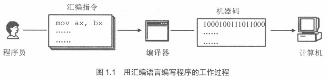
Our programs can only execute in the CPU in the form of machine code, so assembly language needs to be converted into machine code, which requires the use of a compiler:
2. Components of Assembly Language
| Category | Description | Corresponding Machine Code | Execution Entity |
|---|---|---|---|
| Assembly Instructions (Core) | Mnemonic for machine code | Yes | Computer (executes corresponding machine code) |
| Pseudoinstructions | No actual corresponding machine code logic, assists the compilation process | No | Compiler |
| Other Symbols (e.g., +, -, *, /, etc.) | Used to express operations and logic, participates in the compilation phase | No | Compiler |
3. Instructions and Data
All our programs run in the CPU, and to make the CPU work, we must provide it with data and instructions. Data and instructions are stored in the memory, which we commonly refer to as RAM.
In disks and memory, data and instructions are indistinguishable, both are binary information, but when the CPU is working, it interprets them as data or instructions based on need.
This is like the pieces on a Go board; they are essentially the same in the box, but have different interpretations during a game.
For example, the binary information in memory <span>1000100111011000</span> can have the following interpretations:
| Interpretation Type | Original Binary Information | Actual Interpretation |
|---|---|---|
| Data | 1000100111011000 | 89D8H |
| Instruction | 1000100111011000 | mov ax,bx |
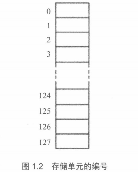
4. Memory Units
The memory is divided into several memory units, each unit is sequentially numbered starting from 0. For example, if a memory has 128 units, the numbering goes from 0 to 127. These <span>numbers</span> can be seen as the addresses of the memory units in the <span>memory</span>. Just like a street, each house has a <span>house number</span>. As shown in the figure:
5. CPU Read/Write Operations on Memory (Three Lines)
To read data from <span>memory</span>, the CPU must first specify the <span>address</span> of the <span>memory unit</span> (i.e., the aforementioned <span>unit number</span>). In other words, it must first determine which memory unit’s data it wants to read. This is like finding someone on a street; you must first determine which house they live in.
Thus, for the CPU to perform <span>data read/write operations with the outside world</span>, it needs the following three types of information:
| Required Information | Explanation |
|---|---|
| Address Information | Address of the memory unit (address information) |
| Data Information | Data to be read or written (data information) |
| Control Information | Device selection, read or write command (control information) |
6. Transmission of Address, Data, and Control Information – Bus
From the above, we know that the CPU needs to obtain three types of information to perform data read/write operations with the outside world. So how is this information transmitted to the memory chip?
Clearly, electronic computers use electrical signals, so they use wires for transmission. In computers, there are <span>wires specifically connecting the CPU and other chips</span>, known as “bus”.
Visualizing the Bus:
| Bus Perspective | Explanation |
|---|---|
| Physically | A collection of wires |
| Logically | Address Bus, Control Bus, Data Bus |
Functions of Each Bus:
| Bus | Function |
|---|---|
| Address Bus | The width of the address bus determines the CPU’s theoretical addressing capability |
| Data Bus | The width of the data bus determines the amount of data transferred at once between the CPU and other devices |
| Control Bus | The width of the control bus determines the CPU’s control capability over other devices in the system |
Practical Demonstration as Shown:
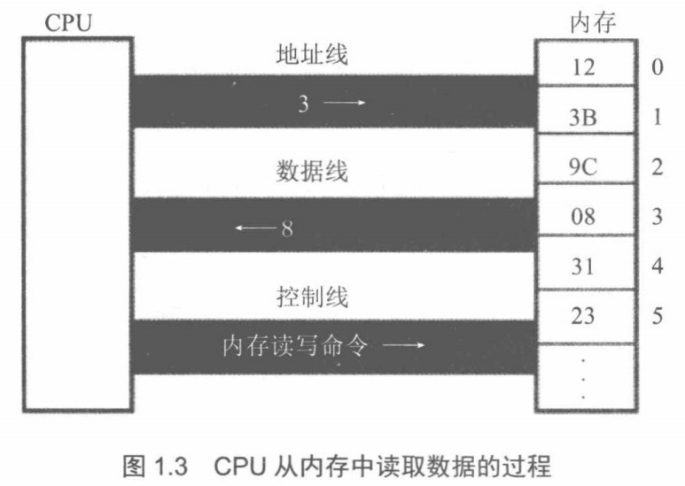
Corresponding Process:
(1) The CPU sends out <span>address information 3</span> through the <span>address line</span>.
(2) The CPU sends out a <span>memory read command</span> through the <span>control line</span>, selects the <span>memory chip</span>, and notifies it to read data from it.
(3) The memory sends the <span>data 8</span> from unit 3 through the <span>data line</span> to the CPU.
7. Address Bus
| Address Bus Related | |
|---|---|
| Purpose | The CPU selects the specified memory unit through the address bus. |
| Addressing Range | The number of memory units the CPU can select through the address bus is the size of the addressing range. |
For example, if the size of an address bus is N, then the addressing range is clearly <span>0~2^N-1</span>, because each line has <span>2 variations</span>.
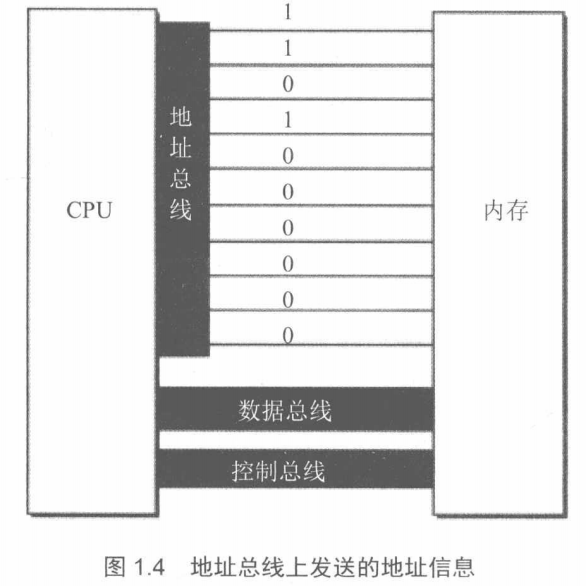
For instance, a CPU with <span>10 address lines</span> can address memory address 11 as shown in the following diagram:
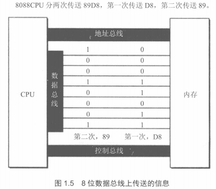
8. Data Bus
After the CPU selects the address through the address bus, it begins the data transfer. The data transfer between the CPU and memory or other devices is done through the data bus. The width of the data bus determines the data transfer rate between the CPU and the outside world. For example, 8 data lines can transfer 8 bits of binary information (i.e., 1 byte) at once.
Assuming the data to be transferred is <span>89D8H</span>, the following shows the data transfer situation under 8-bit and 16-bit data buses: