Abstract:To address the increasing scale and complexity of automotive software development, the AUTOSAR standard has been proposed as a standardized software development process. When developing automotive software based on AUTOSAR, it is required to adopt a component-based approach. Components related to ECU hardware, such as Complex Device Drivers (CDDs) and operating systems, must be developed for each target ECU hardware. This paper presents a method for automatically generating ECU hardware-related descriptions and corresponding CDD software components. In our approach, CDDs are generated by merging device driver form files and ECU hardware configuration files. The device driver form files address the differences between ECU hardware. Descriptions related to the target ECU hardware are abstracted using a Domain-Specific Language (DSL) and described in the ECU hardware configuration files. Furthermore, the ARXML description of the software component can be generated simply by describing the configuration using DSL. As a case study of this method, we developed an automatic braking system using a remote control car kit and a remote control car control system. The contribution of our method lies in its ability to automatically generate AUTOSAR-compliant CDD software components for each ECU hardware. When the ECU hardware is replaced with another type, CDD software components suitable for the new ECU hardware can be easily obtained. Additionally, the tool can generate correct ARXML descriptions. Therefore, it is expected to alleviate the burden on developers and improve productivity in automotive software development.
Original Authors: Hideki Hirose, Hideki Takase, Kazuyoshi Takagi, Naofumi Takagi
Original Title: A Generation Method of ECU-Hardware-Dependent Description of Complex Device Drivers in AUTOSAR
Compiled by: Yuan Dongdong, Yuan Xixi


01. Introduction
Today, with the growing functional requirements, the scale and complexity of automotive software are continuously increasing. Additionally, the number of Electronic Control Units (ECUs) installed in vehicles has also increased. For example, luxury cars contain more than 140 ECUs.
To address these issues, an alliance of several companies in the automotive field has provided AUTOSAR (Automotive Open System Architecture) as a specification for automotive software. AUTOSAR aims to standardize automotive software architecture and enable component-based development of automotive software. In AUTOSAR, automotive software is divided into multiple layers, with each component located in its respective layer. Since the application layer is hardware-independent, application components can be reused in other automotive systems. In contrast, Complex Device Drivers (CDDs) and some operating systems are located in hardware-dependent layers. Therefore, these components must be developed for each target hardware.
When developing CDDs, it is necessary to describe the design of the CDD components, and this must be done using ARXML (a specific XML format based on AUTOSAR patterns). The lack of readability in ARXML complicates the development process.
This paper proposes a method for automatically generating CDD software components (CDD SW-C). By simply writing information related to ECU hardware using a Domain-Specific Language (DSL), CDD software components can be generated. Additionally, the ARXML description of the software component can be generated by describing the configuration using DSL.
In the proposed method, CDDs are generated by merging device driver form files and ECU hardware configuration files. The device driver form files address the differences between various ECU hardware, implementing descriptions in the original device driver that are independent of ECU hardware. On the other hand, information related to ECU hardware (such as operating frequency and pin locations) is described in the ECU hardware configuration files.
Information about software components that developers wish to integrate into existing automotive systems is described in additional software component configuration files. By merging the additional software component configuration files with the ARXML files in the existing system, an integrated ARXML file is generated.
As a case study of this method, we developed an automatic braking system using a remote control car kit and a remote control car control system. We implemented this method as a CDD generator in Python and developed a device driver form file for the distance detection sensor in C. Next, we created ECU hardware configuration files for two types of ECU hardware. By inputting these files into the generator, we obtained CDD software components for the distance detection sensor for each hardware. Additionally, we developed an application software component that automatically brakes the vehicle based on the distance provided by the sensor. We described the configurations of the CDD software component and the application software component using DSL and combined these descriptions with existing ARXML files through the generator. We executed the integrated system on the remote control car kit and confirmed its normal operation.
The contribution of our research lies in the ability to generate CDD software components simply by writing DSL descriptions. When the ECU hardware is replaced with another type, CDD software components suitable for the new ECU hardware can be easily obtained. Furthermore, correct ARXML descriptions can be generated from the DSL descriptions of the software components. This means that integrating CDD software components into existing automotive systems can be accomplished solely using our tool. Therefore, it is expected to reduce the workload and cost of CDD development.
02. AUTOSAR
2.1 ECU Architecture in AUTOSAR
As shown in Figure 1, the ECU architecture in AUTOSAR consists of four layers: AUTOSAR software layer, AUTOSAR middleware layer, basic software layer, and ECU hardware.

Figure 1. ECU Architecture in AUTOSAR
AUTOSAR enables component-based development, so development is conducted for each component. Furthermore, when developing higher-level components, developers do not need to consider physical configurations. This makes it easy to improve components and reuse them in other automotive systems, thereby reducing development costs. However, some components in the basic software layer (such as CDDs) depend on ECU hardware, so they need to be developed for each target ECU hardware.
2.2 Software Development Process
The process of developing automotive software based on AUTOSAR is as follows:
1. Software Component Description:Determine the functions to be implemented by each software component and design the connections between software components.
2. System Description:Describe the definition of the system, including ECUs and software components.
3. ECU Configuration:Collect the information required to generate basic software and runtime environment (RTE) for each ECU.
4. ECU Integration:Implement ECU-dependent initialization processes, generate basic software and RTE, and build the entire software.
All information (such as system composition) must be described using ARXML. ARXML is a specific XML format based on AUTOSAR patterns. An example of ARXML description is shown in Figure 2. Ports, runnable entities, and interfaces are described using tags specified by AUTOSAR. Due to the lack of readability in ARXML, manually editing ARXML files is challenging.

Figure 2. Example of ARXML Description
03. Automatic Generation Method for Complex Device Drivers
3.1 Overview
As a solution to the challenges of CDD development, we propose a method for automatically generating CDD software components.
The overview of the CDD generator is shown in Figure 3. Device driver form files, ECU hardware configuration files, original ARXML files, and additional software component configuration files are input into the generator. The software component generator generates CDD software components by merging device driver form files and ECU hardware configuration files. The ARXML generator appends the ARXML description of the software component to the original ARXML file.
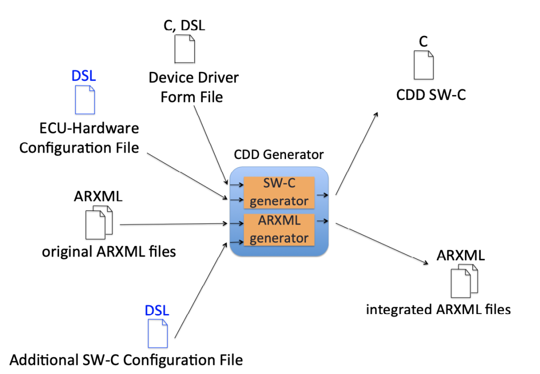
Figure 3. Overview of CDD Generator
3.2 Software Component Generator
Figure 4 shows an example of the description of device driver form files and ECU hardware configuration files.
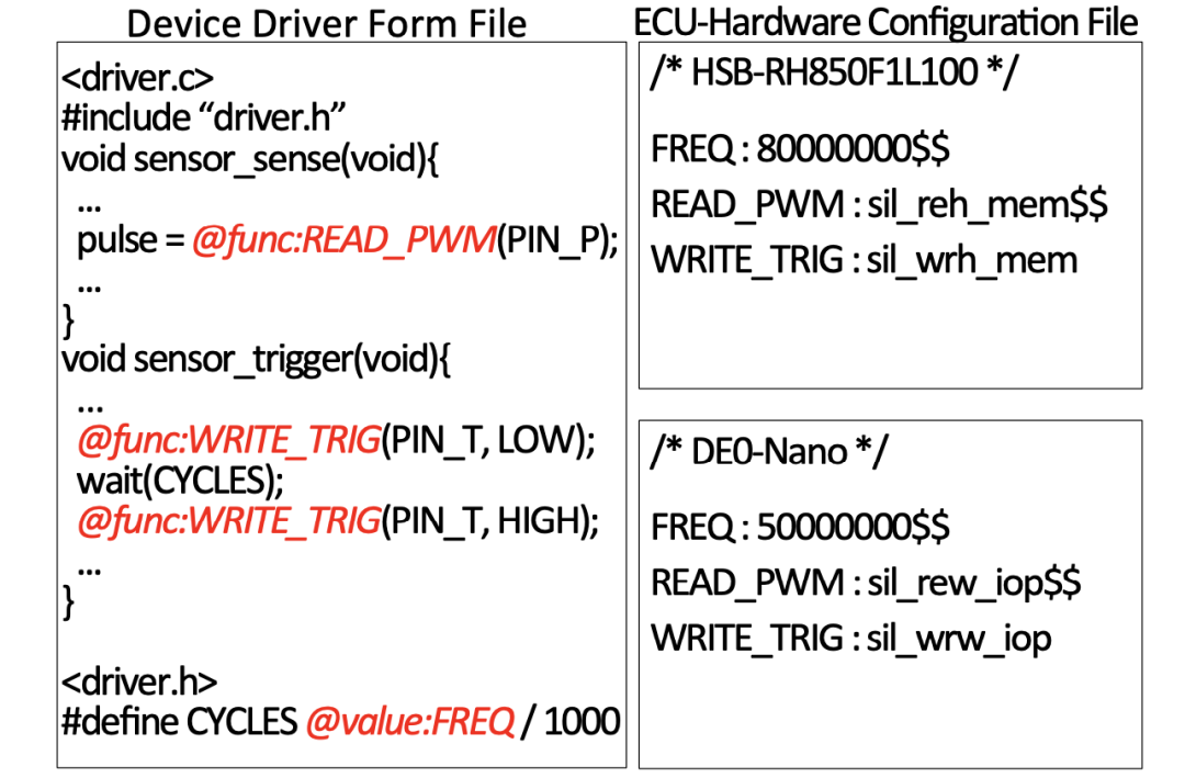
Figure 4. Example of SW-C Generator File Input Description
In the device driver form file, only descriptions that are independent of ECU hardware in the original device driver are implemented. Code related to ECU hardware is described using “abstract expressions,” such as ‘@<desc>:<name>’. In <desc>, the abstract code types are provided, such as functions (func), values, and code blocks (block). For example, ‘@func:READ_PWM’ indicates that a function is abstracted and named ‘READ_PWM’. The parts that are independent of ECU hardware are written in a language used in existing automotive systems (such as C).
In the ECU hardware configuration file, information related to ECU hardware (such as operating frequency and pin locations) is described using DSL. The code corresponding to the abstract expressions in the device driver form file is described using the delimiter ‘:’ and the terminator ‘$$’, as follows:

Abstract expressions can represent various types of code, such as parameters and functions. In the definition file, the code types that each abstract expression should describe in the ECU hardware configuration file are specified. As shown in Figure 5, the definition file is described using XML. In <exp>, a brief description, name, and type are provided for each abstract expression. If the abstract expression represents a function, the return type of the function and the parameters of the function are also specified. <args> contains a certain number of <arg>, each of which includes a brief description, number, and type, with the number indicating the order of the parameters. It is assumed that the definition file is provided for each device along with the device driver form file.
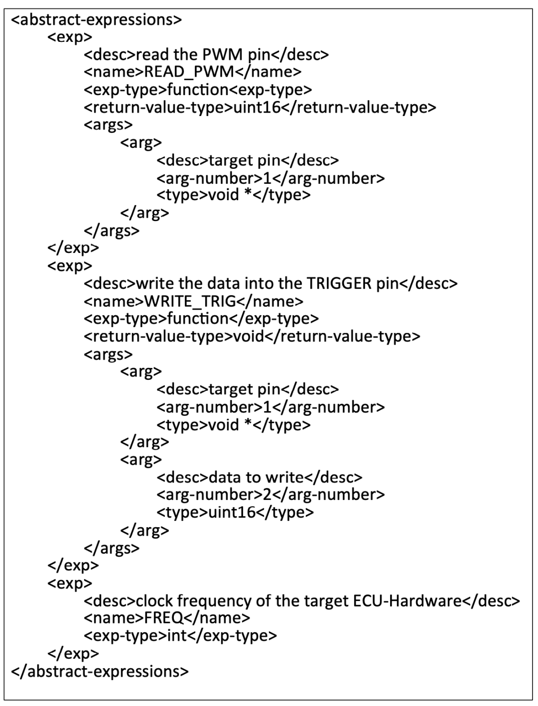
Figure 5. Example of Definition File Description
In the example code shown in Figure 4, three abstract expressions are defined. As described in the definition file in Figure 5, ‘READ_PWM’ is a function for reading the PWM pin connected to the sensor, returning a uint16 value, with a void type parameter as the target pin. ‘WRITE_TRIG’ is a function for writing data to the TRIGGER pin connected to the sensor, returning void, with two parameters, one for the pin (type void) and another for the data (type uint16). ‘FREQ’ represents the int value of the frequency used by the ECU hardware.
The generator references the definition file to check whether the code described in the ECU hardware configuration file is correct, confirming the code type, number of parameters, and parameter types.
When using this tool, developers must create ECU hardware configuration files for the target ECU hardware based on the definition file. By inputting the ECU hardware configuration file and the device driver form file into the software component generator, CDD software components for the target ECU hardware can be obtained. As a use case for the software component generator, we consider the development of replacing ECU hardware in existing automotive systems. In this case, developers do not need to recreate CDD software components for the new target ECU hardware but can obtain these CDD software components by writing some descriptions using DSL.
3.3 ARXML Generator
Figure 6 shows an example of the description of the additional software component configuration file, with the red part corresponding to the ARXML description in Figure 2. This file contains information about the software components that developers wish to integrate into existing automotive systems, the interfaces of these software components, and the connectors that link the existing software components with them. The information to be added to the system description file and configuration file is described in the description and configuration sections, respectively.
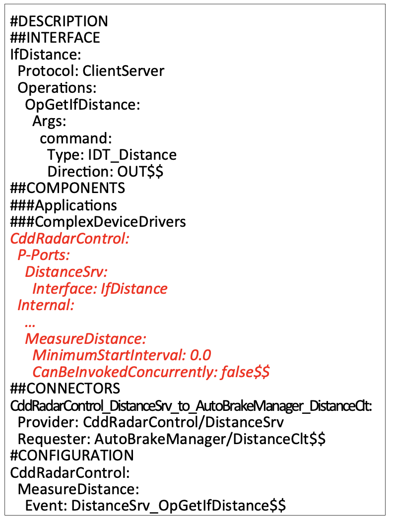
Figure 6. Example of Additional SW-C Configuration File Description
The description section starts with ‘#DESCRIPTION’, followed by blocks for communication interfaces, software components, and connectors, starting with ‘##INTERFACE’, ‘##SWCS’, and ‘##CONNECTORS’, respectively. The block for software components consists of two sub-blocks for application software components and CDD software components, starting with ‘###Applications’ and ‘###ComplexDeviceDrivers’, respectively. In each block, the first line writes the component name with a delimiter ‘:’, and in the following lines, the component information is described with a deeper indentation (two spaces), and the block ends with the terminator ‘$$’. The items to be described in the description section are listed in Table 1, with the items and their corresponding descriptions separated by the delimiter ‘:’. When enumerating parameters for operations and data, the first line declares the item name, and the next line describes the name of the operation or data with a deeper indentation, followed by enumerating the parameters with a deeper indentation.
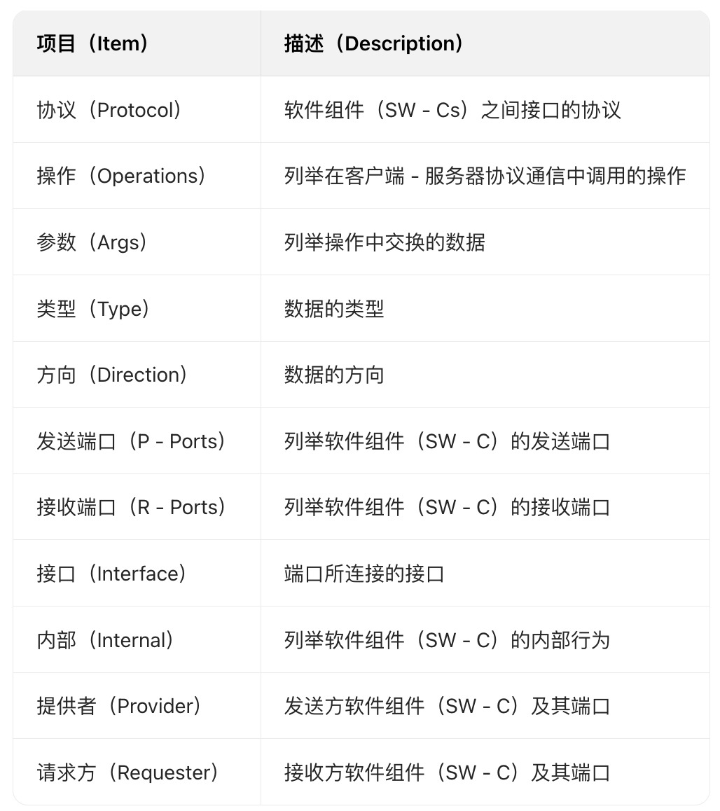
Table 1. Items to be Described in the Description Section
The configuration section starts with ‘#CONFIGURATION’, and in the following lines, the startup information for the runnable entities of the software components is described in blocks, with the same symbols and indentation rules as the description section. The items to be described in this section are listed in Table 2.
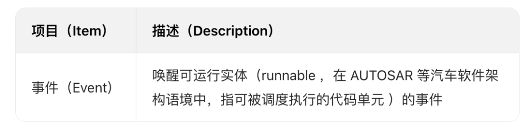
Table 2. Items to be Described in the Configuration Section
The system description file and configuration file of the existing system are input into the tool, and the generator references the additional software component configuration file to integrate the information into these ARXML files.
Using the ARXML generator, developers can complete the integration of CDD into existing systems without using expensive commercial tools, thus reducing the cost of CDD development.
04. Case Study
We implemented the proposed method as a CDD generator in Python. Using this generator, we developed CDDs for distance detection sensors for two types of ECU hardware (HSB-RH850F1L100 and DE0-Nano). Additionally, we developed an automatic braking application that operates based on the distance provided by the sensor. We integrated this application and CDD software components into the existing system and confirmed that the integrated system worked normally on the remote control car kit.
4.1 Objectives
4.1.1 Remote Control Car Kit
There are remote control car kits available on the market that can use microcomputer boards and FPGA boards as ECU hardware to control remote control cars. HOKUTO DENSHI’s HSB-RH850F1L100 and Altera’s DE0-Nano can be used as ECU hardware. This kit can simulate automotive software development on a small scale. The appearance of the kit is shown in Figure 7.
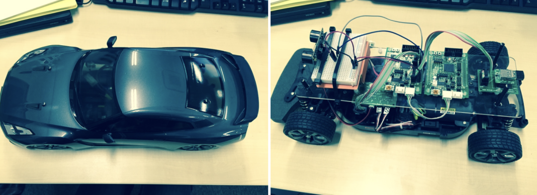
Figure 7. Appearance of the RC Car Kit
4.1.2 Remote Control Car Control System
The Embedded Computing Systems Center of Nagoya University and its collaborators developed the remote control car control system according to the AUTOSAR specification. The operating system of this system uses TOPPERS/ATK2 provided by the TOPPERS project, with the target hardware being HSB-RH850F1L100 and DE0-Nano. Additionally, the program for HSB-RH850F1L100 has two versions: the operating system task version and the software component version. In the operating system task version, all applications are implemented as operating system tasks; while in the software component version, they are implemented as software components. Only the operating system task version of the program is provided for DE0-Nano.
According to the AUTOSAR specification, running software components requires RTE, which can be generated using the RTE generator provided by the TOPPERS project.
4.1.3 Distance Detection Sensor
We adopted the URM37 as the distance detection sensor, which measures the distance to obstacles ahead by emitting ultrasonic waves. The behavior of the URM37 is shown in Figure 8. When a trigger pulse is sent to the COMP/TRIG pin of the URM37, it measures the distance and returns a pulse through the PWM pin, with the width of the returned pulse proportional to the measured distance, where 50μs corresponds to 1cm.

Figure 8. Behavior of URM37
4.2 Application of Our Method to CDD Generation
The CDD for URM37 roughly requires two functions: pulse sending/receiving function and pulse width measurement function. Therefore, we implemented the device driver form file for URM37, which includes an initialization module and modules for these two functions. According to the rules specified in 3.2, the pin locations, operating frequency, and other ECU hardware-dependent processes are abstracted in the device driver form file. The device driver form file consists of 112 lines, with 14 abstract expressions abstracting 15 locations.
Next, we implemented ECU hardware configuration files for HSB-RH850F1L100 and DE0-Nano, describing the specific code for the abstract expressions in the device driver form file according to the rules in 3.2. The HSB-RH850F1L100 file consists of 46 lines, while the DE0-Nano file consists of 14 lines.
By inputting these files into the tool’s software component generator, we obtained CDD software components for each ECU hardware. The generated CDD software components consist of 144 lines for HSB-RH850F1L100 and 112 lines for DE0-Nano.
4.3 Implementation of Automatic Braking System
We developed an automatic braking application software component that automatically stops the vehicle when the distance to an obstacle ahead is less than a threshold. The system configuration with the automatic braking application is shown in Figure 9. The automatic braking application software component calls the distance detection sensor CDD software component to obtain the distance to the obstacle ahead, determines whether automatic braking should be executed, and sends instructions to the remote control car control system.
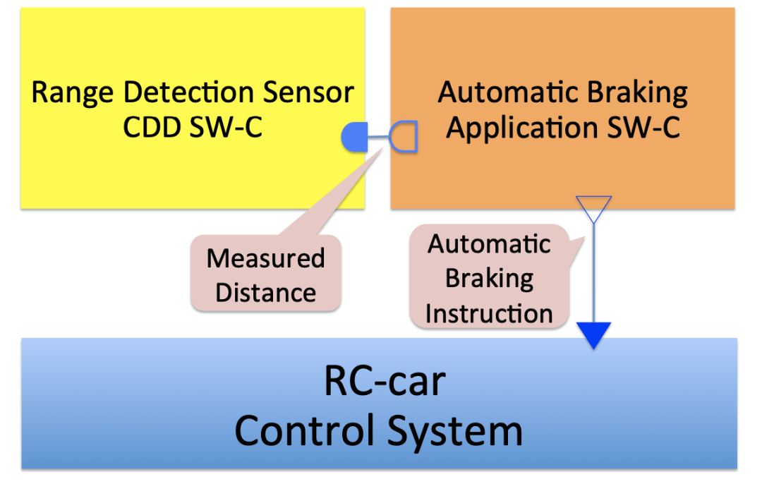
Figure 9. Configuration of the Developed System
When integrating this application with the software component version of the remote control car control system for HSB-RH850F1L100, we utilized the ARXML generator. We described the information of the distance detection sensor CDD software component and the automatic braking application software component in the additional software component configuration file. By inputting the original ARXML file of the remote control car control system and the additional software component configuration file into the ARXML generator, we obtained the integrated ARXML file. Since the software component version of the remote control car control system is not provided for DE0-Nano, we developed the necessary ARXML files without tools.
We built the software and downloaded it to HSB-RH850F1L100 and DE0-Nano, confirming that the automatic braking instructions were transmitted normally on the remote control car kit.
05. Related Work
There are several related methods that assist in the development of automotive software.
Some researchers have proposed using DSL for modeling situational awareness in vehicle-to-X applications. In their approach, application code is generated from DSL descriptions that define how the application operates, which helps to port applications to other automotive systems using different languages.
Other research has proposed a protocol analyzer with application layer communication abstraction and complex scenarios. The proposed protocol analyzer can specify, monitor, and test complex scenarios, and researchers have also proposed a DSL based on their method so that automotive software developers can use their method without special knowledge.
Some research has proposed a basic software (BSW) configuration generator. Their generator references spreadsheets of hardware-software interface (HSI) information and generates BSW drivers and software interfaces. Their method bridges the gap between model-driven systems engineering tools and software engineering tools, enhancing the model-based software engineering framework for automotive software.
Other research has proposed a method for relocating AUTOSAR components between ECUs without changing overall functionality, which helps developers compare possible architectures during the design or prototyping phase.
06. Conclusion
We proposed a method for generating CDD software components aimed at reducing the workload and cost of CDD development and improving the efficiency of automotive software development. When developing CDD software components using the proposed method, developers describe the necessary information related to the target ECU hardware in the ECU hardware configuration files using DSL. By inputting the device driver form files and ECU hardware configuration files into the proposed CDD generator, CDD software components can be obtained. Furthermore, by describing the configuration of the software components in the additional software component configuration file and inputting it along with the ARXML files of the existing system into the tool, developers can obtain the merged ARXML files.
The proposed method saves time and effort in developing CDDs, allowing CDD software components to be easily generated by simply writing DSL descriptions. When the ECU hardware is replaced with another type, CDD software components suitable for the new ECU hardware can be easily obtained. Additionally, when integrating the developed software components into existing automotive systems, appropriate integrated ARXML files can be obtained without the need for other ARXML editing tools.
In future work, we will evaluate our CDD generator by comparing the differences in code size and execution time between software components developed using this tool and those developed without it. We will also simplify the description rules in the additional software component configuration file. In the current rules, information about a software component is divided into configuration and description sections; for convenience, we hope to consolidate them into one place.
Disclaimer: The views expressed in this article are for sharing and communication purposes only. The copyright and interpretation rights of the article belong to the original authors and publishing units. If there are any copyright issues, please contact [email protected], and we will address them promptly.
Related Articles ●●
|Functional Safety Considerations for Basic Steering Systems
|Documentation as Code in Automotive Systems/Software Engineering
|New Line Control Brake System Launched by Nexteer for Automotive Manufacturers
|AUTOSAR Method Analysis and Technical Implementation
|Safety Architecture for Perception Performance Evaluation in Assisted and Autonomous Driving
|Basic Design of ECU Hardware for Functional Safety in Vehicle Network Communication
|ISO 21434 Cybersecurity Engineering Method
|Using Fault Injection to Validate AUTOSAR Applications According to ISO 26262
|Achieving Functional Safety ASIL Compliance for Autonomous Driving Software Systems
|Software Architecture Design for Autonomous Driving Systems (Part 2)
|Overall Chiplet Solutions for Autonomous Vehicles (Part 2): Communication Solutions