Reading this article will take approximately 5 minutes.
This article continues to explore the use of LED matrix displays to achieve a heart-beating effect.
1. Experiment Materials
-
Uno R3 Development Board
-
USB Data Cable
-
Breadboard and Jumper Wires
-
8×8 LED Matrix Display
2. Experiment Steps
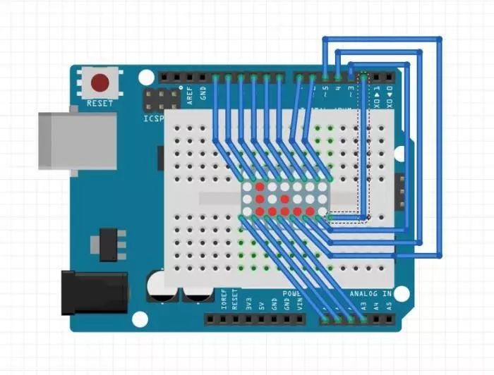
1. Build the circuit according to the schematic.
According to the pin definitions of the matrix display, connect the display’s [9, 14, 8, 12, 1, 7, 2, 5] to the development board’s [6, 11, 5, 9, 14, 4, 15, 2]; these 8 pins are the positive terminals of the LEDs;
Connect the matrix display’s [13, 3, 4, 10, 6, 11, 15, 16] to the development board’s [10, 16, 17, 7, 3, 8, 12, 13]; these 8 pins are the negative terminals of the LEDs.
Note that the Uno R3 development board’s A0~A5 can also be used as regular GPIO, numbered 14~19.
The experimental schematic is shown below:

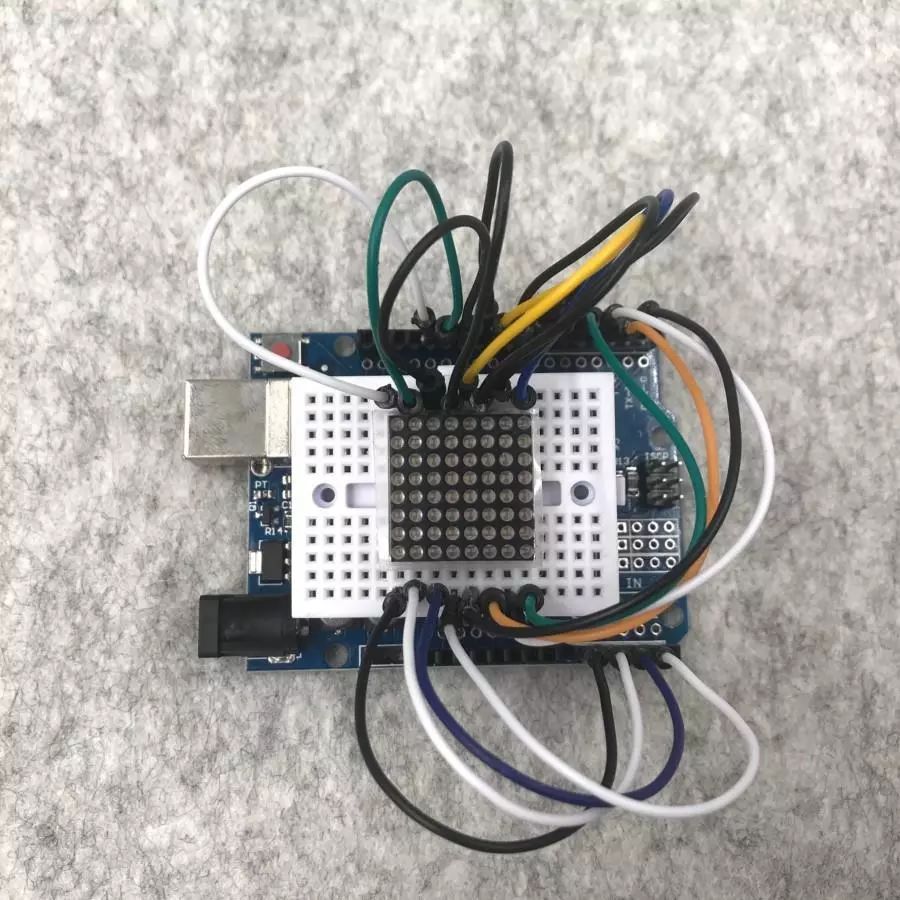
The physical connection diagram is shown below:

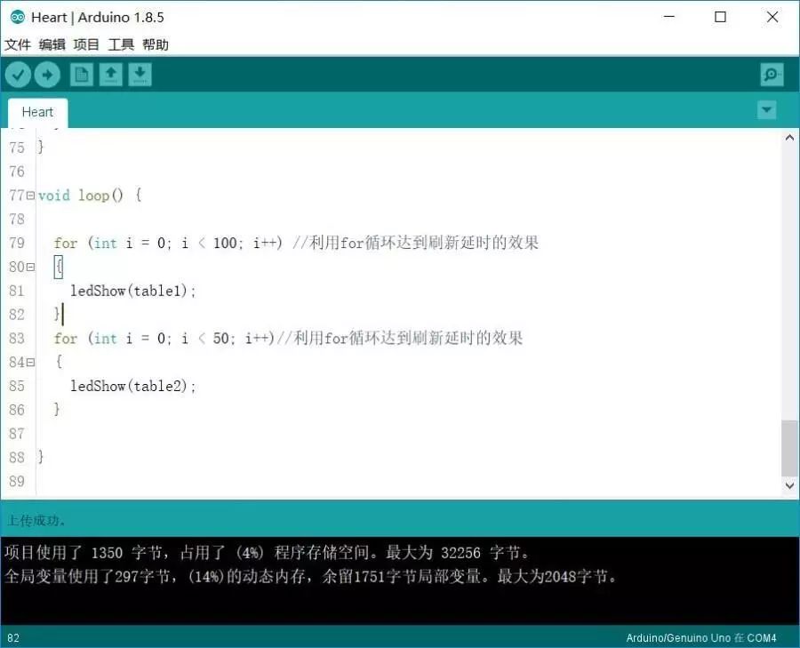
2. Create a new sketch, copy the code below to replace the auto-generated code, and save it.
  1/*
 2   Heart
 3   Heart-shaped display on matrix
 4*/
 5int leds[8] = {6, 11, 5, 9, 14, 4, 15, 2}; // Positive terminal pins of the matrix display
 6int gnds[8] = {10, 16, 17, 7, 3, 8, 12, 13}; // Negative terminal pins of the matrix display
 7
 8// Data for the large "heart"
 9int table1[8][8] =
10{
11  0, 0, 0, 0, 0, 0, 0, 0,
12  0, 1, 1, 0, 0, 1, 1, 0,
13  1, 1, 1, 1, 1, 1, 1, 1,
14  1, 1, 1, 1, 1, 1, 1, 1,
15  1, 1, 1, 1, 1, 1, 1, 1,
16  0, 1, 1, 1, 1, 1, 1, 0,
17  0, 0, 1, 1, 1, 1, 0, 0,
18  0, 0, 0, 1, 1, 0, 0, 0,
19};
20
21// Data for the small "heart"
22int table2[8][8] =
23{
24  0, 0, 0, 0, 0, 0, 0, 0,
25  0, 0, 0, 0, 0, 0, 0, 0,
26  0, 0, 1, 0, 0, 1, 0, 0,
27  0, 1, 1, 1, 1, 1, 1, 0,
28  0, 1, 1, 1, 1, 1, 1, 0,
29  0, 0, 1, 1, 1, 1, 0, 0,
30  0, 0, 0, 1, 1, 0, 0, 0,
31  0, 0, 0, 0, 0, 0, 0, 0,
32};
33
34void setup() {
35  for (int i = 0; i < 8; i++)
36  {
37    pinMode(leds[i], OUTPUT);
38    pinMode(gnds[i], OUTPUT);
39    digitalWrite(gnds[i], HIGH); // Pulling the negative terminal high to turn off all LEDs
40  }
41}
42
43void ledclean()
44{
45  for (int i = 0; i < 8; i++)// Turn off the display by pulling the positive terminals low and negative terminals high
46  {
47    digitalWrite(leds[i], LOW);
48    digitalWrite(gnds[i], HIGH);
49  }
50}
51
52// Heart display function
53void ledShow(int temp[8][8])
54{
55  for (int j = 0 ; j < 8; j++)
56  {
57    digitalWrite(gnds[j], LOW);
58    for (int i = 0; i < 8; i++)
59    {
60      digitalWrite(leds[i], temp[i][j]);
61      delayMicroseconds(100);
62    }
63    digitalWrite(gnds[j], HIGH);
64    ledclean();
65  }
66}
67
68void loop() {
69
70  for (int i = 0; i < 100; i++) // Use for loop to achieve refresh delay effect
71  {
72    ledShow(table1);
73  }
74  for (int i = 0; i < 50; i++)// Use for loop to achieve refresh delay effect
75  {
76    ledShow(table2);
77  }
78
79}
3. Connect the development board, set the corresponding port number and board type, and upload the program.

3. Experiment Phenomenon
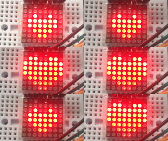
The heart shape on the matrix display is continuously beating.

4. Experiment Analysis
The program defines two two-dimensional arrays to store the display data for two different sizes of hearts. The display function uses two for loops to traverse the arrays. The loop() function does not use the delay() function for timing because, similar to digital tubes, this type of LED display device needs to be refreshed continuously. Using delay() would cause the display to flicker or even turn off. A for loop controls the number of displays to achieve the timing effect.
