In automotive MBD (Model-Based Design) development, the Delay Module in Simulink is an extremely fundamental yet crucial component. For example, by using the Delay Module, we can simulate physical world delays, including delays in sensors, actuators, and communications:
-
Actual sensors (such as temperature, pressure, and position sensors) experience physical delays (mechanical response, filtering, signal processing time) from perceiving physical quantities to outputting electrical signals. The Delay Module can be used to simulate this inherent delay in the model.
-
Actuators (such as throttle motors, solenoids, and relays) also require time from receiving control signals to producing actual actions, and the Delay Module can simulate this delay.
-
Communication delays: In distributed systems (such as communication via CAN/LIN/FlexRay/Ethernet), signals transmitted between ECUs incur delays, which can be simulated using the Delay Module.
We can also control timing requirements in algorithms, including preventing algebraic loops, discrete control logic, and state memory.
-
When a model requires the current output value to compute the current input value, it creates an algebraic loop, leading to simulation failure. Inserting a Delay Module in the feedback path (even if the delay time is one simulation step) is a standard method to break the algebraic loop.
-
In sample period-based discrete controllers, the Delay Module is often used to store the value from the previous sampling moment for implementing differential calculations and digital filters. For example, to implement a first-order low-pass filter
<span><span>y(k) = a * y(k-1) + b * u(k)</span></span>, where<span><span>y(k-1)</span></span>needs to be provided by the Delay Module. -
Storing the previous state value of the system for subsequent calculations (such as state retention during mode switching and historical data analysis in fault diagnosis).
This article mainly shares the most common uses of the Delay Module in ECU application layer software model development: one is to use the Delay Module to obtain the previous value, and the other is to use the Delay Module for initialization.
1 Delay Module Parameter Description
When using the Delay Module, the most common considerations are to correctly set three parameters:
-
Delay Length, which specifies how many sample points to delay.
-
Initial condition, which means that at the start (t=0), the Delay Module needs to output an initial value (i.e., the output before the delay is filled). This value is determined by the Initial Condition parameter.
-
Sample Time, which must be explicitly set (it is strongly recommended to set it to a value other than
<span><span>-1</span></span>). It defines the sampling time of the module and determines the granularity of the delay. It must be coordinated with the base sampling time of the model or the sampling time of the signal source.
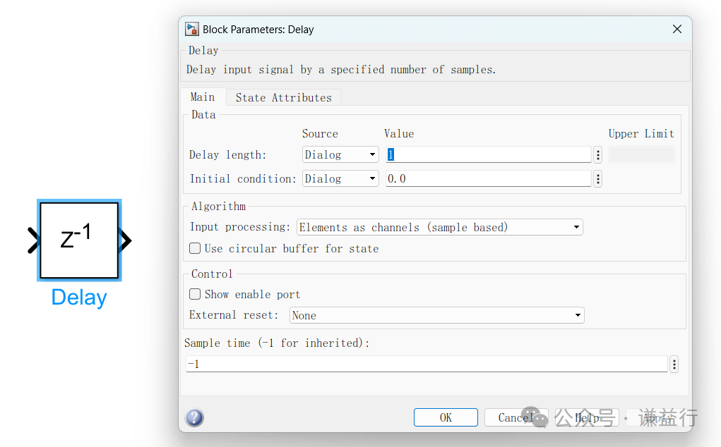
It is particularly important to handle the initial condition (Initial Condition). Typically, zero initialization (<span><span>0</span></span>) is the most common and simplest, suitable for most scenarios where the signal is unknown or the initial state should be zero; however, specific value initialization is also common, setting the initial state or initial value according to software logic requirements.
2 Using the Delay Module to Obtain Previous Value
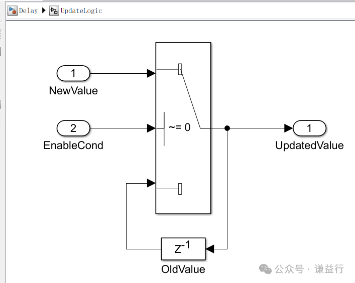
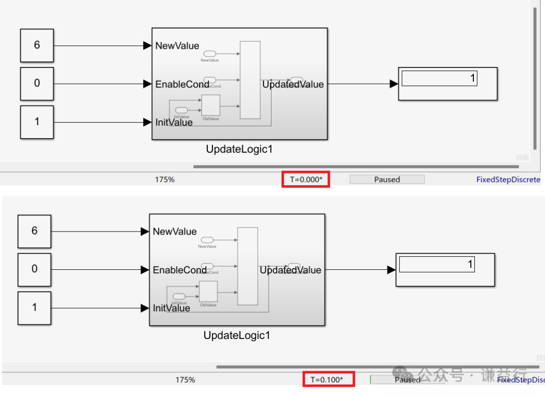
The use of the Delay Module in MBD is ubiquitous, and the most common application is to obtain the previous value (cycle) of a signal. The following diagram shows the most common usage, where when a signal does not need to be updated, it retains the previous value, as shown below:
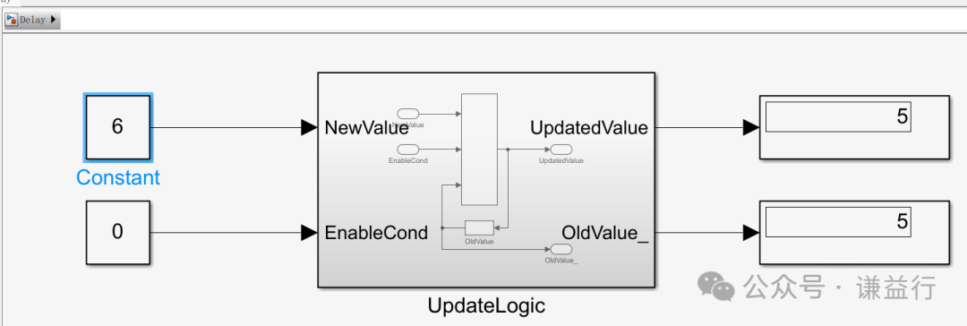
We can simulate this model to see the effect. As shown in the following diagram, when the enable condition is not met, i.e., EnableCond=0, even if the new value is 6, the previous value (5) is still output.
Additionally, when using the Delay Module to obtain the previous value, MBD often encounters situations where specific initial values need to be set. For example, for an ECU usage lifetime counter, it is usually written on power down and read on power up, meaning it needs to read the last value to continue counting the ECU usage lifetime. In this case, we need to configure the Initial Condition parameter of the Delay Module to Port mode, allowing us to use the previous ECU usage lifetime value and continue counting, as shown below:
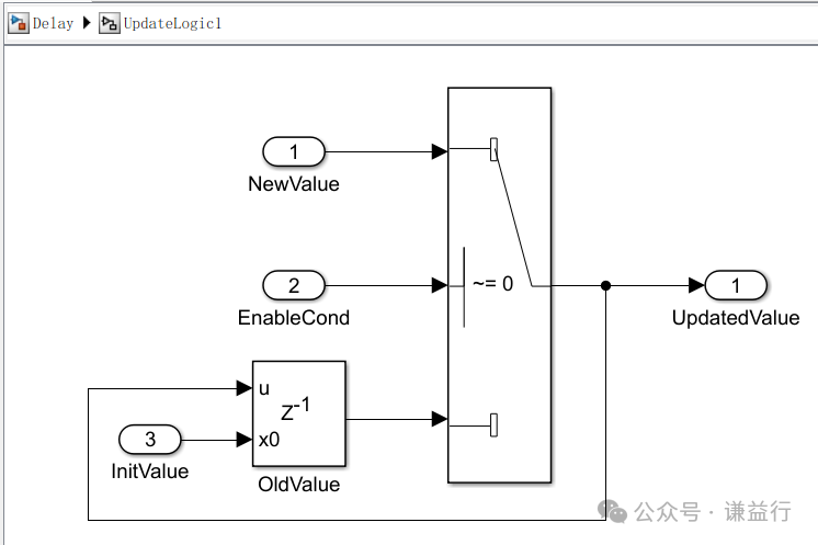
We can understand this through a specific application example. For instance, if the initial value is 1 and the new value is 6, as long as the enable condition is not met, it will continuously output the initial value until the enable condition is met, at which point it will output the new value.
This is a simple explanation of using the Delay Module to obtain the previous value. Next, let’s understand how to use the Delay Module for initialization.
3 Initialization Using the Delay Module
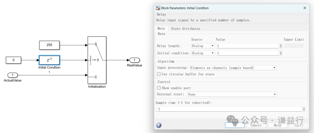
The logic for initializing with the Delay Module is quite simple; a logic runs only once at the very beginning and then never runs again. Let’s understand this through an example. Suppose we have a signal, and we want to initially set its value to 255, and then based on specific conditions, obtain its actual value. Therefore, we use the Delay Module, setting its delay to one cycle, initial condition to 1, and input to 0, to achieve our expected effect.
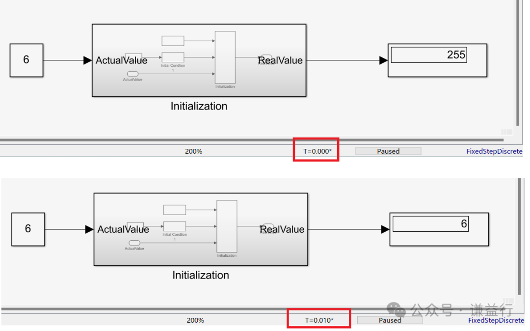
Simulating the above logic verifies its effect. We can see that initially, it outputs 255, and then in the next moment, it outputs based on the actual value = 6, completely in line with expectations.
This concludes the simple introduction on how to use the Delay Module for initialization. For more questions regarding the use of the Delay Module, feel free to leave comments for discussion.
Creating content is not easy, please like, follow, and save.!( Qian Yixing changed name Automotive Electronics Engineering Circle) Automotive R&D group chat, interested friends please add the group owner: prOmiseyes, with a note: company + position to join the group. Limited to automotive industry personnel.
Articles on ECU application layer software models are continuously updated, teaching you application layer development from scratch:
- Example 1 of building ECU application layer software model (qq.com)
- How to automatically generate code for ECU application layer software model 2 (qq.com)
- How to run ECU application layer software periodically 3 (qq.com)
- Code generation configuration related to ECU application layer software model and hardware 4 (qq.com)
- Data Dictionary DD in ECU application layer software model 5 (qq.com)
- Data Dictionary Storage Class in ECU application layer software model 6 (qq.com)
- Fixed-point implementation in ECU application layer software model 7 (qq.com)
- Five fixed-point implementation methods in ECU application software model 8 (qq.com)
- Custom storage class in ECU application layer software model 9 (qq.com)
- Summary of model-generated code in ECU application layer software model 10 (qq.com)
- CAN reception in ECU application layer software model 11 (qq.com)
- Data stream of CAN message reception in ECU application layer software model 12
- How to leverage AI in ECU software development? Application of Kimi in MBD development environment 13
-
Detailed explanation of unit test coverage CC, DC, and MCDC in ECU application layer software model 14
-
Application and Principles of Calibration Quantity and Observed Quantity in ECU Application Layer Model Development 15
-
Using for loops in ECU application layer model development 16
- Using if-else in ECU application layer model development 17
- Using initialization functions in ECU application layer model development 18
-
Counter in ECU application layer model development 19
-
Basics of Assignment Module in ECU application layer model development 20