Author Introduction
Engaged in the control development of three-phase asynchronous motors and permanent magnet synchronous motors for over ten years, proficient in sensorless FOC control. Products involved include inverters, servos, power tools, vacuum cleaners, propellers, drones, air compressors, etc. Power range includes 100W to 100kW, voltage range includes 14VDC to 660VAC.
Since 2020, I have been sharing technical knowledge on Zhihu and WeChat public accounts, with a consistent philosophy of respecting knowledge, labor, and copyright, continuously providing value. I hope all my peers receive adequate compensation and that more people are willing to engage in the motor control industry. Currently, I have a personal brand on platforms like Xianyu, CSDN, Bilibili, and Douyin.

Introduction
In the previous article, we analyzed the first half of Renesas FOC, including the speed loop, weak magnetic control, and current loop.
Some friends have given feedback that the depth of the article was insufficient. I do not deny this, and I feel quite helpless. At my age, I have to balance family responsibilities and career development, and I have stopped many scattered tasks. Writing articles can only be a hobby; this article was conceived while I was traveling on the high-speed train.
I also envy young friends who can continually delve into new technologies. At this stage, I am more focused on career direction, business connections, and product lifecycle, and I simply do not have the energy to explore certain new technologies. More of my focus is on project implementation, product stability, and customer satisfaction. I hope for your understanding.
This article analyzes the second half, including position estimation, open-loop startup, and FOC structure.
Method Overview
Position Estimation
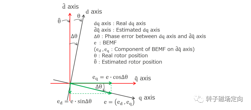
Renesas’s sensorless position estimation is based on the BEMF back EMF method. In the d-q rotating coordinate system, we construct the real dq coordinate system and the estimated dq coordinate system, as shown in the figure below:
The voltage equations in the dq coordinate system are as follows:

By equating the back EMF as disturbances, the voltage equation simplifies to:

The d-axis voltage equation can be rewritten as:

The d-axis current and voltage disturbances are treated as state variables, written in the form of the following state equation:


The estimated current and estimated voltage disturbances can be expressed in the following form:
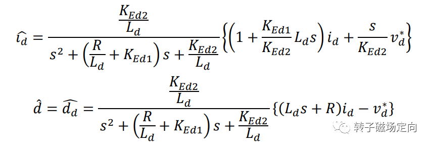
From the equations, we can see that ^Id and ^dd are both second-order systems with inputs of Id and V*d, where ^dd represents the d-axis disturbance, and ^dq represents the q-axis disturbance.
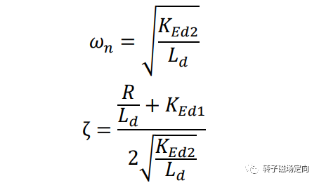
The natural frequency and damping ratio can be tuned as follows:
The estimation gain is designed as follows:
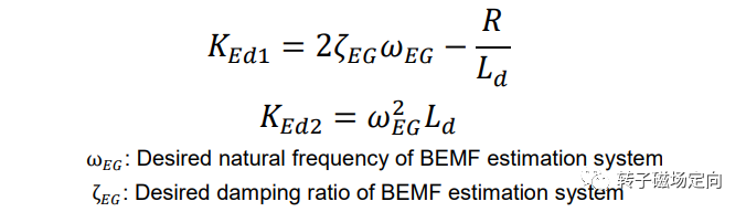
Where Ked1 represents the bandwidth of the d-axis estimator.
The state equation for estimation is modified to the following form:
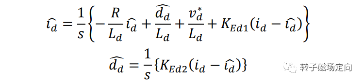
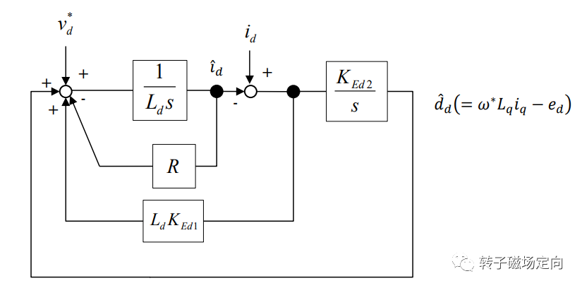
Based on the state equation, we can draw the entire d-axis back EMF estimation system block diagram:
After estimating the current and voltage disturbances in the dq axis, we obtain the dq axis back EMF:
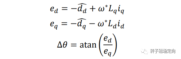
According to the definitions of the real coordinate system and the estimated coordinate system, we can calculate the angle error between the estimated angle and the actual angle by performing arctangent on the dq estimated back EMF.
The angle error is fed into the phase-locked loop (PLL) to output the estimated angle and estimated speed:
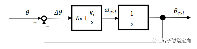
The closed-loop transfer function of the PLL is as follows:

Both the speed loop and the current loop belong to second-order lag systems with zero points, the bandwidth and damping ratio are calculated as follows:
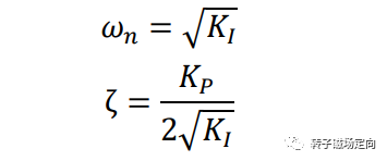
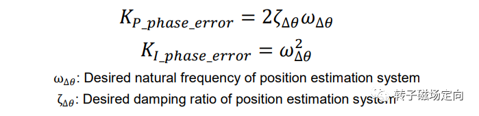
Renesas’s position estimation is different from sliding mode or Luenberger and does not belong to extended back EMF; there should be related articles.
FOC Structure
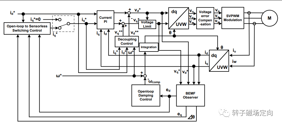
In the initial stage, open-loop control is used, i.e., I-f damping control, similar to power angle compensation, with Id fixed amplitude and Iq=0. The current loop adds feedforward, and Uq is limited by the calculation result of Ud to prevent current loop saturation. The reference speed plus power angle compensation is integrated to obtain the angle for current decoupling and coordinate inverse transformation. The overall block diagram is shown below:
After using I-f open-loop startup, switch to closed-loop FOC control mode, as shown in the figure below:
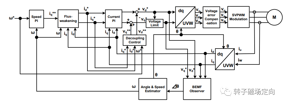
The angle estimation outputs the estimated angle error, which is fed into the phase-locked loop to output estimated speed and estimated angle. Weak magnetic control requires the joint participation of Id, Iq, and current speed in calculations. The current loop adds feedforward, and Uq is limited by the calculation result of Ud to prevent current loop saturation. After inverse transformation, compensation must also be added to the three-phase voltage, which will be discussed later.
Open-Loop Startup
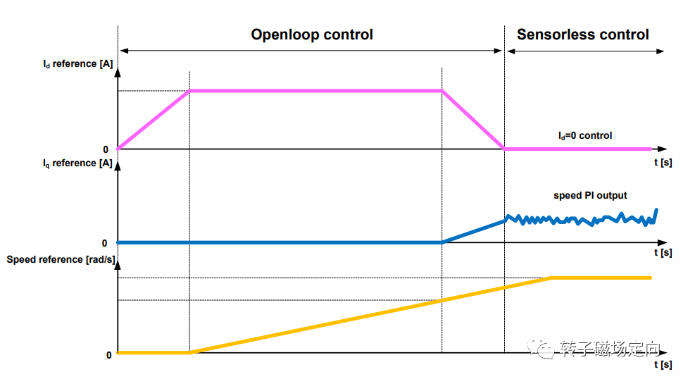
In the low-speed region, Renesas uses open-loop I-f control instead of FOC, mainly due to the influence of nonlinear factors at low speeds, which causes FOC estimation to have non-negligible errors.
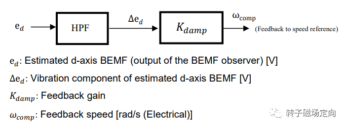
To solve the oscillation caused by unstable I-f torque, the following damping control is adopted, extracting the high-frequency component of Eq to obtain the oscillation frequency, and applying damping compensation to the electrical angle based on the oscillation frequency to suppress speed oscillations.
When reaching the mid-speed region, the estimation error of FOC based on the back EMF model can be considered negligible, and the system gradually switches from I-f damping control to FOC control.
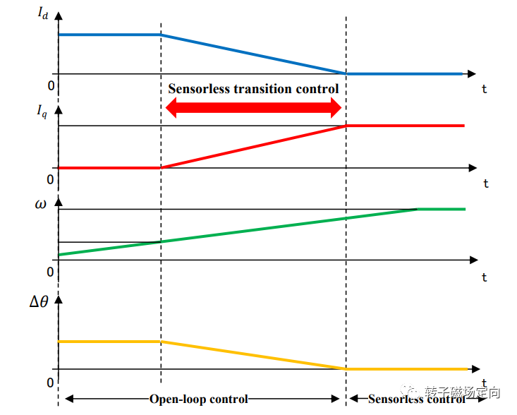
During the switch, especially under heavy load, the electrical angle of I-f and the actual rotor angle have a large error, and switching easily causes current surges.
To reduce the surge, the angle error is used as the loop input to calculate the need to gradually reduce the angle error of I-f to 0, with the loop output assigned to Iq, while Id gradually decreases. When the angle error converges to 0, the switching condition is met, and the system switches directly to FOC. Id gradually decreases, and Iq gradually increases, effectively reducing current surges through a gradual transition.
Voltage Error Compensation
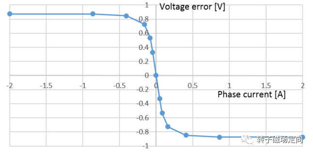
The voltage error here mainly refers to the discrepancy between the actual output voltage and the reference output voltage caused by dead time and MOSFET/IGBT switching delays.
The magnitude of the voltage error is related to the current direction, the switching time of the devices, and the dead time. As shown in the figure below, according to Renesas’s approach, it seems to calibrate the error based on the current and then add it to the voltage reference, rather than compensating separately for the dead time.
Startup Logic
The overall logic for open-loop I-f startup to switching to FOC is shown in the figure below:
Getting to Know the Author:
How Can Motor Control Engineers Earn High Salaries?
My House Buying Story
What is it like to have a monthly salary of 40,000 RMB?
Is it difficult to earn 100,000 RMB a month?
Professional Articles:
Is there still a market for Texas Instruments C2000?
2022 Development Trends in the Electric Control Industry
A Guide to Avoid Pitfalls in Learning FOC
Sensorless FOC Control for Aircraft Models Based on M0 MCU
How Powerful is MATLAB?
Nonlinear Observer Based on Magnetic Link Model