Author Introduction
Engaged in the control development of three-phase asynchronous motors and permanent magnet synchronous motors for over ten years, proficient in sensorless FOC control. The products involved include inverters, servos, power tools, vacuum cleaners, propellers, drones, air compressors, etc. The power range covers 100W to 100kW, and the voltage range includes 14VDC to 660VAC.
Since 2020, I have been sharing technology on Zhihu and WeChat public accounts, adhering to the consistent principle of respecting knowledge, labor, and copyright while continuously delivering value. I look forward to all colleagues receiving adequate compensation, and more people willing to engage in the motor control industry. Currently, I have personal IPs on Xianyu, CSDN, Bilibili, and Douyin.

Introduction
Renesas has been relatively low-key as a manufacturer, and its recognition in China is not as high as that of ST/TI/Infineon. However, those familiar with industry applications know that Renesas is a versatile giant in the MCU field for consumer, industrial, and automotive applications.
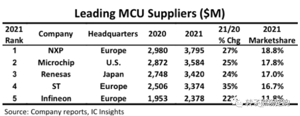
In the global top ten MCU manufacturers in 2021, Renesas ranked third and has consistently remained in the top three in recent years.
Today, this article will analyze the sensorless FOC in Renesas motor control solutions.
Method Overview
Current Loop
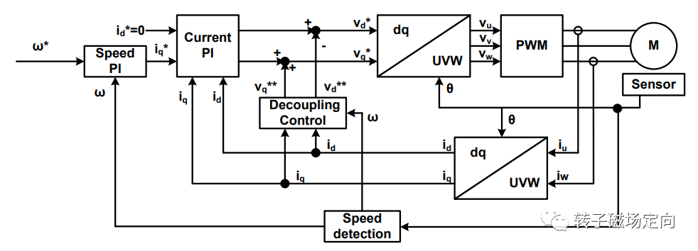
The above figure shows the overall system block diagram of FOC. The decoupling control adds the following feedforward to the PI output of the current loop, serving as the reference value for voltage to achieve good dynamic response at high speeds.
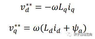
Adding feedforward is helpful to some extent, provided that the angle is accurate and the parameters do not vary too much. Generally speaking, customers do not measure the magnetic flux of the motor, so it becomes difficult to implement feedforward based on unknown magnetic flux.
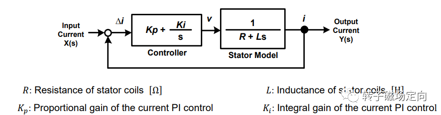
The current loop control block diagram is shown above. Ignoring external disturbances such as back EMF, the motor is equivalent to a static RL series load. The current loop includes a series PI correction link, and the closed-loop transfer function is derived as follows:
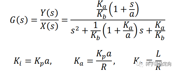
A second-order lag system with zero points, expressed in a colloquial form as follows:
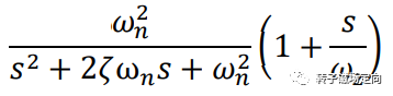
Simplifying the second-order system yields the following equation:
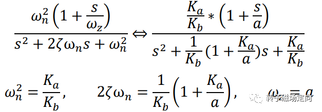
The bandwidth of the current loop, damping ratio, and zero point frequency are calculated as follows:

The results of the current loop PI calculation are as follows:

The above calculation process provided by Renesas is too complex. A simpler calculation process is to directly perform zero-pole cancellation on the poles of the denominator and the zero points of the numerator in the second-order system, reducing the transfer function directly to a first-order low-pass filter. The following calculation process can be referenced:
In the motor control system, if the switching frequency is set to 4k, how much bandwidth can the current loop achieve in Hz? – Zhihu (zhihu.com)
Speed Loop
The speed loop is modeled based on the mechanical characteristics of the motor. Ignoring the load torque, the motion equation of the motor can be simplified as follows:
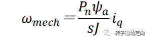
The expression for electromagnetic torque is as follows:

Then the mechanical speed can be expressed as:
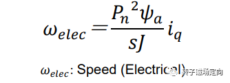
The electrical speed expression is as follows:
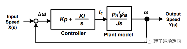
Taking the motor speed as the control object, ignoring the delay of the current loop, a control model of the speed loop is established, adding a PI series correction link:
Then the closed-loop transfer function of the speed loop is:
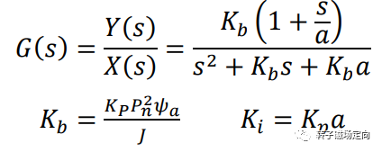
This transfer function cannot achieve zero-pole cancellation like the current loop, so the parameters are tuned according to the second-order system.
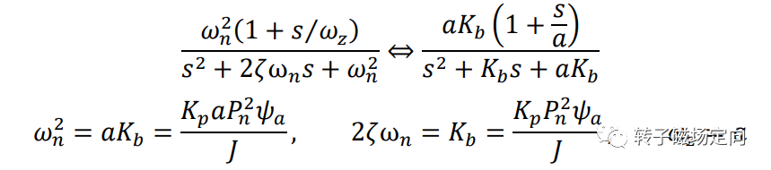
Through the second-order system, the tuning parameters yield the natural frequency, damping ratio, and zero point frequency:

The parameters of the speed loop are as follows:
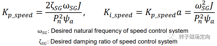
Among them, the bandwidth of sensorless FOC is generally taken as 5 to 20 Hz, and the damping ratio is taken as around 0.5.
Weak Magnetic
The implementation of weak magnetic is relatively simple, directly calculated through the voltage equation. In steady state, ignoring the current differential term, the given current Id can be calculated directly through steady-state voltage:

This method of calculation may not be very accurate, as it calculates based on steady-state current and does not have a weak magnetic control loop. In addition, it is necessary to know magnetic flux, otherwise it cannot be calculated.
The next article will analyze Renesas’s sensorless position estimation and the overall structure of FOC. Thank you for reading.
About the Author:
How do motor control engineers earn high salaries?
My house-buying story
What does a monthly salary of 40,000 RMB feel like?
Is it difficult to earn 100,000 a month?
Professional Articles:
Does Texas Instruments C2000 still have a market?
2022 Development Trends in the Electric Control Industry
FOC Learning Pitfall Guide
Sensorless FOC Control for Model Aircraft Based on M0 MCU
How powerful is MATLAB?
Nonlinear Observer Based on Magnetic Flux Model