 Introduction: PLC – The “Nervous Center” of Industrial AutomationIn the modern industrial system, the Programmable Logic Controller (PLC) is hailed as the “nervous center of industrial equipment”. Its core function is similar to that of an intelligent control system in a car: just as a driver conveys commands to the car through the steering wheel and accelerator, the car’s ECU coordinates the operation of components such as the engine and brakes based on preset logic. The PLC receives real-time signals from sensors (such as temperature, pressure, and position) and drives actuators (such as motors and solenoid valves) to achieve precise control after internal program calculations. This closed-loop capability of “perception-decision-execution” makes the PLC the core control unit of industrial automation production lines, widely used in key areas such as manufacturing, energy, and transportation.As the physical carrier of this core function, Mitsubishi PLCs exhibit a professional design unique to industrial equipment. Taking the FX3U-16M model as an example, it features a light gray rectangular shell with an integrated heat dissipation grille on the top to ensure stable operation over long periods. The left side of the front panel clearly displays the “MITSUBISHI” brand logo and the “FX3U-16M” model information, while the right side has a status indicator area with four indicator lights for “POWER”, “RUN”, “ERROR”, and “E.A.T” that provide real-time feedback on the device’s operating conditions. The bottom left is equipped with a round interface and a “RUN/STOP” mechanical switch for quick mode switching, reflecting the rigor and reliability of industrial control equipment.
 Core Feature Summary: As the core of industrial automation, the physical design of the PLC must meet three major requirements – stability (heat dissipation grille, engineering plastic shell), monitorability (multiple status indicator lights), and operational convenience (mechanical switch), all of which ensure continuous and reliable operation in industrial environments. The Mitsubishi MELSEC series PLCs (such as FX3U, FX5U, FX2N, etc.) not only represent typical industrial control solutions through standardized hardware architecture and modular design but also establish a complete control solution from small devices to large production lines, laying the hardware foundation for analyzing the functions and applications of soft components X/Y/M.
 1Analogous to Automotive Control Systems: The “Division of Labor and Cooperation” of Soft ComponentsThe precise cooperation mechanism of automotive electronic control systems provides an intuitive analogy for understanding the division of labor among PLC soft components. In automotive systems, the classic architecture of SENSOR → ECU → ACTUATOR corresponds highly with the working mode of PLC, which is Input Soft Component X (Information Collection) → Internal Logic Program (Processing Core) → Output Soft Component Y (Instruction Execution). This logic of “each performing its role while working together” is particularly clear in the layered network architecture of automobiles.
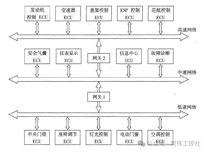 This architecture achieves functional division through three levels: the high-speed network connects core power units such as engine control ECU and transmission ECU, responsible for real-time transmission of critical control signals; the medium-speed network integrates body systems such as airbags and instrument displays, achieving status monitoring and information exchange; while the low-speed network manages auxiliary functions such as central locking and lighting control, forming a clearly defined collaborative system. Each level achieves bidirectional data transmission through gateways, similar to how signals collected by the X component in a PLC are processed by the internal program and then drive external devices through the Y component, maintaining module independence while ensuring overall collaboration.Specifically, the electrical principles of the automotive door control system further confirm this division of labor logic: the fuse box (power supply wiring) provides stable power, equivalent to the PLC’s power supply system; the unlocking relay and body control module (BCM) receive sensor signals and output control instructions, corresponding to the PLC’s X input and program processing stages; the four door actuator motors (LF/RF/LR/RR) act according to the output from the BCM, just like the Y component drives external loads. The wires marked with color, cross-section, and numbering (e.g., “0.8 brown-yellow 694”) are analogous to the internal data bus of the PLC, ensuring precise and orderly signal transmission.Core Analogous Relationships
-
Automotive Sensors (e.g., Air Flow Meter) → PLC Input Soft Component X (Signal Collection)
-
Automotive ECU (e.g., BCM, HEV ECU) → PLC Internal Logic Program (Signal Processing)
-
Automotive Actuators (e.g., Door Motors, Fuel Injectors) → PLC Output Soft Component Y (Instruction Execution)
The system architecture of hybrid vehicles further highlights the complexity of this collaboration: the HEV ECU serves as the core control module, connecting to “sensor-level” inputs such as the accelerator pedal and braking system on the left, while driving motors and generators through the Power Control Unit below as “actuator-level” outputs, and simultaneously achieving information exchange with other systems through gateways. This modular design parallels the division of labor among the X, M, and Y components in PLCs, both achieving precise control of complex systems through a mechanism of “layered responsibility and collaborative response”.2Detailed Explanation of Soft Components: Role Descriptions of X, Y, and M
Input Soft Component X: The “Eyes and Ears” of the PLC
Input Soft Component X serves as the core interface for the PLC’s interaction with the external world, functioning similarly to the human “eyes” and “ears” – by receiving signals from external sensors, buttons, switches, etc., it converts the state of the physical world into electrical signals recognizable by the PLC. In industrial control systems, external input devices such as limit switches (e.g., SQ1, SQ2), buttons (e.g., SB), and time relays (e.g., KT) are connected to the X soft component via terminal blocks for real-time signal collection.For example, when the external button SB is pressed, the corresponding X terminal (e.g., X0) detects the signal change and transmits that state to the PLC for logical processing.
Input Types: Differences Between Sinking and Sourcing Circuits
Based on the direction of current flow, the input circuit of the X soft component is divided into sinking input and sourcing input, with the core difference being the relationship between the signal current and the flow direction at the X terminal:
-
Sinking Input: Current flows out from the X terminal and must be used with NPN open-collector sensors. In the circuit, the positive terminal of the DC 24V power supply is connected to the X terminal through external devices, and the current flows into the PLC through the X terminal and returns to the negative terminal of the power supply via the common terminal (S/S). The typical circuit structure includes an NPN transistor symbol, with the current direction arrow clearly marked as “flowing out of the X terminal”.
-
Sourcing Input: Current flows into the X terminal and must be used with PNP open-collector sensors. Its circuit structure is similar to that of sinking input, but the current direction is reversed – the positive terminal of the power supply enters the PLC through the common terminal (S/S) and then flows out from the X terminal to external devices, ultimately returning to the negative terminal of the power supply. The circuit includes a PNP transistor symbol, with the current direction arrow marked as “flowing into the X terminal”.
The circuit principles of the two input types can be visually displayed through comparative diagrams: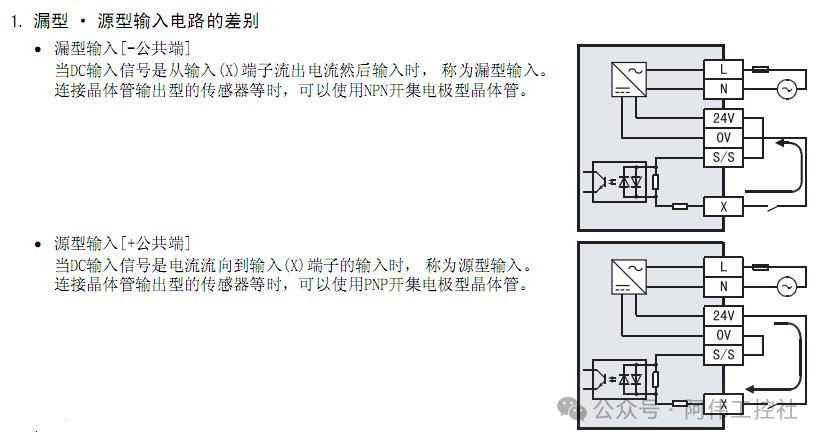
Numbering Rules: Octal Grouping of Terminal Arrangement
The numbering of the X soft component in Mitsubishi PLCs follows the octal rule, meaning each terminal group contains 8 input points (X0-X7), with subsequent groups starting from X10 (instead of X8), sequentially X10-X17, X20-X27, etc. This numbering method is consistent in hardware terminals and software programming; for example, the input terminals of the FX2N series PLC are labeled from left to right as X0, X1, X2, X3, X4 (the first five terminals of the first group), while the extended group starts with X10.Note: In octal numbering, there are no numbers X8 or X9, and writing “X8” by mistake during programming will result in a syntax error. When wiring, it is necessary to confirm the correspondence between the physical interface and the soft component numbering based on the terminal block markings (e.g., “IN area 0-7 and 10-17”).The typical arrangement of input terminals is shown in the diagram, clearly displaying the wiring relationship between terminals X0-X4 and external devices, as well as the layout of the COM common terminal: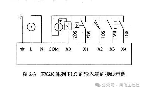 On the software side (e.g., GX Developer), the X soft component is represented in the form “X+number” (e.g., X0, X10), and its numbering must strictly correspond to the hardware terminals; otherwise, signal collection will fail.Through standardized design of input types and numbering rules, the X soft component of Mitsubishi PLCs achieves efficient and reliable access to external signals, laying the foundation for the execution of industrial control logic.3Output Soft Component Y: The “Hands and Muscles” of the PLCIn the control system of Mitsubishi PLCs, the output soft component Y undertakes the core function of the execution layer, equivalent to the “hands and muscles” of the PLC – when the CPU (the “brain”) generates control instructions through program logic, the Y component converts these digital signals into physical actions that drive external devices, achieving precise control over actuators such as motors, lights, and valves.
Driving Principle: Conversion from Digital Signals to Physical Actions
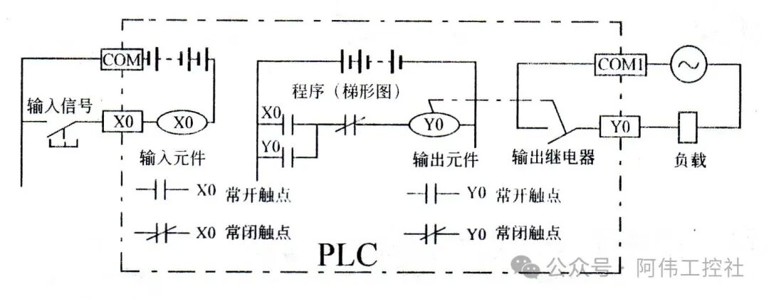
The core role of the Y component is to build control loops through output relays. In ladder diagram programs, Y usually exists in the form of output coils (e.g., Y000, Y002) or instruction control objects (e.g., SET/Y001, RST/Y001). When the program conditions are met, the corresponding internal relay coil of Y is energized, and its normally open contact closes, thus connecting the external load circuit.For example, in the case of relay output types, the Y component forms a loop with the external power supply and load through the common terminal (e.g., COM1): when the internal relay corresponding to terminal Y0 is activated, current flows from the COM1 common terminal to the load (e.g., motor), driving the device to start; when the relay resets, the loop is broken, and the device stops running. This control method is widely used in scenarios such as motor start-stop and light on-off, reflecting the core control logic of PLC “program instruction → physical action”.Key Features: The output state of the Y component is strictly controlled by the program, and it only acts when the output coil or instruction conditions in the ladder diagram are met. It also possesses instantaneous response and state holding capabilities (e.g., the SET instruction can keep Y in a powered state until the RST instruction resets it).
Numbering Rules: Octal Physical Interface Mapping
Similar to the input soft component X, the numbering of the output soft component Y also follows the octal rule and corresponds one-to-one with the PLC physical terminals. For example, in the FX2N series PLC, the output terminal area is arranged in the order of “Y0-Y7” and “Y10-Y17”, with no Y8 or Y9 decimal numbering. This design is consistent with the 8-bit byte addressing method of PLC internal registers.In the physical terminal layout, output interfaces are usually divided into multiple groups, each containing several Y terminals and a common terminal (e.g., COM1, COM2). For instance, Y0-Y7 corresponds to COM1, and Y10-Y17 corresponds to COM2. This grouping design can accommodate different voltage types of loads (e.g., AC220V, DC24V).In programming software such as GX Developer, the numbering of Y components must strictly correspond to the physical terminals (e.g., Y0 in software corresponds to the Y0 interface on the terminal block); otherwise, it will lead to a disconnection between control logic and actual actions.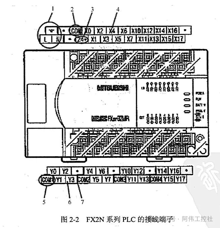
Typical Applications and Precautions
The output capability of the Y component is limited by the hardware type: relay output types (e.g., FX2N-32MR) are suitable for AC loads, with slower response speeds but strong load capacity; while transistor output types are suitable for high-frequency action scenarios (e.g., pulse control of stepper motors). When wiring, it is important to match the common terminal with the load power supply; for example, if the relay output Y terminal is connected to an AC220V load, the COM terminal must be connected to the AC220V neutral line; otherwise, an effective loop cannot be formed.In summary, the output soft component Y achieves physical intervention in industrial sites through the three-layer logic of “program control – relay action – load drive”, serving as a key bridge connecting the digital world and the physical world in automation systems. Its strict correspondence between numbering rules and physical interfaces further ensures the reliability and maintainability of control logic.4Auxiliary Soft Component M: The “Short-Term Memory Cells” of the PLCThe auxiliary soft component M plays a role similar to that of short-term memory cells in the brain within the PLC control system. Its core function is to temporarily store intermediate states during logical operations, achieving dynamic connections and timing control between input signals (X) and output signals (Y). This “temporary memory” characteristic allows M to store instantaneous signals in complex control processes and coordinate interactions among multiple modules, thus resolving potential logical conflicts or timing disorder that may arise from direct connections between inputs and outputs.
Typical Application Case: Temporary Storage and Transmission of M0 Signal Triggered by X0
For example, in a control scenario triggered by button X0, when the external sensor or operation button X0 generates an input signal, M0 can serve as an intermediate medium to temporarily store that signal state and drive subsequent execution components (e.g., timer T0). The specific logical flow is as follows: the rising edge signal of X0 triggers M0 to set, and after the normally open contact of M0 closes, it starts timer T0. Once T0 completes its timing, its normally open contact closes to drive output Y0 to act. During this process, M0 not only isolates the instantaneous fluctuations of the input signal but also ensures the stability of the timer start signal through its state-holding function, preventing control failure due to brief interruptions in the X0 signal.
Logical Implementation of M Soft Component in Ladder Diagrams
In ladder diagram programming, M soft components are typically implemented through pulse instructions for precise signal capture and logical switching. Common applications include:
-
Falling Edge Pulse Control (M0): Triggering M0 action at the moment the input signal X0 disconnects through the PLF (falling edge detection) instruction, with its normally open contact used to control logic that needs to execute when the signal disappears (e.g., equipment shutdown protection).
-
Rising Edge Pulse Control (M1): Triggering M1 action at the moment the input signal X1 connects through the PLS (rising edge detection) instruction, with its normally open contact suitable for scenarios requiring a single trigger (e.g., counter reset, alarm signal trigger).
This pulse-triggering mechanism allows M soft components to respond precisely to edge changes in signals rather than continuous states, effectively reducing invalid calculations and improving control accuracy.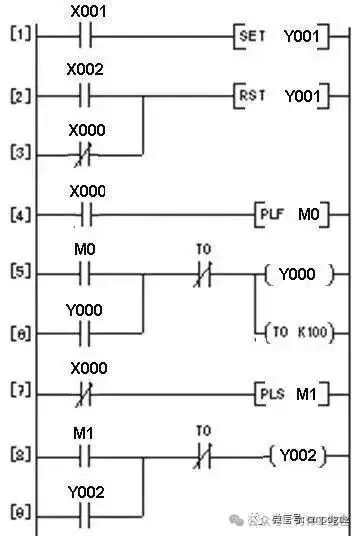 Key Feature Summary1.State Storage Medium: Isolates fluctuations in input signals from output execution needs, avoiding logical conflicts caused by direct connections.2.Pulse Signal Bridge: Achieves signal edge detection through PLS/PLF instructions, expanding the timing control dimension.3.Logical Modular Carrier: A single M soft component can be associated with multiple input-output modules, simplifying the programming implementation of complex control processes.Through these functional characteristics, the auxiliary soft component M significantly enhances the flexibility and reliability of the PLC control system, becoming a key “neural node” connecting the input perception layer and the output execution layer.5Octal Numbering Rule: The “Identity ID” of Soft ComponentsThe octal numbering rule of Mitsubishi PLC soft components is a typical reflection of the deep coupling between its hardware architecture and logical design. This rule can be traced back to the design logic of early hardware modules – input-output modules generally adopted a physical division method of 8 points per group, which directly determined that the software-level numbering system must follow the octal counting rule. In practical applications, this rule manifests as a continuity jump in terminal numbering: when a group of 8 terminals (e.g., X0-X7) is completed, the next group of terminals will directly start from X10, rather than the decimal logic of X8. This characteristic of “skipping 8-9” is an intuitive reflection of the essence of octal counting “every 8 counts as 1”.To help understand this abstract rule, a “floor numbering” analogy can be used: consider each group of 8 terminals as a “floor”, where the 1st floor contains rooms numbered 0-7 (corresponding to X0-X7), and the 2nd floor starts from room number 10 (corresponding to X10-X17), and so on. This numbering method not only ensures a one-to-one correspondence between hardware terminals and software addresses but also maximizes the utilization of the limited address coding space of early PLCs.
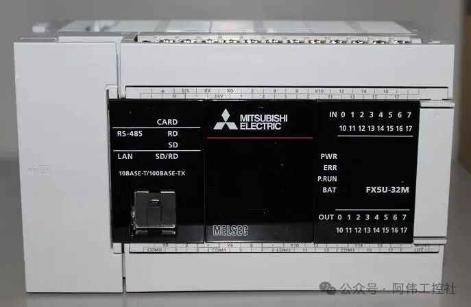 From the perspective of physical terminal layout, typical Mitsubishi PLCs’ input (IN) and output (OUT) areas strictly follow this rule. For example, the IN area of a certain device is clearly marked as two groups of numbers 0-7 and 10-17, and the OUT area also adopts the numbering sequence of 0-7 and 10-17, with neither 8 nor 9 appearing in these two groups, directly confirming the implementation of octal counting at the hardware level.In specific models, taking the FX2N series PLC as an example, the numbering system of input soft component X and output soft component Y fully presents the application of the octal rule: the input terminal numbering sequence of X is X0, X1, X2, X3, X4, X5, X6, X7, X10, X11, X12, X13, X14, X15, X16, X17, and the output terminal numbering sequence of Y is Y0, Y1, Y2, Y3, Y4, Y5, Y6, Y7, Y10, Y11, Y12, Y13, Y14, Y15, Y16, Y17. In these numberings, there are absolutely no numbers 8 or 9, and each group of numbers cycles through “0-7”, fully reflecting the core characteristics of octal counting “base 8, digit range 0-7”.Core Features of Octal Numbering
-
Hardware Origin: The division of modules into groups of 8 points determines the base of the numbering to be 8.
-
Numbering Pattern: Each group of terminals is arranged in the order of 0-7, with the next group starting from 10 (i.e., octal 10 corresponds to decimal 8).
-
Numbering Taboo: The numbers 8 or 9 must not appear in the numbering to avoid confusion with decimal.
-
Consistency: Both input X and output Y soft components follow the same numbering logic, ensuring the uniqueness of the soft and hardware address mapping.
Understanding this rule is crucial for PLC program design: engineers must strictly adhere to the octal numbering logic when writing logic to avoid address errors caused by habitual use of decimal thinking (e.g., mistakenly writing X8, Y9, etc. as illegal addresses). Additionally, when wiring, the correspondence between terminal numbering and soft component addresses in octal must be ensured to accurately match physical signals with logical signals.6Collaboration Example: How X, Y, and M “Work Together”In the Mitsubishi PLC control system, the collaborative work of input soft components (X), output soft components (Y), and auxiliary relays (M) is the foundation for achieving complex logical control. Taking the automatic door control as a typical case, it clearly demonstrates the process of completing specific functions through signal transmission and timing coordination among the three. This case reflects the core logic of soft component collaboration through button triggering, signal storage, execution driving, and timed reset in a closed-loop control.7Case WorkflowWhen the operator presses the open door button, the input relay X0 receives the external signal and closes, generating an open door trigger signal. This signal is processed by the PLC internal program, first triggering the auxiliary relay M0 to achieve signal storage, ensuring stable transmission and logical isolation of the signal. After the normally open contact of M0 closes, it energizes the output relay Y0, and the external contact of Y0 controls the motor to execute the opening action. Simultaneously, the normally open contact of Y0 closes to start timer T0, setting the timing value to 3 seconds (corresponding to constant K30). When the T0 timing reaches completion, its normally closed contact opens, causing Y0 to lose power and reset, stopping the motor and completing a full open door control cycle.Signal Transmission Path: X0 (input signal) → M0 (signal storage) → Y0 (execution output) → T0 (timing control) → Y0 reset (stop output). This process achieves a complete control chain from external triggering to internal logical processing, and then to the action of external actuators.8Program Implementation and Soft Component CollaborationThe ladder diagram implementation of this control logic is shown in the diagram, mainly including the following key steps:
-
Signal Triggering and Storage: Ensuring M0 is triggered only when the X0 signal changes from on to off through the falling edge pulse instruction (PLF M0), avoiding continuous signal interference.
-
Output Driving and Timing Start: The normally open contact of M0 and the normally closed contact of T0 are connected in series to control the Y0 output coil, ensuring that Y0 is energized only when M0 is triggered and T0 has not acted; after the normally open contact of Y0 closes, T0 is started to achieve timing control.
-
Timing Reset Logic: When the T0 timing reaches completion, its normally closed contact opens, cutting off the driving loop of Y0, achieving automatic stopping of the motor. This design of “output driving timing – timing cutting off output” reflects the core idea of interlocking and timing coordination among soft components.
9Parameter Configuration and Timing AnnotationIn practical applications, key parameters need to be configured according to control requirements:
-
Timer T0: Set value K30 (in units of 100ms, corresponding to 3 seconds), ensuring the door has enough time to complete the opening action.
-
Auxiliary Relay M0: As an intermediate logical variable, it isolates input signals from output control, improving program reliability and maintainability.
-
Output Relay Y0: Must configure a suitable external driving circuit (e.g., contactor or inverter) based on motor power to achieve safe isolation of weak current control from strong current.
This case illustrates that X serves as the signal input interface, M as the intermediate layer in logical processing, and Y as the execution control output. Together with timers and other soft components, they form the core control unit of the PLC control system. This layered collaboration model not only simplifies program logic but also enhances the stability and scalability of the system, representing a typical paradigm of soft component application in industrial automation control.10Conclusion: Soft Components – The “Minimum Control Unit” of Industrial AutomationIn industrial automation control systems, X (input relay), Y (output relay), and M (auxiliary relay) serve as the core soft components of Mitsubishi PLCs, forming the “minimum control unit” for achieving logical control. These basic components are like the “standard building blocks” of industrial control, capable of constructing automation solutions ranging from simple start-stop control to complex timing logic through basic logical combinations of series, parallel contacts, and coil drives, providing foundational support for the precise operation of production lines. This modular design not only reduces the complexity of system development but also endows control programs with high flexibility and scalability, allowing engineers to quickly adjust control logic according to specific process requirements, achieving dynamic adaptation of production line functions.With the deepening of Industry 4.0 and smart manufacturing, PLC technology is evolving from traditional logical control to intelligent and networked directions. In future factories, soft components will deeply integrate into the Internet of Things (IoT) and artificial intelligence (AI) systems as foundational nodes for data collection and instruction execution: the production data collected in real-time by the X component can be uploaded to cloud platforms via edge computing nodes, combined with AI algorithms for predictive maintenance and process optimization; the Y component can implement adaptive adjustments of production equipment based on dynamic instructions from intelligent decision-making systems; while the M component, as an intermediate logical carrier, will undertake more complex state memory and data transfer functions, becoming a key bridge connecting the physical layer and the information layer. This technological integration not only expands the application boundaries of soft components but also promotes the upgrade of industrial control systems from “automation” to “autonomy”.Just as the precise operation of a car relies on the collaborative work of every component, the stability and reliability of industrial automation systems also depend on the precise coordination of X/Y/M soft components. Each soft component, while having a single function, plays an indispensable “part” role in the control system – input components are like the “sensors” of a car sensing the external environment, output components are akin to “actuators” driving mechanical actions, and auxiliary components are similar to “control logic units” coordinating the interaction of various systems. This rigor in underlying logic is the core of Mitsubishi PLC’s technological advantage in the field of industrial control and lays a solid foundation for the innovative development of future smart manufacturing.Core Insight: As the “atomic-level control units” of industrial automation, soft components’ value lies not only in their current logical control functions but also in providing an expandable underlying architecture for industrial digital transformation. In the future, as technological integration deepens, these basic components will become key carriers for achieving “intelligent control” and “data-driven” solutions. Scan to add WeChat and learn automation technology WeChat ID: T13147077956 Phone Number: 13147077956