With the rapid development of automotive electronics technology, the iteration of technologies such as new energy vehicles and autonomous driving is driving profound changes in the overall vehicle electronic architecture. The number of ECU controllers installed in vehicles has surged from dozens in traditional models to hundreds, and the number of various sensors (such as millimeter-wave radar and LiDAR) and actuators has also increased exponentially. Under this trend, the data transmission capacity of the traditional CAN bus has gradually become a key bottleneck restricting overall vehicle performance: although its maximum transmission rate can reach 1 Mbit/s, in practical applications in the automotive field, it is often limited to 500 Kbit/s due to factors such as electromagnetic compatibility, making it difficult to meet the high concurrency data throughput requirements of multiple nodes. The emergence of CAN FD (CAN with Flexible Data-rate) technology is precisely aimed at breaking through this bottleneck. It not only increases the data transmission rate to a maximum of 15 Mbit/s (typically 5 Mbit/s in practical automotive applications) but also expands the data length of each frame from the traditional 8 bytes to 64 bytes. This improvement brings significant efficiency gains: for example, in the identity authentication scenario of UDS (Unified Diagnostic Services) messages, the traditional CAN requires multiple messages to complete the verification process, while CAN FD can achieve this with a single long frame.
Frame Structure Comparison: Core Differences Between Traditional CAN and CAN FD
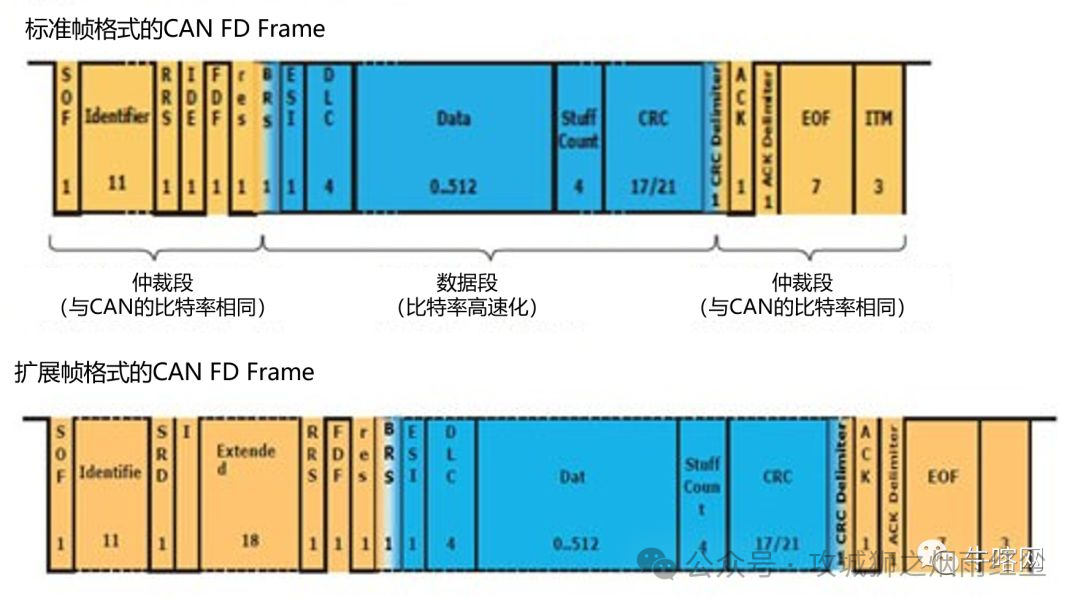
Both the frame structure of traditional CAN and CAN FD has both inheritance and innovation in its basic format. The following comparison of the structure of a 1-byte data frame visually demonstrates the key differences between the two (Figure 1):
1. Frame Start and Arbitration Field: Fully Compatible Basic Design
The frame start (SOF) and arbitration field structures of both are completely consistent, ensuring backward compatibility of CAN FD with traditional CAN nodes: Frame Start (SOF): Both consist of 1 dominant bit (logical 0), marking the start of frame transmission. Arbitration Field: Contains 11 bits of CAN ID and 1 bit of remote transmission request (in traditional CAN called RTR, in CAN FD called RRS). In the data frame, both RTR/RRS are 0, and in the remote frame, both are 1, avoiding bus conflicts through a dominant bit priority arbitration mechanism.
2. Control Field: Key Breakthrough in Flexibility and Expandability
The control field is the most significant part of the difference between the two, directly determining the improvement in data transmission capacity:
Parameter Traditional CAN CAN FD
Control Field Length: 6 bits 9 bits
IDE Bit: 0 (standard frame) 0 (maintain compatibility)
FDF Bit: 0 (R0 reserved bit) 1 (CAN FD frame format)
BRS Bit: None 0 = rate unchanged; 1 = data segment switches to high rate
ESI Bit: None 0 = normal state; 1 = sending node detects a serious error
DLC: Encoding Range 0-8 bytes (4-bit DLC directly corresponds to data length) 0-64 bytes (4-bit DLC extended through specific encoding, e.g., 1001=12 bytes, 1111=64 bytes)
Table: Comparison of Control Field Parameters Between Traditional CAN and CAN FD
Among them, the BRS bit (Bit Rate Switch) is the core to achieving “flexible data rate”: when BRS=1, the data field, CRC field, etc., after the BRS bit will be transmitted at a higher bit rate (e.g., arbitration segment at 1 Mbit/s, data segment at 5 Mbit/s). This design ensures compatibility during the arbitration phase while significantly improving data transmission efficiency.
3. Data Field and CRC Field: Dual Optimization of Reliability and Efficiency
Data Field: The maximum data length of traditional CAN is 8 bytes, while CAN FD extends it to 64 bytes, reducing the need for message fragmentation. CRC Field: To accommodate longer data frames, the CRC sequence length of CAN FD dynamically adjusts—when data length ≤ 16 bytes, it is 17 bits; when ≥ 20 bytes, it is 21 bits (traditional CAN is fixed at 15 bits), and adds 4 bits of Stuff Count, enhancing error detection capability.
4. Acknowledgment Field and Frame End: Compatible Closing Design
The structures of the acknowledgment field (ACK) and frame end (EOF) of both are completely consistent: the acknowledgment field consists of 1 acknowledgment bit and 1 acknowledgment delimiter, and the frame end consists of 7 dominant bits (logical 1), ensuring a consistent judgment of message reception status by bus nodes.
Performance Leap: Quantitative Comparison of Transmission Efficiency
The rate-switching mechanism of CAN FD has brought significant improvements in transmission efficiency. Taking a typical application scenario in the automotive field as an example:
Traditional CAN: All fields are transmitted at 500 Kbit/s, requiring about 190 µs for each frame of 8 bytes of data (including padding bits).
CAN FD: The arbitration segment is transmitted at 500 Kbit/s, and the data segment switches to 5 Mbit/s, requiring only about 190 µs for each frame of 64 bytes of data—achieving a breakthrough of “8 times the data volume in the same transmission time.” This efficiency improvement not only alleviates the bandwidth pressure on the bus but also reduces communication latency for ECUs, providing critical support for high real-time requirements such as autonomous driving.
Conclusion
CAN FD technology, through the two core improvements of “variable rate” and “data length extension,” perfectly adapts to the modern automotive electronics demand for high bandwidth and low latency communication while maintaining compatibility with traditional CAN. As the in-vehicle network evolves towards a zonal architecture, CAN FD will collaborate with protocols such as Ethernet and LIN to build a more efficient and reliable vehicle communication ecosystem.