Follow us for free subscriptions to the latest avionics news.

Abstract
The avionics large-size LCD display module is characterized by high brightness and high power consumption. To reduce its dynamic power consumption, a dynamic backlight control system for large-size avionics display modules is introduced. This system employs light-emitting diode (LED) dynamic backlight control technology, dynamically adjusting the backlight to enhance dynamic display effects and achieve energy-saving goals. A detailed introduction to the hardware circuit and software design algorithm of the system is provided, along with experimental verification. The results show that this system can effectively improve the dynamic display effect of avionics display modules and significantly reduce dynamic power consumption.
Keywords
Large size; avionics; off-axis two reflections; freeform surface; small F-number; XY polynomial

With the continuous advancement of aviation technology, the application of avionics display modules is becoming increasingly widespread and important, gradually developing towards large-size integration, high brightness, and intelligence. The traditional backlight control technology for LCD display modules uses a constant current driving method, employing a series and parallel arrangement of LED strips. Since all lamp strings are powered by a uniform voltage supply, all lamps are lit during operation, resulting in significant power waste. Additionally, due to the certain transparency of the LCD screen, the global backlight system also causes a decrease in dynamic contrast, reducing display effects. The display performance and energy-saving effects of avionics display modules have a significant impact on aircraft safety. Therefore, enhancing the display effect and reducing power consumption of avionics display modules has become an important research direction.
A design scheme for a dynamic backlight control system for large-size avionics display modules is introduced. This system independently controls the LEDs, with the luminous intensity of each LED determined by the display content of its corresponding display area, thus achieving dynamic adjustment of the backlight, improving the display effect of avionics display modules and reducing dynamic power consumption.

1 Control System Design
The system is applied to a large-size avionics display module, which uses a 9″×24″ LCD with a resolution of 3200×1200, requiring a brightness of 1000cd/m2 and a contrast ratio of no less than 1000:1, with power consumption less than 60W. To meet these technical requirements as much as possible, the system architecture shown in Figure 1 is designed.
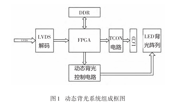
The main components of this system include: low-voltage differential signaling (LVDS) decoding circuit, FPGA, DDR3 (double data rate third generation), dynamic backlight control circuit, TCON (timing controller) control circuit, LCD, and LED backlight array. The LVDS decoding circuit decodes the user-input LVDS signals and inputs them into the FPGA for subsequent processing; the FPGA serves as the main control module of the entire system, implementing signal processing, video format conversion, and control of the TCON and LED control circuits; DDR3 is used for buffering input video data. Since it is necessary to count the brightness information of each LED, the entire frame data needs to be partitioned and counted. If the video data of a frame is not buffered, there will be a frame delay between the LED counting signals and the displayed video image, which can cause trailing and halo issues in dynamic image displays; the dynamic backlight control circuit controls the scanning of the backlight array and the transmission and control of backlight brightness data, allowing the LED array to dynamically adjust brightness based on the current display content; the TCON control circuit generates the voltage and gamma correction needed to drive the LCD, enabling the LCD to display video content correctly; each LED in the LED backlight array can be independently controlled. To reduce the complexity of the control system, a matrix scanning method is used to control the LEDs, providing high brightness and high contrast display effects.

2 Dynamic Backlight Control Circuit Design
The LED backlight array uses 0402 small package LED lights, and all LEDs are arranged in a matrix. Since the left and right sides of the LCD are independently controlled, the number of partitions on one side is 42 rows × 54 columns, so there are a total of 4536 partitions on the entire LED backlight panel.
With so many LED partitions, if each LED had an independent driving circuit for control, it would require a large number of components and cause additional power loss, which does not align with the goal of reducing power consumption. Therefore, a dedicated driver chip combined with matrix scanning is used to control each LED. The LED driver chip has 48 channels of independent pulse width modulation (PWM) control, with a maximum output current of 30A, maximum output voltage of 5V, maximum PWM dimming frequency of 30kHz, and maximum operating temperature of 125℃. It can communicate with the chip via SPI (serial peripheral interface), controlling the chip’s operating mode and the brightness value and driving current, keeping it in an ideal state. Additionally, this chip has various protection features, such as overcurrent and overtemperature protection, effectively safeguarding the safe and stable operation of the LED display. These performance indicators enable the chip to meet the requirements of the avionics environment. The architecture of the LED array driver circuit is shown in Figure 2.
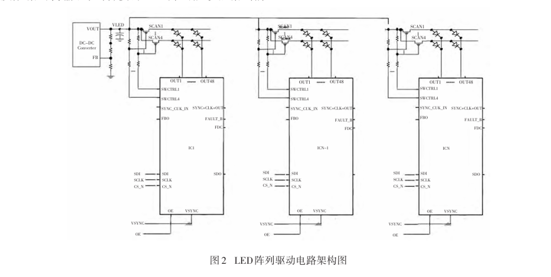
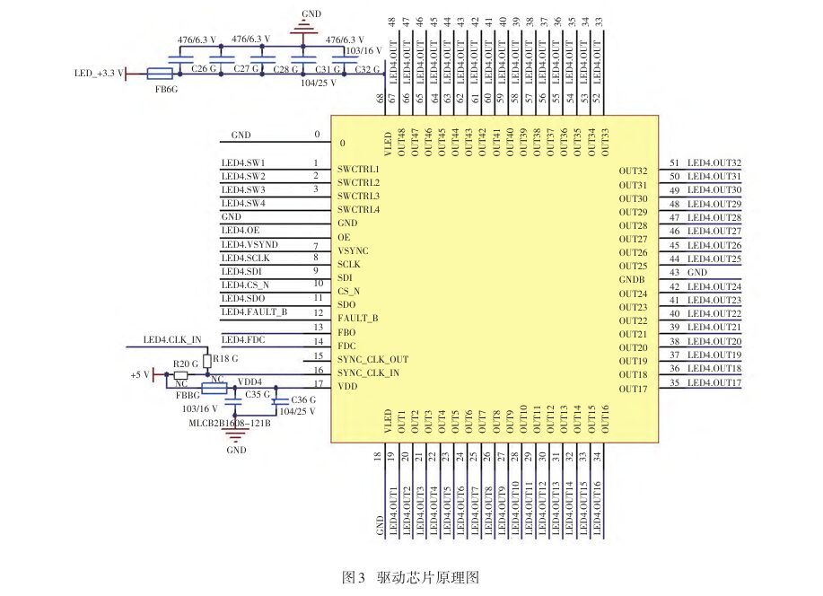
Each chip can control a maximum of 48×4 LEDs, so the system requires 4536/(48×4)=24 chips, adopting the driver architecture shown in Figure 2. The 24 chips operate independently, with each chip corresponding to 4 PMOS as row selection switches, controlling 48 LEDs at a time. The brightness data of each LED is transmitted to the chip via GNDSPI. Independent control can improve the refresh speed, but requires independent control signals. Since the selected FPGA has sufficient IO pins, it meets the control requirements. The schematic diagram of a single chip is shown in Figure 3.

3 Control Algorithm Implementation
The main controller of the control system is the FPGA, which mainly extracts backlight brightness data, processes video signals, converts video signal formats to drive the LCD display, maps brightness data, initializes and configures the backlight driver chip, and controls brightness to drive the backlight. The architecture diagram of the internal modules of the FPGA is shown in Figure 4.
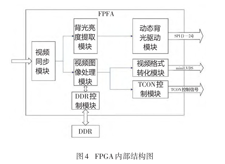
The video synchronization module achieves synchronization between the external video clock domain and the internal video working clock domain, allowing data processing to occur within a single clock domain to avoid timing issues. The video processing module completes processing of video contrast, gamma correction, etc., ensuring that the video output to the LCD achieves optimal display quality. To match the LED backlight brightness with the video display content, DDR buffering is used to synchronize LED analysis data and video data. Since the LCD uses a miniLVDS interface, the internal RGB signals need to be converted according to miniLVDS format requirements to ensure the LCD can receive and display correctly. The TCON control module generates the timing signals required to drive the LCD, allowing miniLVDS signals to be displayed correctly on the LCD array. The backlight brightness extraction module uses a maximum value extraction algorithm to calculate the maximum gray value of the red pixel R, green pixel G, and blue pixel B for each corresponding position of the LCD screen sub-region on the dynamic backlight panel, writing the calculated maximum gray value data into random access memory (RAM). After a frame of images is written, the dynamic backlight driver module reads brightness data from RAM and writes it to the backlight driver chip and control signals via the SPI bus. Since the focus of this article is on the design of dynamic backlighting and video processing, the content related to the TCON control module will not be detailed, mainly focusing on the brightness extraction and dynamic backlight control modules.
3.1 Backlight Brightness Extraction Module
(1) Sub-region Pixel Matrix Division
Since the LED brightness of the dynamic backlight is determined by the current display video content, each LED controls a rectangular area, the size of which is i (in column direction) and j (in row direction), related to the LCD screen resolution and backlight array size. The pixel matrix of the LCD screen is divided into sub-region pixel matrices based on the effective resolution size of horizontal pixels H_size × vertical pixels V_size, with the LED matrix divided into N rows × M columns for each sub-region pixel matrix, as shown below:
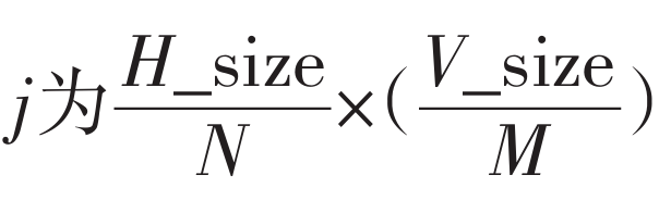
If it cannot be evenly divided, it can be allocated based on the actual number of lamps. The designed display resolution is 1600×1200, and the backlight lamp matrix is 54×42=2268. According to the calculation, the size of the sub-region pixel matrix is 29.6×28.5, rounded to i×j=30×29, totaling 2268 sub-region pixel matrices.
(2) Maximum Value Extraction Algorithm
The designed brightness extraction algorithm uses the maximum value method, as follows:

That is, the maximum value among the RGB gray values in the i×j pixel matrix of the sub-region is extracted as the reference value for the backlight brightness data.
In the FPGA implementation: to save internal logic resources, 54 registers maxn (0≤n≤53) are defined in the FPGA to count the maximum value among the 54 regions in a row of data. Meanwhile, by counting in the row and column directions using DEN, when i≤hcnt≤30i, j≤vcnt≤29j corresponds to the (i,j) region. Here, hcnt is counted while DEN is high, and vcnt counts at the falling edge of DEN. When vcnt=29j and hcnt=30i, each maxn is written to subsequent modules. When vcnt=29j and hcnt=1599, all maxn are reset to prepare for the next maximum value calculation. The architecture of the algorithm is shown in Figure 5.
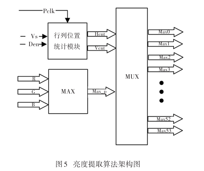
The entire module’s inputs are pixel clock PCLK, field synchronization VS, data valid identifier Den, and video data RGB values. To simplify logic, the maximum value extraction of the input RGB data is performed, and then under the control of hcnt and vcnt, the output maximum value max_p is compared with the corresponding region’s maxn. If max_p>maxn, max_p is assigned to maxn until all data in the region are compared. Then maxn is output one by one, generating an enable signal to output to the backend module.
3.2 Dynamic Backlight Driver Module
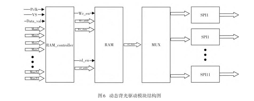
The dynamic backlight driver module mainly initializes the backlight driver chip, outputs control signals, and updates brightness data in real-time through the SPI bus. The design includes 12 SPI bus drives. These 12 SPI buses work in parallel, initializing and configuring 12 backlight driver chips, outputting control signals, and updating brightness data. Each driver chip controls 48×4=192 LEDs. Taking one SPI driver as an example, the other 11 operate on the same principle.
After powering on the FPGA system, control signals are output to the backlight driver chip, and the driver chip is initialized through the SPI bus by configuring the registers. The initial brightness data is set to 0, ensuring that the brightness value is 0 during startup. For convenience, a RAM is opened in the FPGA to store the brightness values of each region output by the backlight brightness extraction module for subsequent operations.
After the backlight driver chip is initialized, brightness data configuration begins. To ensure that the brightness data receiving module’s RAM updates are complete, RAM data is read after the update. At the rising edge of VS, RAM read addresses are generated, and data is read from RAM, writing it into the corresponding address register of the backlight driver chip through the SPI bus to update the brightness values, completing brightness adjustments for different display regions. The structure of the dynamic backlight driver module is shown in Figure 6.
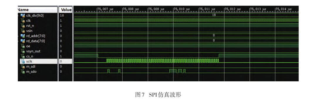
The SPI module directly controls the backlight control chip, and its reliability and control speed directly determine whether the system’s functions can be realized. This module has the highest quantity, occupying the most resources, and thus requires special attention for its implementation. The SPIX4 mode is used to control the backlight chip, achieving a high refresh rate. The simulation waveform of the SPI control module is shown in Figure 7.

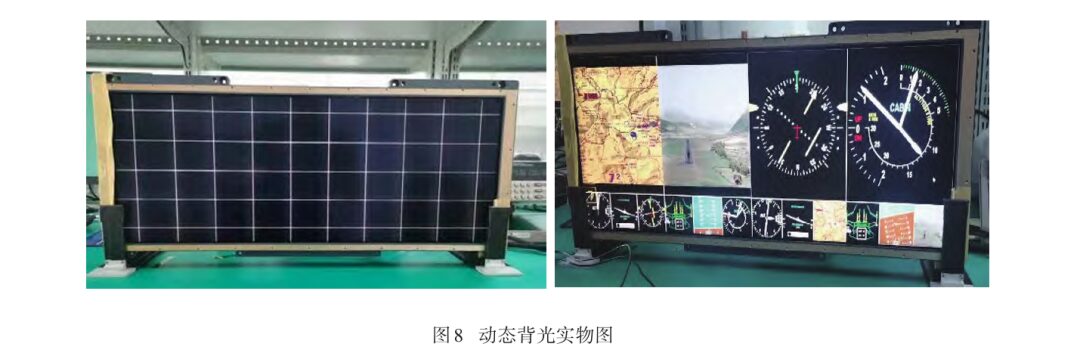
4 System Implementation Effects
According to the above design scheme, a dynamic backlight system for large-size LCD modules was produced. Figure 8 shows the actual dynamic backlight, demonstrating that the above design can achieve the corresponding dynamic backlight function. Experiments and tests were conducted on the actual product and traditional backlight products, with experimental data shown in Table 1.
(Article excerpted from “Optics and Photonics Technology” by Wu Chao, Yang Lihong, Zhao Chenxi, Li Minmin, Zhang Jingjing, affiliated with the School of Optoelectronic Engineering, Xi’an University of Technology. This article is reprinted solely for the purpose of disseminating knowledge. If there are any copyright issues, please contact us promptly!)