The Concept of Queue
Before we start, let’s review the basic concept of a queue:
Queue: A linear structure that follows the First In First Out (FIFO) principle, allowing insertion at one end (enqueue) and deletion at the other end (dequeue).
Characteristics of a Queue
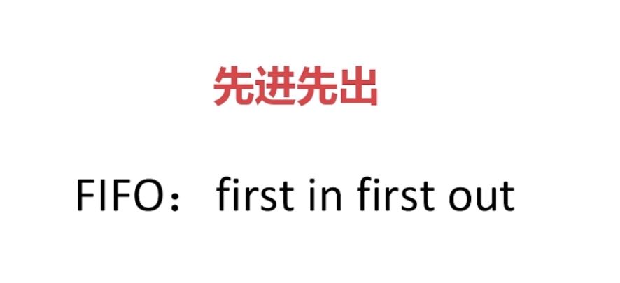
 Similar to a ticket queue, the first person to arrive gets to buy the ticket first and leaves, while later arrivals have to wait.

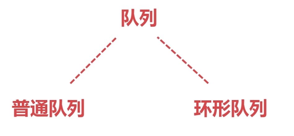

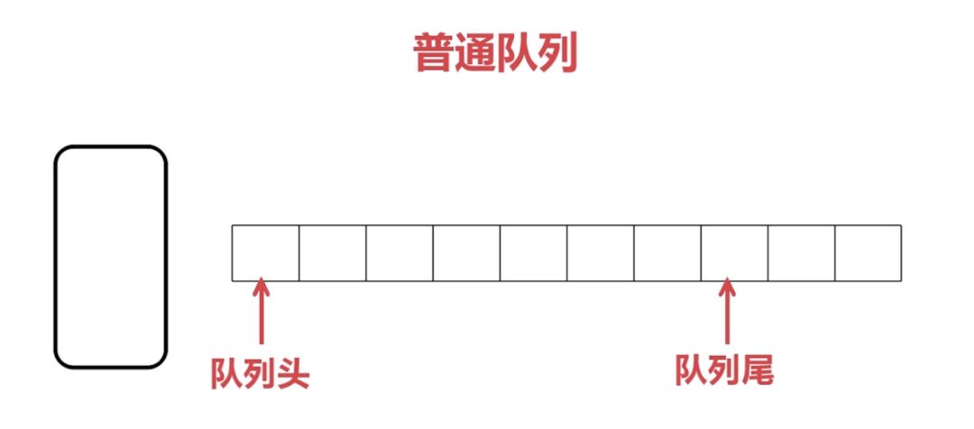
In computers, every piece of information is stored in memory cells. Imagine the small squares in the above image as memory cells, similar to a common array, where we store individual pieces of information.
When there is a large amount of data, we cannot store all of it. Therefore, when the computer processes data, it can only handle the incoming data sequentially. Once processed, the data is released, and the next one is handled. However, the memory of already processed data would be wasted. Since later data can only queue behind, moving all remaining data forward would be inefficient and impractical, leading to the need for a circular queue.

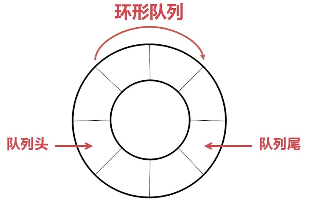
Its queue forms a circle, avoiding the drawbacks of an ordinary queue, which can be a bit challenging to understand. In fact, it is still a queue, with a head and a tail, and follows the FIFO principle.
Queue Head (Head): The end where deletion occurs is called the queue head.
Queue Tail (Tail): The end where insertion occurs is called the queue tail.
Implementation of Circular Queue: In computers, there is no circular memory. Instead, we manipulate sequential memory to create a circular structure, connecting the ends together, which can be simply understood as an array with two pointers, one pointing to the queue head and the other to the queue tail. The pointer to the queue head (Head) represents the data that can be read from the buffer, while the pointer to the queue tail (Tail) represents the data that can be written to the buffer. By moving these two pointers (Head) &(Tail), we can perform read and write operations on the buffer until it is full (head and tail meet). Once the data is processed, it can be released, allowing new data storage.
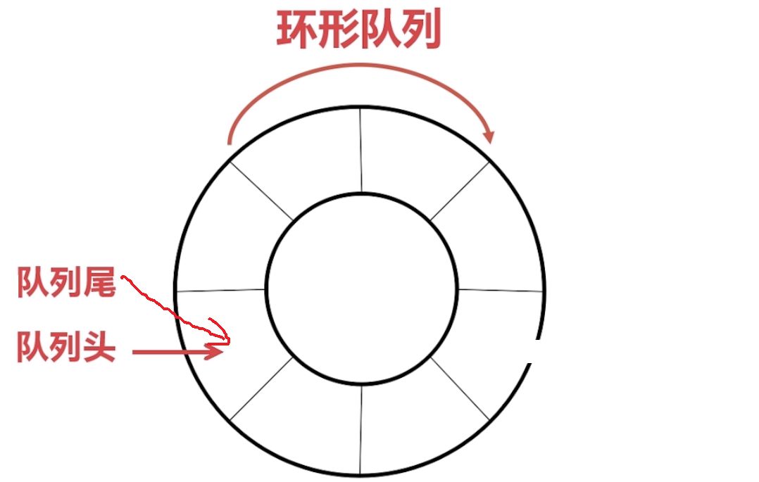
The principle of implementation: When initialized, both the queue head and tail point to 0. When data is stored, it is placed in the address space of ‘0’, and the queue tail points to the next available storage location ‘1’. When more data arrives, it is stored at address ‘1’, and the queue tail points to the next address ‘2’. When processing data, the first data in the ‘0’ space (the queue head data) is processed first. Once processed, the data in the ‘0’ address space is released, and the queue head points to the next address ‘1’. This way, the entire circular buffer can read and write data.
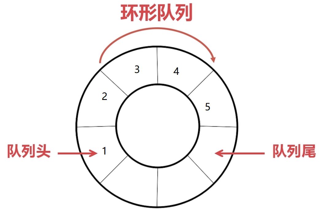
As shown in the diagram, the queue head points to the data that has been stored and is waiting to be processed. The next data to be processed by the CPU is ‘1’; the queue tail points to the address where data can be written. Once ‘1’ is processed, it will be released, and the queue head will point to ‘2’. When a new data ‘6’ is written, the queue tail pointer will point to the next writable address.
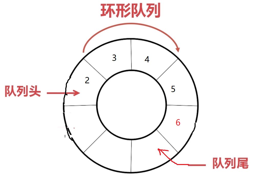
If you understand the circular queue, let’s follow along with the code implementation step by step:

UART Circular Buffer Transmission: In many beginner tutorials, we learn that UART transmission involves receiving one piece of data, triggering an interrupt, and then sending the data back. This method lacks buffering, and when the data volume is too large or received too quickly, we may not be able to process the already received data in time. Consequently, when new data arrives, it may overwrite the unprocessed data, leading to data loss, which can be critical for our program.
So how can we prevent this situation? Clearly, the characteristics of the queue mentioned above can easily help us achieve our needs. We can buffer the incoming data, allowing processing speed to catch up with the receiving speed. As analyzed earlier, we will definitely use a circular queue for implementation. The following is the code implementation:
① Define a structure:
1typedef struct
2{
3    u16 Head;
4    u16 Tail;
5    u16 Length;
6    u8 Ring_Buff[RINGBUFF_LEN];
7}RingBuff_t;
8RingBuff_t ringBuff;// Create a ringBuff buffer
② Initialize the structure related information: This ensures our circular buffer is connected head to tail and starts empty.
 1/**
 2* @brief  RingBuff_Init
 3* @param  void
 4* @return void
 5* @author Jie Jie
 6* @date   2018
 7* @version v1.0
 8* @note   Initialize circular buffer
 9*/
10void RingBuff_Init(void)
11{
12   // Initialize related information
13   ringBuff.Head = 0;
14   ringBuff.Tail = 0;
15   ringBuff.Length = 0;
16}
Initialization effect as follows:
Code implementation for writing to the circular buffer:
 1/**
 2* @brief  Write_RingBuff
 3* @param  u8 data
 4* @return FALSE: Buffer full, write failed; TRUE: Write successful
 5* @author Jie Jie
 6* @date   2018
 7* @version v1.0
 8* @note   Write u8 type data to circular buffer
 9*/
10u8 Write_RingBuff(u8 data)
11{
12   if(ringBuff.Length >= RINGBUFF_LEN) // Check if buffer is full
13    {
14      return FALSE;
15    }
16    ringBuff.Ring_Buff[ringBuff.Tail]=data;
17//    ringBuff.Tail++;
18    ringBuff.Tail = (ringBuff.Tail+1)%RINGBUFF_LEN;// Prevent out-of-bounds access
19    ringBuff.Length++;
20    return TRUE;
21}
Code implementation for reading data from the buffer:
 1/**
 2* @brief  Read_RingBuff
 3* @param  u8 *rData, used to store the read data
 4* @return FALSE: Buffer empty, read failed; TRUE: Read successful
 5* @author Jie Jie
 6* @date   2018
 7* @version v1.0
 8* @note   Read a u8 type data from circular buffer
 9*/
10u8 Read_RingBuff(u8 *rData)
11{
12   if(ringBuff.Length == 0)// Check if not empty
13    {
14       return FALSE;
15    }
16   *rData = ringBuff.Ring_Buff[ringBuff.Head];// FIFO, read from buffer head
17//   ringBuff.Head++;
18   ringBuff.Head = (ringBuff.Head+1)%RINGBUFF_LEN;// Prevent out-of-bounds access
19   ringBuff.Length--;
20   return TRUE;
21}

There are two important points to note regarding read and write operations:
1: Check if the queue is empty or full. If empty, reading data is not allowed, and it returns FALSE. If full, writing data is not allowed to avoid overwriting existing data. If processing speed cannot keep up with the receiving speed, consider increasing the buffer size to trade space for time.
2: Prevent out-of-bounds access. The user must be aware of the total size of the buffer.

In the UART receive function:
1void USART1_IRQHandler(void)
2{
3   if(USART_GetITStatus(USART1, USART_IT_RXNE) != RESET)  // Receive interrupt
4                   {
5           USART_ClearITPendingBit(USART1,USART_IT_RXNE);       // Clear flag
6           Write_RingBuff(USART_ReceiveData(USART1));      // Read received data
7       }
8}

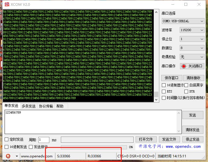
No data loss occurred during testing

At this stage, I, Jie Jie, have slowly learned to standardize my coding. All code snippets use highly readable and portable formats. I used macro definitions to decide whether to enable the circular buffer for data transmission, which can be easily integrated into everyone’s code without side effects—just enable the macro definition to use it.
 1#define USER_RINGBUFF  1  // Use circular buffer for data reception
 2#if  USER_RINGBUFF
 3/** If using circular buffer for UART data reception **/
 4#define  RINGBUFF_LEN          200     // Define maximum reception byte count 200
 5#define  FALSE   1
 6#define  TRUE    0
 7void RingBuff_Init(void);
 8u8 Write_RingBuff(u8 data);
 9u8 Read_RingBuff(u8 *rData);
10#endif
Of course, we can use idle interrupts and DMA transfers for higher efficiency, but some microcontrollers do not have idle interrupts or DMA. In such cases, the circular buffer becomes very useful and is easy to integrate. Additionally, you can refer to the following Gokit3.0 STM32 source code analysis for a deeper understanding of this mechanism.
Note: Some screenshots in this article are sourced from Teacher James Yuan’s course on Mooc.Editor: CK
Gokit3.0 STM32 Source Code Analysis Part II
[Disassembly] Xiaomi AI Speaker: Let’s see what’s inside Xiao Ai!
[Disassembly] Phicom AI Smart Speaker R1: What is inside?
[Video] Foreigners Teach You Electronics Series Episode 13-15, I don’t believe anyone still doesn’t understand!
[Strongest Content] 618 Free Sharing of 3D Packaging
MPS Software Helps You Solve DC-DC Power Design!
Oh my! As an electronic engineer, you are still looking for information on Baidu?
Master Rongrong Takes You Across Borders, “Skim Reading” and “Intensive Reading” Two Tools to Help You Read Datasheets
