

Wireless Local Area Network (WLAN) is a product of the combination of computer networks and wireless communication technologies.
Specifically, it means that when setting up a local area network, traditional cabling is no longer used; instead, wireless methods such as infrared and radio waves are used as transmission media to connect, providing all the functions of a wired local area network.
The foundation of a wireless local area network is still the traditional wired local area network, which is an extension and replacement of the wired local area network. It achieves wireless communication based on the wired local area network through devices such as wireless hubs, wireless access points, wireless bridges, and wireless network cards.
Currently, the frequency band used by wireless local area networks is mainly the S band (2.4GHz~2.4835GHz).
The networking modes of wireless local area networks can generally be divided into two types: one is the Ad-hoc mode, which is a point-to-point wireless network; the other is the Infrastructure mode, which is a centrally controlled network.

1. Ad-hoc Mode
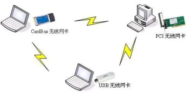
Ad-hoc networks are a type of point-to-point peer-to-peer mobile network that does not have the support of wired infrastructure, where all nodes in the network are composed of mobile hosts.
There are no wireless APs in the network, and communication is achieved freely through multiple wireless network cards. The basic structure is shown in the figure below:
To establish a peer-to-peer network, the following steps need to be completed:
1) First, install the wireless network card on your computer and configure the IP address and other network parameters for your wireless network card. Note that the IPs of the interconnecting hosts must be in the same subnet, as there is no gateway in a peer-to-peer network, so the gateway does not need to be filled in.
2) Set the operating mode of the wireless network card to Ad-hoc mode, and configure the same SSID, frequency band, encryption method, key, and connection rate for the network cards that need to be interconnected.
Note: All TP-LINK wireless network card products support this application mode.

2. Infrastructure Mode
The Infrastructure mode network is an application mode that integrates wired and wireless local area network architectures. In this mode, the wireless network card connects wirelessly with the wireless AP, and then establishes a connection with the wired network through the wireless AP.
In fact, Infrastructure mode networks can also be divided into two modes: one is the mode of connecting a wireless router with a wireless network card; the other is the mode of connecting a wireless AP with a wireless network card.
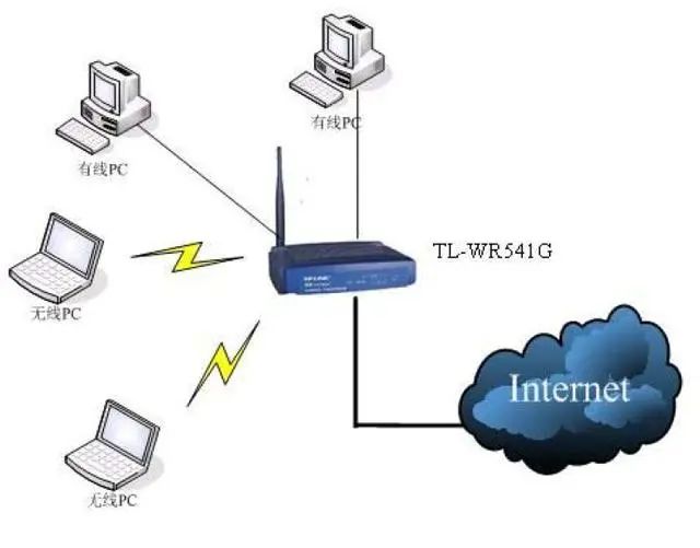
The “wireless router + wireless network card” mode is currently used by many households. In this mode, the wireless router acts as a wireless AP with routing functionality, used to connect wired and wireless networks.
For example, a company’s wireless router series not only integrates wireless AP functionality and routing functionality but also incorporates a wired four-port switch, allowing for mixed connections between wired and wireless networks, as shown in the figure below:
The other mode is the “wireless AP + wireless network card” mode. In this mode, how the wireless AP should be set up and how to connect with the wireless network card or wired network card mainly depends on the specific functions you want to achieve and the devices you plan to use.Because wireless APs have multiple working modes, the devices they can connect to and the connection methods may not be the same.
Below is the working modes and settings of a company’s wireless AP TL-WA501G (hereinafter referred to as 501G). This model supports five basic working modes: AP mode, AP client mode, repeater mode, Bridge (Point to Point) mode, and Bridge (Point to Multi-Point) mode.
1) AP Mode
AP (Access Point) mode is the basic working mode of our wireless AP, used to build a centralized control network centered on the wireless AP, where all communication is forwarded through the AP, similar to the function of a switch in a wired network. The connection method in this mode is roughly as shown in the figure below:
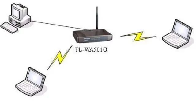
In this mode, the wireless AP can establish a wireless connection with the wireless network card and can also establish a wired connection with the wired network card through a network cable.
The 501G only has one LAN port, which is generally not used to connect directly to a computer but is used to connect to a wired network, directly connecting to the front-end router or switch. The settings for this mode are as follows:
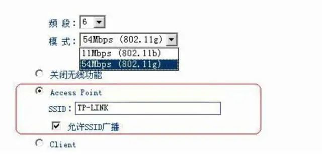
First, set the operating frequency range for the network, which should be selected from 1 to 13. When selecting, it is important to avoid using the same frequency band as other wireless networks in the surrounding environment. Then, select the working mode of the 501G. The 501G supports 802.11b with a bandwidth of 11Mbps and 802.11g with a bandwidth of 54Mbps (compatible with 802.11b mode).
Also, make sure to enable the wireless function by not selecting the option to ‘turn off wireless function’. Select the ‘Access Point’ option and set the SSID. Note that the SSID set on the wireless network card connecting wirelessly to our wireless AP must be the same as the SSID set on our wireless AP; otherwise, it will not be able to connect to the network.
2) AP Client Mode
In AP client mode, the network can connect either via wired or wireless, but the computers connected under the wireless AP can only connect via wired, not wirelessly. The connection method in AP client mode is roughly as shown in the figure below:
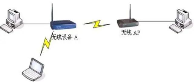
The wireless device A in the figure can be either a wireless router or a wireless AP. When the 501G needs to establish a wireless connection with our wireless router, the settings on the wireless AP are as follows:
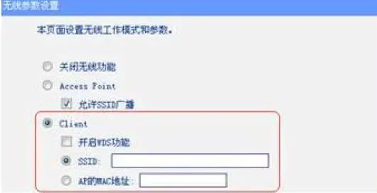
In client mode, there are two ways for the wireless AP to connect to the front-end wireless router: one is to set the same SSID as the wireless router to connect to it; the other is to fill in the MAC address of the LAN port of the wireless router in the ‘AP’s MAC address’ field to establish a connection.
● Enable WDS function – If WDS is enabled, 4-address packet format will be used for communication with the AP; otherwise, 3-address packet format will be used (mainly considering compatibility with the front-end wireless router).
● SSID – Specify the SSID to select the AP.
● AP’s MAC address – Specify the MAC address to connect to the AP.
Note: Currently, all of our company’s wireless routers support WDS, so whether WDS is enabled or not, it can connect.
When our wireless AP working in AP client mode connects to another wireless AP, the connecting wireless AP can be in AP mode or in repeater mode for the front-end signal. When the front-end AP is set to repeater mode, it does not have an SSID; therefore, to establish a connection, the wireless AP set to AP client must fill in the MAC address of the front-end AP in the ‘AP’s MAC address’ field.
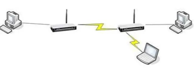
3) Bridge (Point to Point) Mode
In the wireless bridge mode, the wireless AP can connect wirelessly with the wireless network card and can also use the LAN port of the wireless AP to connect to a computer. When using this mode, generally both APs are set to bridge mode for direct connection, which is equivalent to connecting the LAN ports of both with a network cable. The specific connection is shown in the figure below:
The wireless AP set to bridge mode can enable its own AP function to connect to wireless workstations while also bridging by specifying the MAC address of the AP to be connected, as shown in the figure below:

For the two wireless APs to connect through bridge mode, set the MAC address of the opposite AP to connect with it.
It is important to note that both wireless APs must be set to the same operating frequency band; otherwise, they may not be able to connect. Of course, whether in the router or WA501G+, settings must consider the entire network’s gateway, DHCP server, etc.
4) Bridge (Point to Multi-Point) Mode
In wireless multi-point bridge mode, the wireless AP can work with up to four APs set to bridge mode to form a point-to-multipoint wireless network, and it can also enable AP functionality. The basic mode is shown in the figure below:
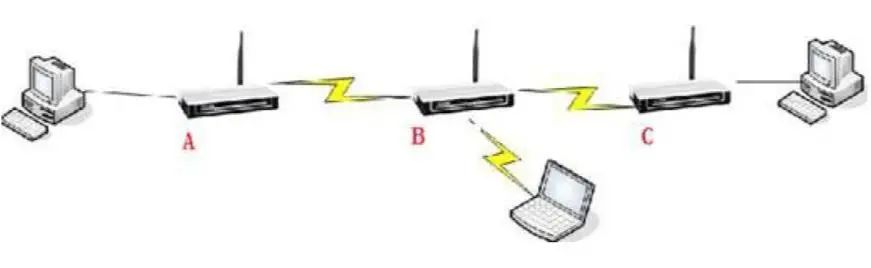
In the figure, there are three wireless APs, A, B, and C. Both A and C are set to bridge mode, while wireless AP B is set to multi-point bridge mode. Both A and C wireless APs must be set to point to B, meaning filling in the MAC address of wireless AP B. At the same time, wireless AP B must add the MAC addresses of both A and C wireless APs to establish a connection.
The wireless AP set to multi-point bridge mode has multiple fields for filling in MAC addresses, and if fewer than two entries are filled, an error will occur when saving. This means that when the wireless AP is set to multi-point bridge mode, it must connect with at least two other wireless APs. Our 501G can connect with up to four wireless APs simultaneously in multi-point bridge mode. If the AP functionality is enabled, it can also connect to wireless workstations. The settings interface is shown in the figure below:

5) Repeater Mode
In repeater mode, the wireless AP serves to amplify and retransmit the signal, so it can connect with a wireless AP set to AP mode and relay its signal. The repeater mode wireless AP can also connect with another wireless AP set to repeater mode. As shown in the figure below:
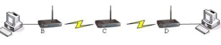
The repeater mode wireless AP is mainly used to expand the coverage of the wireless network. In the figure, assume that the computers under B and D need to communicate with each other, but B’s signal cannot reach D; therefore, we can add a wireless AP in between to relay B’s signal, thus enabling communication between B and D.
We can set B to AP mode, set C to relay B, and then set D to relay C, thereby enabling communication between B and D. To set C to relay B, simply fill in B’s MAC address in C’s ‘AP’s MAC address’ field. As shown in the figure below:

● Universal mode refers to using a non-WDS mode to communicate with the AP, which has broader compatibility.
Currently, wireless networks have become the new favorite of modern office environments. However, a single AP has limited coverage; therefore, some larger companies often install two or more wireless APs to expand the coverage area of the wireless network. However, they encounter the issue that when mobile users switch between different wireless APs, they must search for the wireless network and reconnect each time, which is very cumbersome.
In this case, we introduce a new concept called wireless roaming.
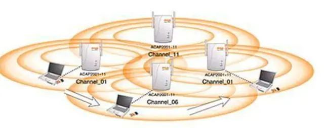
Wireless signals are continuously attenuated during transmission, causing the communication range of the AP to be limited to a certain range, usually referred to as a microcell. When multiple wireless APs exist in the network environment and their microcells overlap to some extent, wireless users can move within the entire wireless signal coverage area, and the wireless network card can automatically discover the nearby wireless AP with the strongest signal strength and communicate through this AP to maintain uninterrupted network connectivity, which is called wireless roaming.
In practical applications, sometimes there is only one exit for wireless, as shown in the application below. The following figure shows a seamless roaming network composed of four wireless APs, where the four wireless APs are connected to the wired network via network cables, forming a wireless network based on the wired network, allowing all terminals to access the network through the nearest wireless AP.
To achieve seamless roaming, we must first assign IP addresses to each wireless AP and ensure that all wireless APs’ IP addresses are in the same subnet. Each wireless AP should be set to AP mode, and the SSID must be the same.
If encryption is to be set, then the encryption method and key of the wireless AP must also be the same. It is best to leave the DHCP function only in the upstream wireless router and disable the DHCP function of the wireless AP; otherwise, it will lead to confusion in IP address allocation.
In the figure, we can see that to achieve roaming, the coverage areas of wireless APs must overlap, and if the overlapping wireless APs use overlapping channels, their signals will interfere with each other during transmission, thereby reducing network performance and efficiency. Therefore, the channels used by the coverage areas of overlapping APs must follow certain regulations, and overlapping APs cannot use the same channel.
The 802.11b protocol operates on channels in the 2.4000GHz~2.4835GHz range, with a total of 11 overlapping channels, of which only three channels do not overlap: channel 1, 6, and 11, as shown in the figure below:
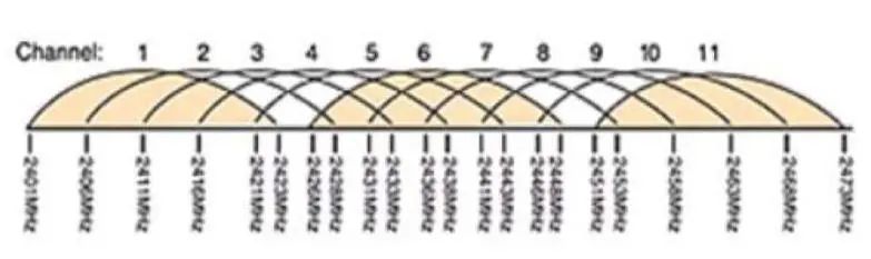
Therefore, using these three channels is the most suitable for seamless roaming. If we configure simple wireless roaming, we only need the roaming area to be the overlapping area of each wireless AP, and the SSID numbers and encryption methods of each AP must be consistent.
– END –
///
Professional • Strength • Integrity • Value

WeChat ID:sannet-edu
Official Website:www.sannet.net
Consultation Hotline:0512-82289966
Address: Room 433, Heji Plaza, No. 666, Ganjiang East Road, Suzhou