The PLC Workflow: Only Three Steps, Yet 90% of Engineers Are Left Behind!

The PLC Workflow: Only Three Steps, Yet 90% of Engineers Are Left Behind!

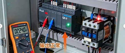
Introduction The PLC is known as the “nerve center” of modern factories; however, its workflow consists of only three steps: input sampling, program execution, and output refreshing. Yet it is the subtle differences in these three steps that create a gap between novices and experienced engineers, causing 90% of engineers to hesitate. 1. Input Sampling: … Read more

Four Essential Steps for PLC Debugging: A Practical Guide for Electrical Engineers from Power-On to Operation

Four Essential Steps for PLC Debugging: A Practical Guide for Electrical Engineers from Power-On to Operation

PLC debugging is the “last mile” of electrical project implementation—no matter how perfectly the program is written or how standard the wiring is, if there are issues during the debugging phase, the equipment will not operate normally. Many engineers, when first encountering debugging, often fall into the trap of “power on with no response → … Read more

The ‘Left Hand and Right Hand’ of PLC: Digital and Analog Signals, Don’t Get Confused

The 'Left Hand and Right Hand' of PLC: Digital and Analog Signals, Don't Get Confused

In the world of PLCs, all signals can be divided into two main categories: Digital and Analog. They are the “left hand and right hand” of PLCs in perceiving and controlling the external world, and understanding the difference between the two is crucial. 1. Digital: The Black-and-White ‘Switch’ Signal Core Characteristics: There are only two … Read more

Detailed Analysis of the Main Differences Between DCS and PLC

Detailed Analysis of the Main Differences Between DCS and PLC

Choosing between a Programmable Logic Controller (PLC) and a Distributed Control System (DCS) requires a specific analysis based on the situation, as different applications have varying requirements for control systems. When communicating with clients, we can approach the discussion from the following aspects! PLC and DCSPLC 1. Development from switch control to sequential control, transport … Read more

Principles of PLC Control Cabinet Design: Wiring Layout, Connection Diagrams, and Schematics

Principles of PLC Control Cabinet Design: Wiring Layout, Connection Diagrams, and Schematics

1. Wiring according to the diagram is the highest principle and cannot be overstated.First, before wiring, one must carefully read the drawings and fully understand the designer’s intentions, rather than relying on personal so-called rich experience. If any unclear or contradictory points are found, one should immediately contact the designer for confirmation before proceeding with … Read more

Performance Analysis of Siemens S7-200 SMART PLC

Performance Analysis of Siemens S7-200 SMART PLC

1. Core Functions and Technical Features High Performance and Flexibility Signal Board Design: Supports extended communication ports (RS232/RS485), digital and analog channels, without occupying additional control cabinet space, reducing costs. Processor and Calculation Speed: Equipped with Siemens’ dedicated high-speed processor, with a basic instruction execution time of 0.15μs, leading in performance among similar small PLCs, … Read more

Directly Collecting PLC Data with MQTT: A Game Changer!

Directly Collecting PLC Data with MQTT: A Game Changer!

In the fields of automation and Industrial Internet of Things (IIoT), Programmable Logic Controllers (PLCs) have played an indispensable role. With the development of network technology, real-time collection and management of PLC data has become a crucial demand for smart factories. MQTT, as a lightweight communication protocol, demonstrates its unique advantages in PLC data collection. … Read more

Comprehensive Guide to PLC Input and Output Circuit Wiring: Essential Knowledge for Beginners!

Comprehensive Guide to PLC Input and Output Circuit Wiring: Essential Knowledge for Beginners!

1. Input Circuit Wiring The input circuit is the port through which the PLC receives signals (for analog signals, it is generally a DC current of 0-40MA or a DC voltage signal of 0-10V). Input wiring refers to the external input devices (any passive contacts and NPN transistors with open collector) that connect to the … Read more