Source | Renesas Embedded Encyclopedia
With the development of embedded systems, the demand for code upgrade functionality in products is increasing. Code upgrades can achieve goals such as supporting new features and fixing bugs.
The essence of a code upgrade is the process of erasing and writing to the on-chip flash memory (mainly code flash). Since it is necessary to operate on the flash content while the code is running, there are some special considerations to keep in mind.
For example, if an exception occurs during the transmission process, causing the code upgrade to fail, can the device start normally from that state and recover to the state before the last upgrade? Additionally, if the new code burned into the chip has vulnerabilities, or if the transmission path is compromised, can the device detect this anomaly and refuse to run that code?
Furthermore, since code upgrades are closely related to the flash structure of the chip, considerations such as whether the interrupt vector table needs to be relocated during this process must also be taken into account.
There are various ways to implement code upgrades, and system architectures vary widely. How to find a suitable upgrade method among many options requires users to evaluate based on the needs of the application scenario.
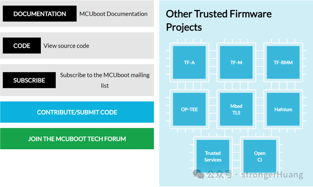
Here, we introduce a secure boot code framework aimed at 32-bit microprocessors—MCUboot.
What are the specific features of MCUboot? They are mainly as follows:
-
Fully open-source and continuously updated
-
Supports various upgrade modes: overwrite, swap, direct XIP (Execute In Place), and loading into RAM for execution
-
Performs secure verification of new firmware, with the level of security verification selectable based on actual needs
-
Can recover from upgrade exceptions
Where can you find resources related to MCUboot? You can visit the MCUboot official website, where the source code is hosted on GitHub.
Official website:
http://www.trustedfirmware.org/
 Open-source address:
https://github.com/mcu-tools/mcuboot

Since MCUboot is a system framework, it defines the partitioning of the chip’s flash, dividing the entire chip’s storage space into Bootloader, Primary Slot, and Secondary Slot. In a sense, the Primary Slot and Secondary Slot back each other up, and their roles vary under different upgrade modes, which we will detail later.
For a 32-bit microcontroller, customers can port MCUboot to adapt it to their current products. The Renesas MCU development toolRenesas FSP integrates this functionality, allowing users to configure MCUboot-related information with just a few clicks, similar to adding a regular peripheral driver.
Flexible Software Package FSP:
https://www.renesas.cn/cn/zh/software-tool/flexible-software-package-fsp
Using FSP’s support for MCUboot as an example, we will introduce the relevant features of MCUboot.
First, we will introduce the four upgrade modes supported by MCUboot: Overwrite, Swap, Direct XIP, and loading into RAM for execution. Since FSP does not support the fourth mode—loading into RAM for execution—we will focus on the first three.
Overwrite Mode
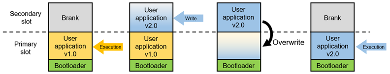
MCUboot Overwrite Mode Diagram
In Overwrite mode, the starting point is that the chip has the Bootloader and User Application v1.0 (initial version) burned in. Upon power-up, the Bootloader checks the contents of the Secondary Slot and Primary Slot. Since the Secondary Slot is empty at this time, the Bootloader checks the integrity of the Image (image file) in the Primary Slot. Once confirmed to be valid, it jumps to execute User Application v1.0 in the Primary Slot (the PC pointer runs in the Primary Slot, indicated by the yellow Execution arrow).
During the execution of the code, if an upgrade request is received, it will accept the new Image and burn it into the Secondary Slot. The method of receiving the new Image depends entirely on the implementation of the user application, which can be via USB, Ethernet, Modbus, etc. After burning is complete, a soft reset command is executed, causing the chip to return to the reset vector table to start executing the Bootloader. At this point, the Bootloader finds that there is new code in the Secondary Slot, and if its version is v2.0, which is higher than v1.0 in the Primary Slot, it will copy the contents of the Secondary Slot to the Primary Slot and then erase the Secondary Slot.
Comparing the initial and final states of the entire process, we find that the code running on the chip has been upgraded from the lower version v1.0 to the higher version v2.0.
From the process of Overwrite mode, some characteristics can be observed:
-
Due to the relatively simple code design, the code size introduced by the Bootloader is small, allowing more space for application use.
-
Overwrite does not support code rollback. That is, if a new Image is burned into the chip, the old Image will no longer exist after the upgrade is complete.
-
The code is only backed up in the Secondary Slot and not executed; it must be copied to the Primary Slot for execution, so the address space for compiling/linking the Application Image used for the upgrade is always the Primary Slot address space.
-
Since the entire process requires two erases (Primary Slot and Secondary Slot) and one write (Primary Slot) to the flash, the entire Boot process depends on the characteristics of the flash, mainly the erase/write speed.
For Renesas RA series products, if the MCUboot module is added to the stack, the upgrade mode modification interface is as follows.
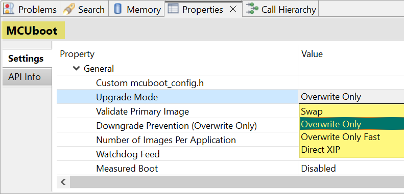
FSP MCUboot Upgrade Mode Options
Note: Overwrite Only and Overwrite Only Fast are quite similar; the only difference is that the latter only copies the sectors (which can be understood as Flash Blocks) used from the Secondary Slot to the Primary Slot, leaving unused portions un-copied.
Swap Mode
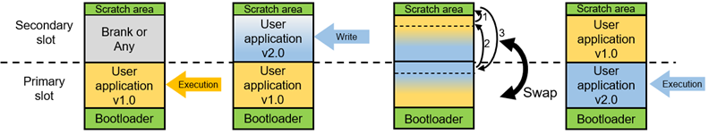
MCUboot Swap Upgrade Mode Diagram
From the system block diagram perspective, compared to Overwrite mode, Swap mode has an additional Scratch area for storing intermediate content exchanged between the two slots.
For simplification, in Swap mode, we still assume the starting point is that the chip has the Bootloader and User Application v1.0 (located in the Primary Slot). During code execution, if an upgrade command is received, it accepts the new Image (User Application v2.0) from external sources and burns it into the Secondary Slot. After completion, a soft reset is executed, and the chip returns to run the Bootloader. At this point, the Bootloader determines that there is a higher version v2.0 code in the Secondary Slot, checks its integrity, and once confirmed valid, swaps the contents of the Primary Slot and Secondary Slot in blocks.
After the swap is complete, the Primary Slot retains the high version v2.0 Image, while the Secondary Slot holds the low version v1.0 Image, and the code continues to execute from the Primary Slot.
In the initial state of Swap mode, the Primary Slot runs the low version v1.0 Image, while in the final state after the upgrade, the Primary Slot runs the high version v2.0 Image, thus completing an upgrade.
From the process of Swap mode, some characteristics can be observed:
-
Supports code rollback/downgrade. Since the low version v1.0 Image is still stored in the chip after the upgrade is complete, if a bug is found in the high version v2.0 that needs fixing, the upgrade program can be re-executed to revert the code back to v1.0.
-
Due to the more complex functionality of the code, the code size introduced by the Bootloader is larger. Under the same conditions, the code for Swap mode is the largest. Additionally, since a Scratch area is reserved for code swapping, less space is available for the application.
-
During the entire upgrade process, both the Primary Slot and Secondary Slot undergo one erase and one write each, resulting in a longer Boot time.
-
Since the flash is specifically partitioned with a Scratch area for code swapping between the two Slots, multiple erase/write operations will occur in that area during the upgrade process. The specific number of erase operations depends on the size of the Scratch area and the Slot size, with a simple calculation being the Primary Slot size divided by the Scratch area size, which gives the number of erase operations for the Scratch area. The number of write operations equals the number of erase operations.
———— END ————
Principles and Methods for Implementing OLED Display via I²C with MCU
Methods for Automatic Baud Rate Detection in MCU Serial Ports

How to Form a Development Team for Embedded Projects?