
Wireless Remote Control and Adjustment Network Using S7-300 PLC
When the distance between multiple control points is very far, and they are remote and scattered, such as water source wells, valves, and water level monitoring in urban water supply and hydraulic departments, these devices are spread over dozens or even hundreds of square kilometers. To control and monitor these scattered devices or sensors, using a bus or centralized control method is no longer feasible, so people often use wireless control to solve this problem. Below is a method for constructing a wireless remote control and adjustment system using S7-300 PLC, as shown in Figure 1.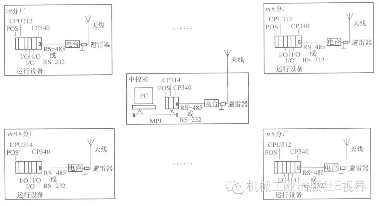
Figure 1 Wireless Remote Control and Adjustment System Using S7-300 PLC
The main station in the central control room consists of the S7-300 PLC‘s CP314 and CP340 communication modules, with the CP340 communication module’s RS-485 (or RS-232) port connected to the radio’s RS-485 (or RS-232) port. A lightning arrester is connected between the radio and the antenna to prevent equipment damage from lightning strikes.
The peripheral substation consists of CPU312FM, several I/O modules, and CP340 communication module. The number of I/O modules is configured based on the number of field devices and signal types. The CP340 communication module’s RS-485 (or RS-232) port is connected to the radio’s RS-485 (or RS-232) port, with a lightning arrester connected between the radio and antenna to prevent equipment damage from lightning strikes. The connection between the communication radio and CP340 is shown in Figure 2.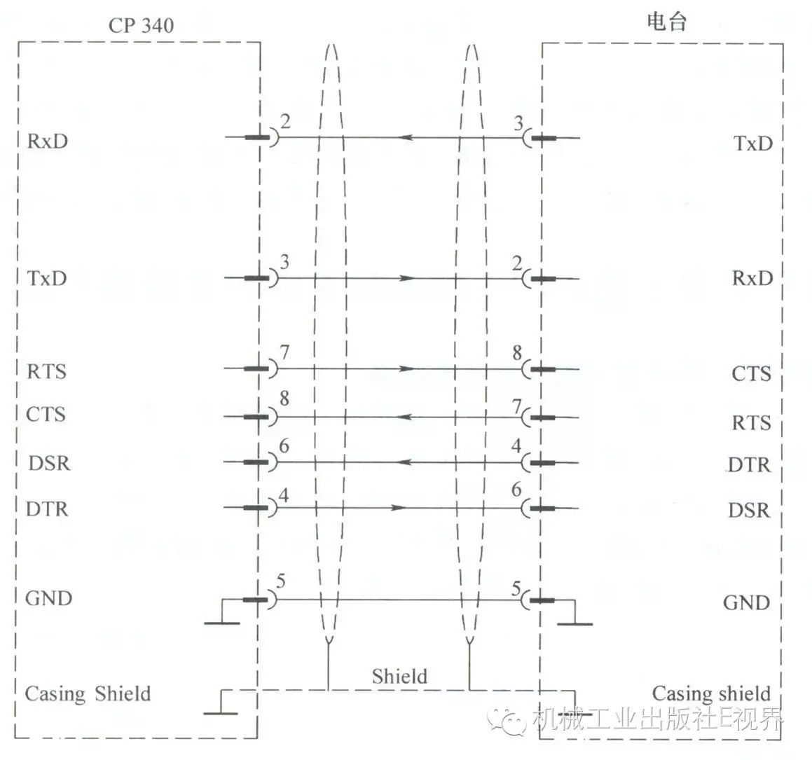
Figure 2 Connection between Communication Radio and CP340
The main station in the control room is required to sequentially query the data from each substation. The data sent by the control room’s PLC includes the address of the called substation and the control instructions for that station. When the substation receives the instructions with that address, it sends back the inspection data to the control room and switches devices and adjusts the process target set values according to the control commands. The data address sent by the control room’s PLC is incremented by 1 to cycle to the next station, thus achieving inspection and control of each wireless substation from the control room.
Wireless Remote Control and Adjustment Network Using S7-200 PLC
If using S7-200 PLC for wireless communication, a CPU224 or CPU226 with dual communication ports can be used. The pin layout and meaning of communication ports 0 and 1 are shown in Figure 3.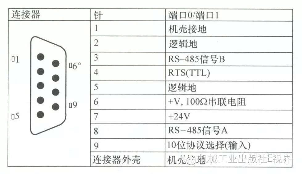
Figure 3 Pin Layout and Meaning of Communication Ports 0 and 1
Connect the data transmission radio to communication port 0, set communication port 0 to free port mode, which is controlled by program programming. If the radio communication port is RS-485, it can be connected directly; if the radio communication port is RS-232, then an RS-232/PPI adapter cable is needed to convert RS-232 to RS-485 wiring method. At the same time, set the DIP switch DIP5 to 0, and use DIP1, 2, 3 to select the communication rate.
PLC activates free port mode when in RUN state, and when PLC is in STOP state, the free port reverts to PPI protocol (point-to-point interface, can connect to programming PC).
Special memory byte SMB30 defines communication port 0, special memory byte SMB130 defines communication port 1. The free port generates interrupt event 8 after receiving data, and puts the data into SMB2. SMB3 is used for parity check of data received by the free port; if there is a parity error, then SMB3.0=1, which can be programmed to check this bit SM3.0 for data acceptance. When communication port 0 is idle, SM4.5=1. SM4.0=1 indicates communication interrupt overflow, meaning the processing speed of the interrupt program is lower than the frequency of the interrupts. The meaning of SMB30 is shown in Table 1; for example, if SMB30=9 (binary 1001), it indicates that communication port 0 is defined as free port protocol, with a communication rate of 9600 baud rate, 8 data bits, no parity.
Table 1 Meaning of SMB30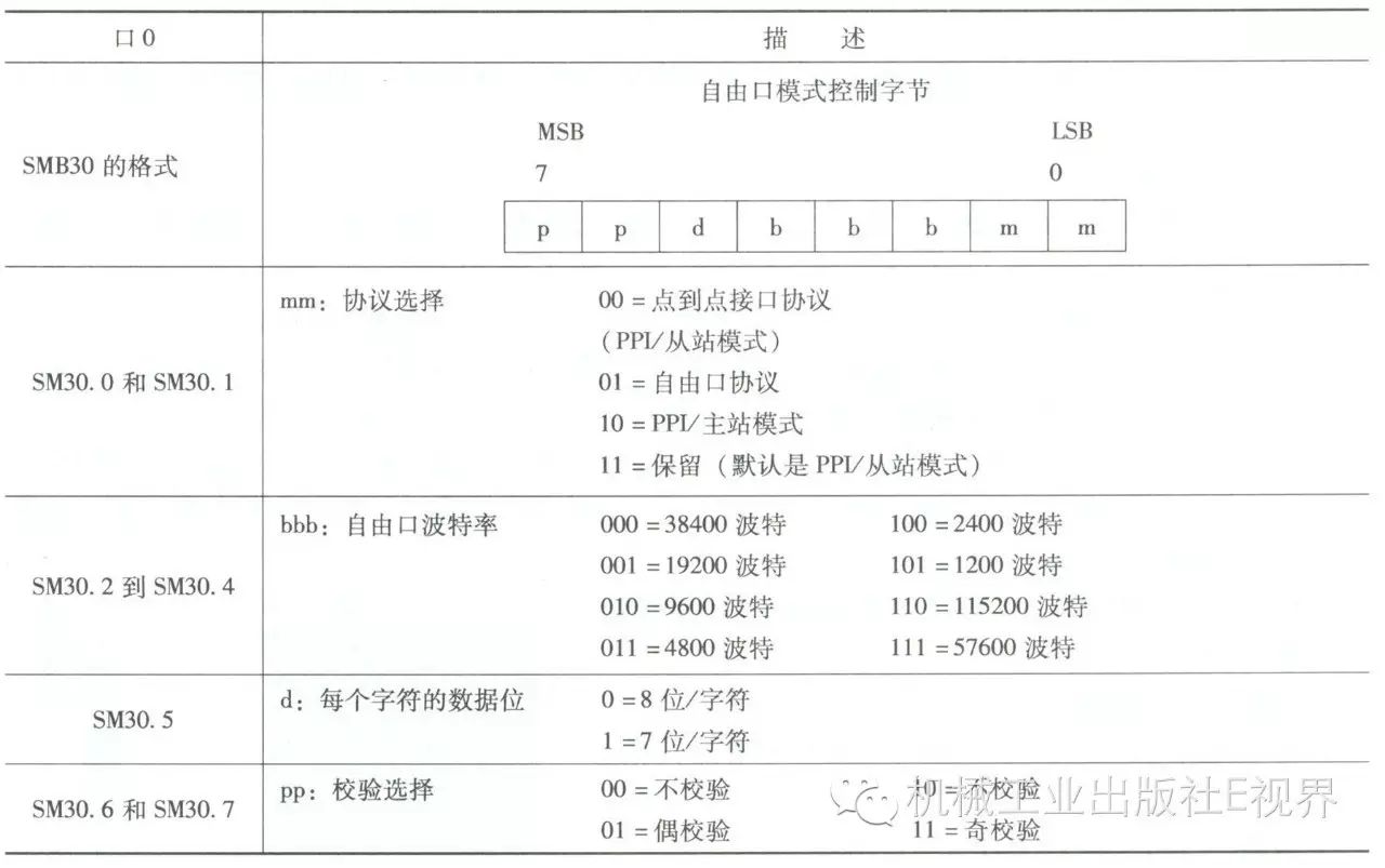
SM34 generates a timed interrupt 0, with a timing reference of 1ms, a timing range of 1~255ms, and when the timing time is reached, it generates a timer 0 interrupt event 10.
After completing the data transmission, a free port transmission data completion interrupt event 9 is generated.
The transmission instruction XMT specifies the communication port 0 and the storage address of the number of bytes to be transmitted, such as VB200 specifies the number of transmissions (for example, 13 units), starting from VB201 to transmit.
Wireless Data Monitoring Network Using MD720-3 Module
Solution 1:Multiple remote stations, each including S7-224XP, where the S7-224XP‘s PORT1 connects to MD720-3 module via PC/PPI cable; a dedicated antenna is installed on the MD720-3 module, which has a SIM card installed, and the SIM card has GPRS functionality enabled; the central station consists of WinCC configuration monitoring software, SINAUT MICRO SC routing ( OPC) software, and a fixed IP address ADSL and PC. The remote station connects to the central station with a fixed IP address through GPRS service of the GSM network.
S7-200 and MD720-3 module forms GPRS wireless data monitoring as shown in Figure 4.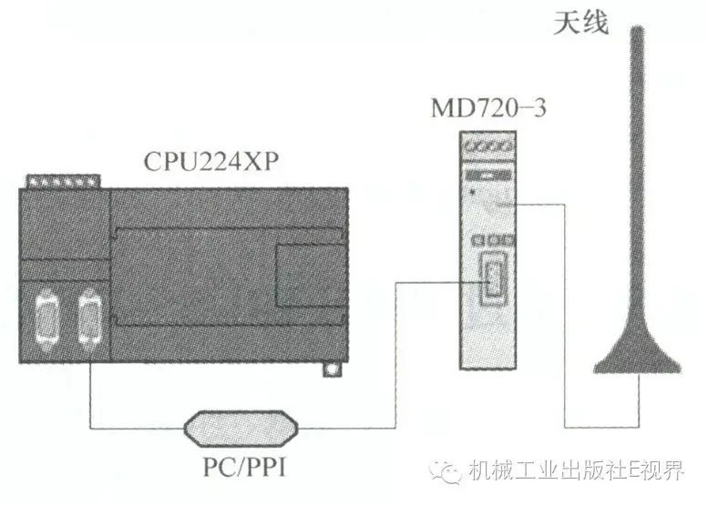
Figure 4 S7-200 and MD720-3 module forms GPRS wireless data monitoring
Remote station hardware structure:
S7-224: 6ES7 214-2BD23-0XB8 (with two communication ports for easy debugging, plus necessary I/O modules);
PC/PPI cable: 6ES7901-3CB30-0XA0 (one end connects to PLC‘s PORT1, the other end connects to MD720-3 module);
MD720-3 module: 6NH9720-3AA00;
ANT794-4MR antenna: 6NH9860-1AA00;
Central station structure:
Telephone line;
ADSL internet MODEM (one end connects to the telephone, the other connects to the computer RJ45 port, apply for a fixed IP address from the telecommunications department);
PC (with RJ45 internet port);
SINAUT Micro SC routing software (with 8, 64, 128, 256 terminal authorizations): 6NH9910-0AA10, 0AAX;
WinCC 6.1 configuration software (with 128, 256 point authorizations): 6AV6381-1BM06-0DV0.
Solution 2:Multiple remote stations including S7-314, CP340 module, with the CP340 module’s RS-232 port connected to the MD720-3 module ( + dedicated antenna), with the CP340 module’s RS-232 port directly connected to the MD720-3 module (1-1, 2-2…); the MD720-3 module has a SIM card installed, and the SIM card has GPRS functionality enabled; the central station consists of WinCC configuration software, SINAUT MICRO SC routing software, with a fixed IP address ADSL, and PC, the remote station connects to the central station with a fixed IP address through GPRS service.
S7-300 and MD720-3 module forms GPRS wireless data monitoring as shown in Figure 5.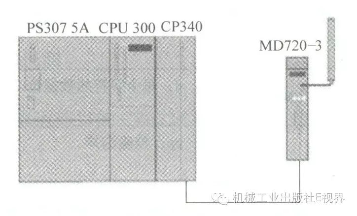
Figure 5 S7-300 and MD720-3 module forms GPRS wireless data monitoring
Remote station hardware structure:
S7-300: 6ES7 314-1AE01-0AB0 (add other necessary I/O modules);
CP340: 6ES7 340-1AH00-0AE0;
MD720-3 module: 6NH9720-3AA00;
ANT794-4MR antenna: 6NH9860-1AA00.
Central station structure:
Telephone line;
ADSL internet MODEM (one end connects to the telephone, the other connects to the computer RJ45 port, apply for a fixed IP address from the telecommunications department);
PC (with a RJ45 internet port);
OPC routing software SINAUT Micro SC (with 8, 64, 128, 256 terminal authorizations): 6NH9910-0AA10-0AA8;
WinCC 6.1 configuration software (with 128, 256 point authorizations): 6AV6381-1BM06-0DV0.
Web navigator network publishing software, remote clients can view data through the central station with a fixed IP address.
Related Reading
PLC Programming Principles, Languages, Methods, Common Instructions and Examples
Common Electrical Circuit Symbols
Common Electrical Control Circuits