In the previous article (Implementing a PCIe Device in Qemu: Supporting SGL DMA), we added a Bit Flip functionality (bitwise negation) to the PCIe device simulated in Qemu. In this functionality, we implemented support for Scatter-Gather List DMA (SGL DMA), allowing the use of non-contiguous physical memory as a DMA buffer. This article will introduce how to use this SGL DMA in a WDF driver and also test the Bit Flip functionality added to this PCIe device.
Typically, the physical memory corresponding to the allocated memory is not necessarily contiguous, unless using system-provided functions to allocate contiguous physical memory. Even then, it may not be possible to allocate contiguous physical memory, especially if the system has been running for a long time and memory fragmentation is severe. Therefore, hardware support for non-contiguous physical memory SGL DMA is very friendly for operating systems and drivers, as these system software will not face many limitations when handling DMA.
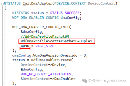
To support SGL DMA in a WDF driver, you first need to specify a DMA Profile with ScatterGather when creating the DMA Enabler. We choose ScatterGather64Duplex (64-bit physical address, supporting simultaneous DMA read and write). Since the hardware supports SGL DMA, the amount of data transferred in a single DMA operation can be greatly increased; here we set it to 4096 pages, which is 16M.
 In the previous article (Windows PCI Device Driver Development Guide: How to Use DMA), we introduced how to create a DMA Adapter through the DMA Enabler, then allocate a DMA address-contiguous “Common” Buffer through the DMA Adapter, and finally actively configure the DMA address to trigger the device’s DMA transfer. This approach only utilizes the DMA Adapter’s function to allocate DMA Buffers. This article will introduce another method, which allows us to utilize the WDF driver framework’s capability to create SCATTER_GATHER_LIST and configure DMA through WDF framework callback functions. First, we need to introduce several important WDF API functions:WdfDmaTransactionCreate
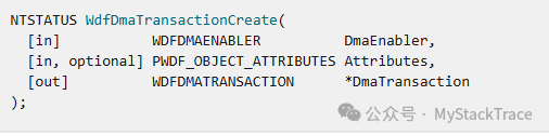 This function creates a WDF DMA transaction object.
WdfDmaTransactionInitialize
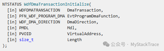 This function initializes an already created DMA transaction object based on a virtual address and the corresponding MDL. This function also requires the driver to provide a callback function EvtWdfProgramDma to configure the hardware DMA operation. The prototype of this callback function is as follows, where you can see that the parameters include the corresponding DMA transaction and the SCATTER_GATHER_LIST created by the WDF framework based on the MDL. We create the SGL structure supported by the device based on this structure, then configure it to the device and trigger the device’s DMA transfer.
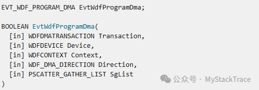
WdfDmaTransactionExecute
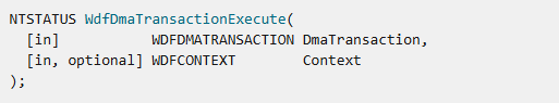
This function executes the DMA transaction. It does not directly execute the DMA transfer; instead, it first creates and initializes the SCATTER_GATHER_LIST based on the MDL bound to this DMA transaction, then calls the driver-provided EvtWdfProgramDma callback function to configure the device’s DMA and trigger the device’s DMA transfer.
WdfDmaTransactionDmaCompleted
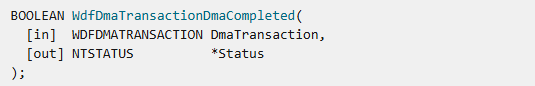
This function can be used to notify the WDF framework that a DMA transfer has been completed. If a single DMA transaction is divided into multiple DMA transfers, this function will return different status values based on whether all these DMA transfers have been completed. If there are still DMA transfers to be done, the WDF framework will call the EvtWdfProgramDma callback function again.
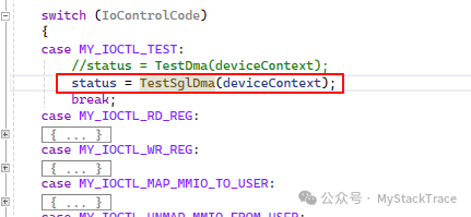
After understanding these functions, we can write the program. Similar to the previous test of vector addition, we will write a test function TestSglDma in the driver and use an application to call this test function through Test IOCTL.
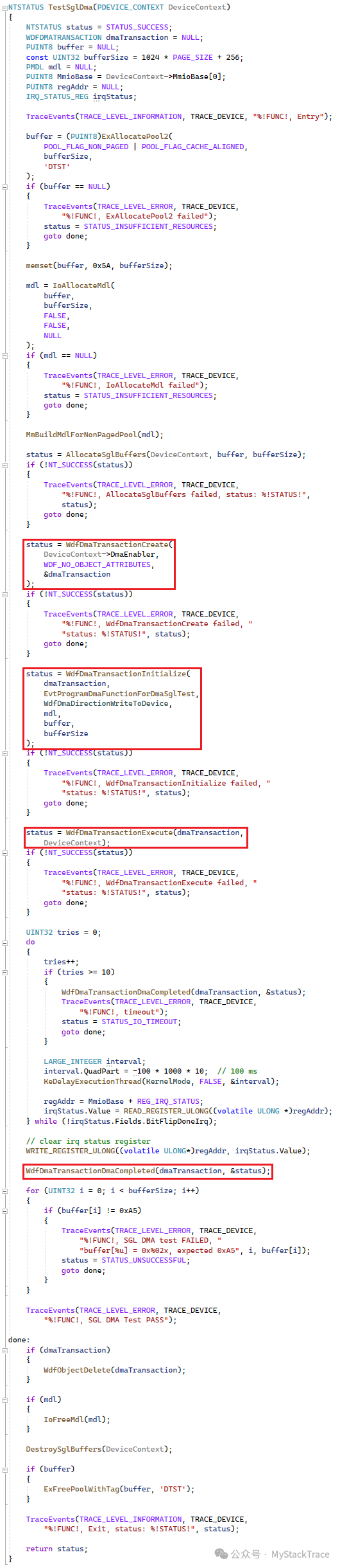
The implementation of the test function TestSglDma is as follows. You can see that the main line is to call the several WDF functions introduced above. In addition, we also need to allocate a large DMA buffer (1024 pages plus 256 bytes) and create the corresponding MDL. This way, we have a DMA buffer for data transfer, but we also need to store the SGL’s DMA buffer. The device actually needs to know the address of the SGL, as it can find all the physical addresses or DMA addresses used for data transfer through the SGL. Therefore, after allocating the DMA data buffer, we also need to allocate the SGL’s DMA buffer based on the size of the data buffer, which is what the function AllocateSglBuffers does.
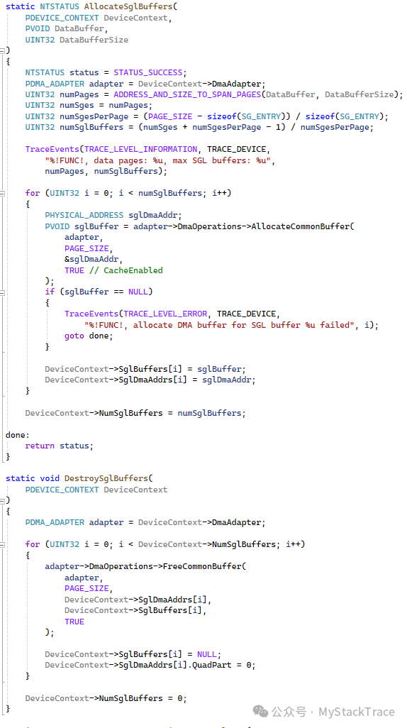
Next, let’s look at the implementation of the functions for allocating and releasing SGL buffers. It actually calculates the number of SG Entries needed based on the number of pages occupied by the data DMA buffer, then divides the number of SG Entries by the number of SG Entries that can fit in one page to get the total number of pages needed to store all these SG Entries. Finally, it uses the DMA Adapter’s AllocateCommonBuffer to allocate these SGL pages one by one. The operation to release these SGL buffers is relatively simple, so we won’t elaborate on it here.
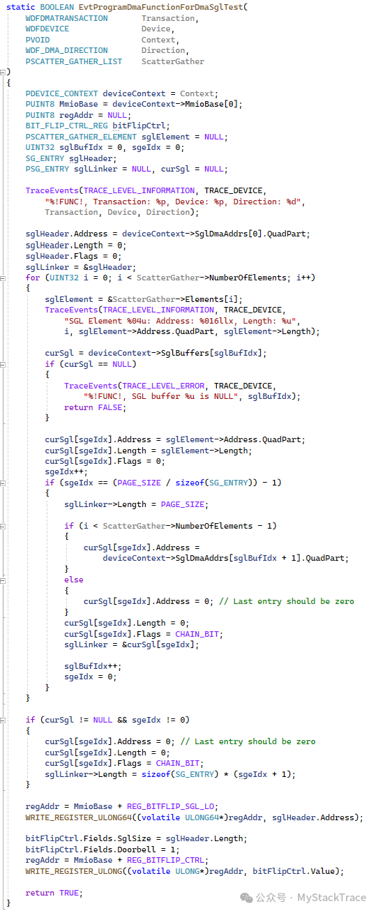
Now, returning to the function TestSglDma, after calling WdfDmaTransactionExecute, the EvtWdfProgramDma callback function will be called, and its specific implementation is as follows. First, based on the SCATTER_GATHER_LIST structure created by the WDF framework, we create the SGL structure defined by our PCIe device. Each SGL has a maximum size of one page. If multiple SGLs are needed, the last SG Entry of the previous SGL points to the starting physical address of the next SGL and indicates the size of the next SGL. After the SGL linked list is created, we need to configure the starting physical address of the 0th SGL in the PCIe device’s REG_BITFLIP_SGL_LO/HI registers, set its size in the REG_BITFLIP_CTRL register, and write 1 to the doorbell bit of the REG_BITFLIP_CTRL register to trigger the PCIe device to start executing the DMA operation.
After reviewing the EvtWdfProgramDma callback function, let’s return to the function TestSglDma. After the successful execution of the WdfDmaTransactionExecute, we will poll the BitFlipDoneIrq bit of the interrupt status register. If it is set to 1, it indicates that the PCIe device has completed this Bit Flip operation, and all bits in the provided data DMA buffer have been flipped. Finally, we check whether all bits have been flipped to verify whether the PCIe device’s operations are correct.
That concludes the situation of all the test code. Now let’s look at the test results. We still trigger the driver to execute the test function through the TestApp calling the MY_IOCTL_TEST IOCTL. Initially, the DMA buffer allocated by the driver was surprisingly contiguous in physical addresses, so we could not measure the effect of the SGL linked list. Later, by increasing memory pressure on the Qemu virtual machine, the driver finally allocated non-contiguous physical memory, achieving the purpose of verifying the SGL linked list.
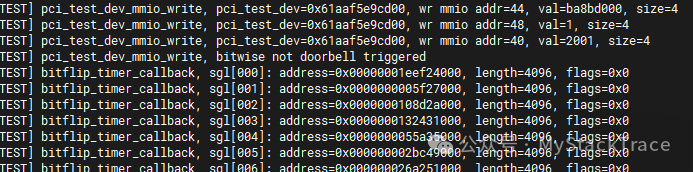
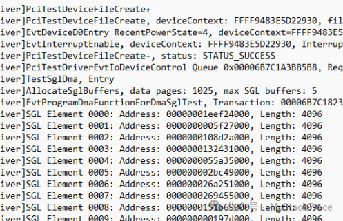
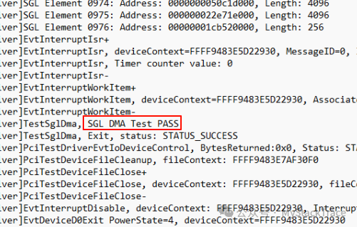
Below are the logs printed during the driver testing process. We can see that the physical memory allocated is indeed quite fragmented, with nearly a thousand pages. Finally, the verification of the device’s execution results is also correct, and the test passed, indicating that our implementation in Qemu is functioning correctly.
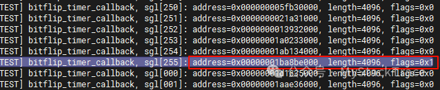
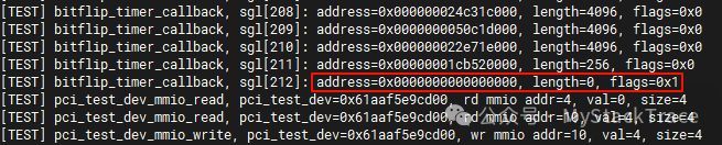
Below are the logs output by Qemu during the testing process. We can see that the flags of the last (255th) SG Entry of the SGL are all 1 (CHAIN_BIT set to 1), indicating that it points to the starting physical address of the next SGL. The last SG Entry of the last SGL has both address and length set to 0, indicating the end of the SGL linked list.