In this article (Implementing a PCIe Device in Qemu: Adding DMA Functionality), we added a vector addition feature to the PCIe device simulated with Qemu. This PCIe device uses DMA read operations to transfer the contents of two operand vectors provided by the driver into an internal buffer of the PCIe device, computes the sum vector in the internal buffer, and finally transfers the sum vector from the internal buffer of the PCIe device back to the memory allocated for the sum vector by the driver using DMA write operations. Later, in this article (Windows PCI Device Driver Development Guide: How to Use DMA), we modified the driver to enable it to perform DMA operations and wrote a simple function in the driver to test the vector addition functionality. In this article, we will introduce how to access DMA from user mode. Previously, we implemented how to access the MMIO registers of the PCIe device from user mode and how to obtain interrupt events from user mode. These all require the driver to provide corresponding interfaces (IOCTL) for cooperation, and accessing DMA from user mode is similar, also requiring support from the driver.We will demonstrate how to access the DMA of the PCIe device from a user-mode application by testing the vector addition functionality of this PCIe device. To use DMA functionality in user mode, there are two prerequisites: first, the user mode must be able to access the registers of the PCIe device to configure the DMA address and trigger the device to perform vector addition operations, which we have already implemented (refer to Mapping MMIO to User Mode Address Space), and second, the user mode must be able to obtain the DMA address of the memory allocated in user mode. Currently, user mode does not have the capability to obtain DMA addresses, but based on the previous articles, you might have thought of using the driver to provide corresponding IOCTL requests to achieve this, and that is exactly what I plan to do.We can implement two IOCTLs in the driver of this PCIe device: one to map user-mode memory to kernel mode and obtain the DMA address, and the other to unmap the user-mode memory from the previously obtained DMA address and release resources. We will call these two IOCTL requests Map DMA buffer and Unmap DMA buffer.Map DMA buffer requires the application to provide the user-mode address and mapping length, so we need an input data structure (MAP_DMA_INFO) to store this information. After the driver processes the mapping, it obtains the DMA address and returns it to the application through the output buffer of the IOCTL. During this process, the driver will record which DMA mappings the application has performed in the device context for later use when unmapping.Unmap DMA buffer requires the application to provide the obtained DMA address, and the driver will query its previously maintained DMA mappings based on this DMA address and unmap it. Next, let’s look at the implementation of these two IOCTL requests in the driver. Similar to the previously implemented IOCTL requests, we need to add two cases in the switch…case of the function EvtIoDeviceControl in the IO queue, which handles the IoControlCode. After checking the parameters, the specific logic for Map DMA buffer and Unmap DMA buffer is handled by the functions MapDmaBuffer and UnmapDmaBuffer.
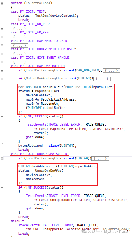 Since the application may need to perform multiple DMA mappings, we need to maintain a custom DMA_MAPPING structure array DmaMappingSlots in the device context structure DEVICE_CONTEXT to record the DMA mappings performed by user mode. When the application needs to release a DMA mapping, the driver can find the corresponding mapping information from this array.
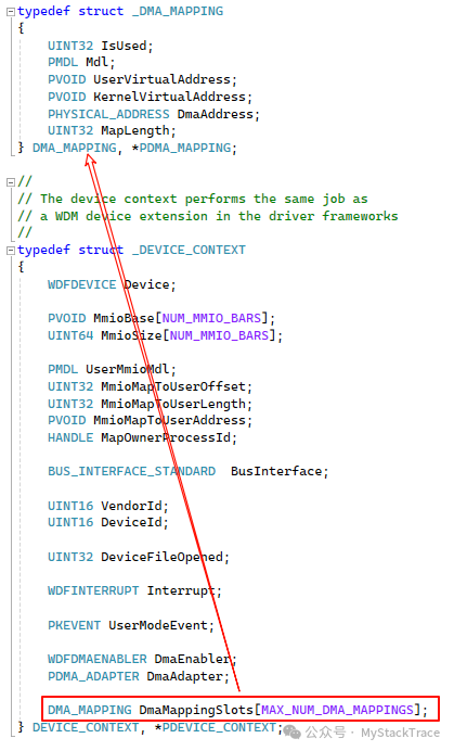 Below is the implementation of the function MapDmaBuffer. Before helping user mode perform DMA, the driver needs to allocate a free DMA mapping slot to record the relevant information of this mapping. Here, we use atomic operations (CAS or cmpxchg) to avoid conflicts when multiple threads perform DMA mappings simultaneously. To perform DMA mapping in kernel mode, we first need to obtain the physical memory behind this user-mode virtual memory. Following the consistent practice of the Windows kernel, we need to allocate an MDL for this user-mode virtual address. At this point, the MDL does not contain information about the physical memory, and we still need to use a well-known Windows kernel function MmProbeAndLockPages to obtain the physical memory corresponding to this user-mode virtual memory. If some physical memory has not been allocated (never accessed, no page fault has occurred), it will be allocated and a mapping relationship will be established. This function also serves to lock the physical pages behind this virtual memory, preventing the operating system from swapping them out, as these physical pages are about to be used for DMA transfer. If not locked, the operating system may swap them out for other uses, while DMA may be writing to or reading from these pages, which could lead to unpredictable errors. Therefore, whether on Windows or Linux, it is necessary to lock the corresponding physical pages before performing DMA to prevent them from being swapped out. After the Probe and Lock actions, the MDL will contain all the physical page information for this user-mode virtual memory. We then need to use the kernel function MmGetSystemAddressForMdlSafe to obtain the kernel-mode virtual address mapped by this MDL. If it is not yet mapped, this function will map it to the kernel-mode virtual address space and return the mapped address. This step is necessary because the following DMA operation using the DMA adapter:CreateCommonBufferFromMdl requires that this MDL has already been mapped to the kernel-mode virtual address space.The CreateCommonBufferFromMdl function on the DMA adapter is a callback function that can create a “Common” buffer based on an MDL and map this MDL to a DMA address, allowing both the CPU and the device’s DMA to access this buffer. This function has a limitation: when the system does not enable IOMMU and DMA remapping, the physical pages contained in this MDL must be contiguous, as in this case, the DMA address is the physical address, and this function can only return a DMA address, thus requiring the physical addresses to be contiguous. However, if the system enables DMA remapping, the physical pages in the MDL can be non-contiguous, as the IOMMU maps these non-contiguous physical pages to a contiguous logical address through the IOMMU page table, which is the DMA address we need. This is why we prefer to use the DMA adapter instead of directly using the physical page addresses in the MDL for DMA; the DMA adapter helps us interact with the system’s IOMMU. Finally, when the function MapDmaBuffer obtains the DMA address, it will place this address in the output buffer of the IOCTL provided by user mode, allowing the application to obtain the DMA address corresponding to this user-mode virtual address.
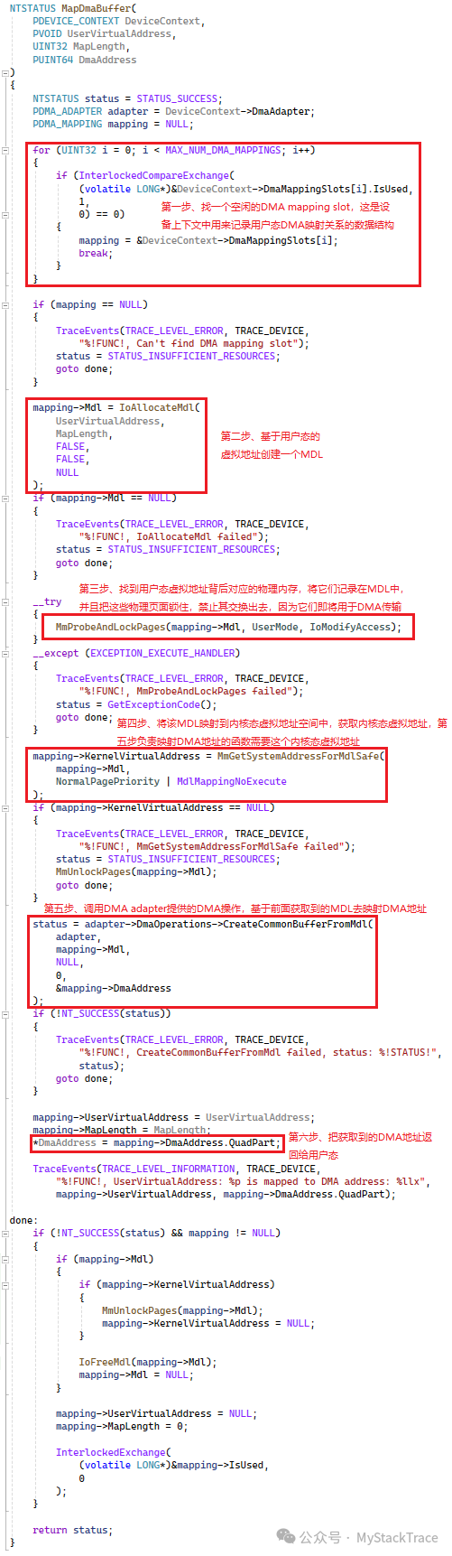 It is important to note that the DMA operation CreateCommonBufferFromMdl used in step five of the above MapDmaBuffer requires that the DMA version be specified as 3 when creating the DMA Enabler. Therefore, we need to specify this in the structure WDF_DMA_ENABLER_CONFIG when creating the DMA Enabler object. If this is not done, the callback function CreateCommonBufferFromMdl will be null.
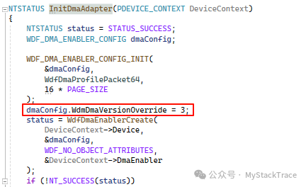 Next is the implementation of UnmapDmaBuffer. First, we need to find the matching mapping relationship in the DmaMappingSlots maintained in the device context based on the DMA address provided by the application. After finding it, we first use the DMA operation on the DMA adapter: FreeCommonBuffer to release this “Common” buffer, unmapping the relationship between the DMA address and this physical memory. Then the corresponding MDL is freed, and we can unlock it (which is the opposite of the previous Lock operation) and release it. After completing these steps, we can reclaim the corresponding DMA mapping slot.
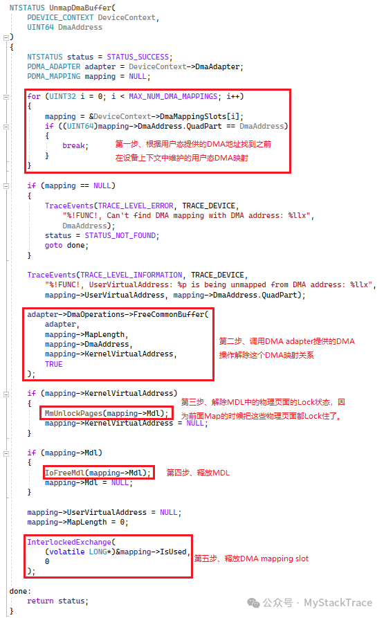 The changes to the driver are as described above. Next, let’s look at how to write an application to interface with the driver. Our approach is that the application first needs to map the MMIO registers of this PCIe device to the user-mode virtual address space, allowing us to configure the registers related to vector addition in user mode. Then, we need to create an event and inform the driver of this event through IOCTL, allowing the driver to record the kernel-mode object pointer corresponding to this event. Later, whenever an interrupt occurs, this event will be notified, and the user-mode application will receive the interrupt notification. We have already introduced these two points in previous articles, so we will not elaborate on them here. We will place these operations in the main function and encapsulate the focus of this implementation: testing the vector addition functionality of the PCIe device into the function TestVectorAdd.Below is the implementation of the main function of the application: it includes opening the PCIe device file, mapping the MMIO to user mode through IOCTL, creating an interrupt event, sending the event handle to the driver through IOCTL, and then calling the function TestVectorAdd to test. After the test, various resources are cleaned up.
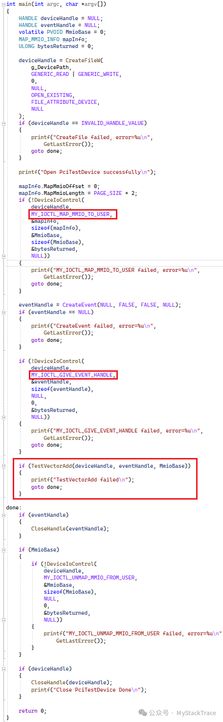 Next, let’s discuss the implementation of the function TestVectorAdd. Since the DMA of the PCIe device we simulated only supports contiguous DMA addresses (usually physical addresses), and we cannot directly allocate contiguous physical addresses in user mode, we allocate a page-sized memory for each vector, ensuring that the starting address is aligned to the page size to avoid crossing physical pages, ensuring that each vector occupies a complete physical page. After allocating memory for the vectors, we can use the previously implemented IOCTL request Map DMA Buffer in the driver to obtain the DMA address corresponding to each vector. We then initialize these three vectors: the first vector is filled with byte 1, the second vector with byte 2, and the third vector, which is the sum vector, is initialized to 0. Next, we configure the vector DMA address register and the vector addition control register using the user-mode MMIO register address obtained earlier, and notify the PCIe device to start executing the vector addition operation through the Doorbell bit of the vector addition control register. At this point, the interrupt event created in the main function comes into play; we make the program wait on this event. When the PCIe device completes the vector addition, it will trigger an interrupt, and the driver’s interrupt handler will be called, notifying this event, which in turn wakes up the user-mode program. The user-mode program will then read the interrupt status register to check if this interrupt is the one indicating the completion of the vector addition. If so, it exits the loop, clears the interrupt status register, and finally verifies whether the vector addition performed by the PCIe device is correct. After the test, it cleans up the DMA mapping and releases the memory.
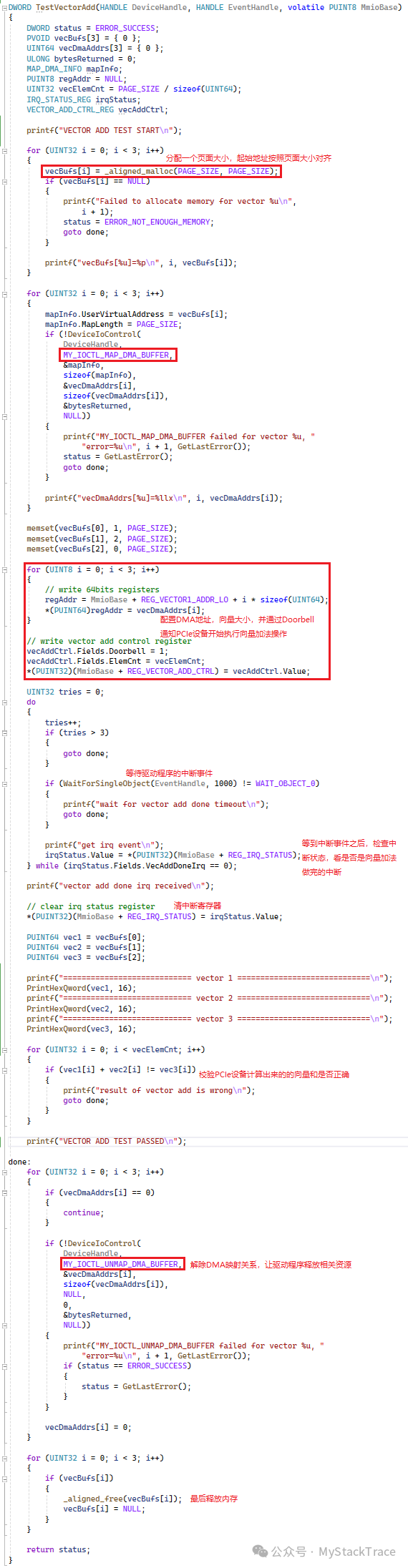 Below are the results of running the application test. It can be seen that the test program successfully obtained the DMA address and also received the interrupt indicating the completion of the vector addition, and the sum vector calculated by the PCIe device passed the verification of the test program.
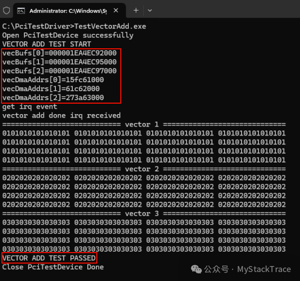 Below is the log output from the driver during the test process, showing that the user-mode virtual address and the corresponding DMA address printed are consistent with the values printed in the application.
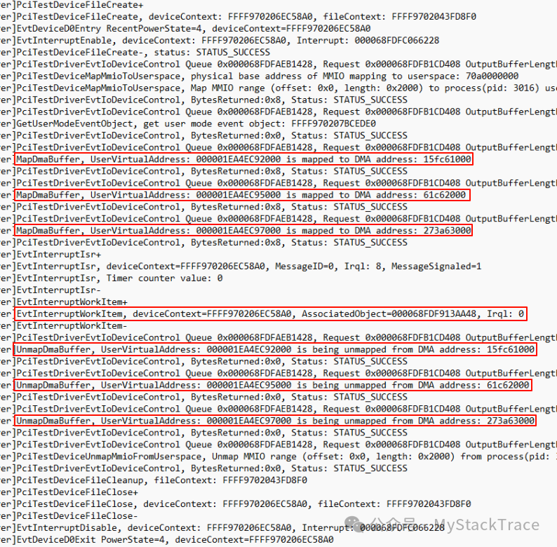 This is an example of accessing hardware device DMA from user mode. Although there are limitations (a DMA buffer can be at most one page size), it illustrates the point. We will continue to improve the DMA functionality of this PCIe device to support non-contiguous physical addresses.