
Project Name: WiFi Smart Socket with Magnetic Latching Relay
Author: oldfox126
Introduction
Yesterday’s article did not get much increase in views, but there was a lot of interaction in the comments section. I saw the enthusiasm of my true fans (freeloaders), so I decided to add more content today on the weekend.
Despite being affected by Typhoon “Sempaka,” I continue to work hard at my job. Please do not hesitate to give likes and comments to support me.

Project Overview
This project utilizes a WiFi smart socket with a magnetic latching relay, which has excellent energy-saving performance. The overall power consumption is only about 0.65W, and it can be used for a long time without causing the relay coil to heat up. It also supports MQTT and OTA firmware upgrades.
The project is improved from: 【Secondary Testing】 Smart WiFi IoT Socket. Thanks to the original author @御坂0x1BF52.
Main Hardware Improvements
1. The relay is replaced with a magnetic latching relay: HF3F-L-05-1HL1T (standard polarity / 1 set normally open / single coil / 5V / 4 pins). The advantage is energy saving; it only needs power for a moment to start or stop the relay, and no power is needed to maintain the state afterward.
Therefore, this socket has excellent energy-saving performance, with an overall power consumption of only about 0.65W, and long-term use will not cause the relay coil to heat up.
Additionally, during the process of the socket losing power and being re-powered, the magnetic latching relay will not engage or release unnecessarily (which cannot be avoided with ordinary relays), allowing the socket to maintain the state prior to power loss.
2. Using ESP12S (ESP12F can also be used), LED display and relay control are separated, allowing the LED to show more statuses.
The original plan used ESP01S, but it did not have extra IO ports for LED display, so the LED and relay had to share the IO2 port.
ESP01S has a FLASH capacity of only 1M, which is indeed too small. ESP12S has a capacity of 4M, making OTA firmware upgrades possible.
3. A new board was designed for dual-sided insertion of ESP12S. In the original plan, the soldered pins of ESP01S occupied the bottom space of the integrated socket, preventing it from sitting flat.
4. The socket has been raised by about 0.5mm to avoid occupying the space below the relay in the original plan.

Main Software Improvements
1. Instead of using the Blinker library, I switched to MQTT, mainly because the Blinker APP can only create 5 devices, which is not enough.
2. The programming environment was changed from Arduino to vscode + PlatformIO + C++, as vscode’s programming environment is very user-friendly.
3. Initially, the software used microPython (which is indeed simpler), but later I found that the resources for microPython were still too limited. Halfway through the project, I could not find the smartConfig code and had to start over in C++.
Main Software Features
1. Supports web network configuration 2. Supports WeChat QR code network configuration 3. Supports NTP for time synchronization 4. Supports MQTT, which helps to understand the working mechanism of IoT more thoroughly. You can turn the socket on or off using the switch, countdown timer, or timer on the MQTT mobile app.
5. The timer program is implemented locally on the socket, not on the cloud. As long as parameters are submitted and saved, even if the network is later disconnected, the socket can still be turned on or off at scheduled times. Therefore, it is possible to physically restart the modem or router using this socket. 6. Supports OTA firmware upgrades online, allowing firmware upgrades over the network without the pain of disassembling the board to reflash the firmware. 7. Supports LittleFS file system, which can save various parameters even when powered off. Even if the socket loses power and restarts, the original parameters remain intact.
Source of Related Components
To avoid suspicion of advertising, I won’t elaborate too much here. If needed, please check the original project.
Software and Hardware Installation Steps
1. First, flash the firmware onto the ESP12S.
2. Configure the network for the ESP12S and set the MQTT parameters.
3. Install the MQTT APP on your phone and set up the server parameters.
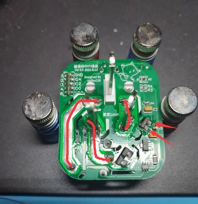
4. Solder the ESP12S onto the module, solder it onto the PCB socket body, install the components, and then solder the ESP12S module onto the main PCB.
At this point, it is sufficient to solder the integrated socket (the part marked in red) last; additionally, at the position indicated by the blue arrow, solder 2 Dupont wires for 5V (red) / GND (black).

5. Power the ESP8266 development testing rack / programmer with 5V (red) / GND (black) and connect the 2 Dupont wires from the previous step.

Test the power to see if the MQTT APP can display the changing time normally (indicating that the ESP12S module is soldered correctly, connected to Wi-Fi, and linked to the MQTT server); whether the switch responds normally (the LED will light up and down with the switch); and use a multimeter to check whether the relay output can be controlled by the MQTT APP switch, turning on and off normally.

6. After passing all the above tests, it indicates that the socket’s software and hardware functions are normal. You can turn off the power and solder down the 2 Dupont wires, and solder the integrated socket.
7. Once everything is soldered correctly, you can assemble the casing.


Circuit Design Showcase

Schematic Diagram

PCB Diagram

3D Diagram
BOM

Project Attachments
There are many project attachments; it is recommended to download and check from the original project.
If you have any other questions, you can leave a message to the author at the bottom of the original project.
Please click “Read the Original” to view the original project.
It seems that the introduction has covered most of what I wanted to say; there is not much else to discuss.
So I wish everyone a happy weekend, and those in South China (Guangdong, Guangxi, Hainan) should pay attention to typhoon prevention.

Previous Open Source Recommendations
Campus Lecturer
 In July, in the wind and rain, “Campus Lecturer” is waiting for you
丨More
School-Enterprise Cooperation
School-enterprise cooperation is only one joint laboratory away
丨More
Training Camp Collection
Collection of excellent open-source projects based on CW32
丨More
DIY Creative Projects
Voltage Tester / High Voltage Megohmmeter / Transistor Voltage Tester
丨More
Case Recommendations
[Analog Circuit] RDA5807 FM Radio Design
丨More

Follow me
I aspire to make you an excellent hardware engineer!

Repost

Collect

Like

View