Siemens Comprehensive + Portal + EPLAN Electrical Drawing Video Recording for Sale at Low Price!
Chuangkong Education Siemens Comprehensive Class Course Introduction
1. The Origin of CANopen: Where Did CANopen Come From?
The CAN protocol was developed by Bosch in Germany in 1983 for network communication in automotive drive systems. It is now known as the international standard ISO11898, and CANopen is drafted and reviewed by the non-profit organization CiA (CAN in Automation). The basic CANopen devices and communication sub-protocols are defined in the CiA draft standard 301. Specific device sub-protocols are expanded based on CiA 301, such as CiA401 for I/O modules and CiA402 for motion control.
2. Advantages of CANopen Hardware?
The most prominent feature of the CAN protocol is error detection, limitation, and handling. When a CAN device detects a bus error, it rejects the previously received bit sequence and sends an “error frame,” which is entirely handled by the CAN chip itself without requiring human programming.
It supports multiple masters, similar to Profibus DP, where each device on the bus is both a master and a slave, eliminating the need for manual arbitration, making it convenient for users to develop.
With a short frame structure, CAN messages typically consist of only 8 bytes, giving them an inherent advantage in anti-interference capability. To explain why a short frame structure is better at resisting interference: if the communication message is long, the time taken to send a frame is also long, and if interference occurs, all the effort put into sending a message may result in the other party not receiving it due to interference, leading to frustration.
It is cost-effective; CAN peripherals can be found on most mainstream chips today, with MCUs costing around 20 yuan supporting CAN peripherals, some even supporting two CAN interfaces. This is aided by CiA’s active promotion.
3. Advantages of CANopen Software?
CANopen is mainly promoted by CiA, a non-profit organization. There is a wealth of CANopen protocol documentation available online for anyone to download. Commonly used documents include DS301 (Draft Standard), DS402, and almost every CAN enthusiast has a copy, like a treasured martial arts manual.
There are many open-source projects for CANopen protocol development, with CanFestival being one of them. I have ported it to the Beike MT4414TE-CAN touchscreen used on an 8-bit microcontroller. This source code is somewhat resource-intensive, and many streamlined codes based on MCUs are available online.
Developing a complete CANopen protocol stack is a challenging task, and doing it well is very difficult. The difficulty lies in your understanding of the CANopen protocol, such as EMCY, resetting nodes, whether “NO Initialization” is needed, heartbeat, and how to handle Node guard. This cannot be considered an advantage.
4. Why Are So Many Companies Promoting CANopen?
CANopen is an excellent communication protocol for motion control, adopting some object-oriented design concepts, such as object dictionaries, Process Data Objects (PDO), and Service Data Objects (SDO).
CANopen has become the most common protocol in Europe, and any automation company has a CANopen communication interface, making it a standard feature. Standard features do not mean they are inferior; they simply indicate a better cost-performance ratio. CANopen defines a complete synchronization control mechanism, making it a mainstream motion control protocol. In addition to operating on the CAN bus, it has also been adapted to Ethernet (CANopen over Ethernet), forming the well-known PowerLink and EtherCat industrial Ethernet protocols.
To elaborate a bit more, the so-called motion control bus standards are of little significance because motion control technology is held by various manufacturers. Every slightly larger manufacturer has its own dedicated motion control protocol, such as Mitsubishi’s SSCNET, Yaskawa’s MECHATROLINK, Beckhoff’s CANOPEN and EtherCat, Schneider’s CANopen, Siemens’ SiMotion, B&R’s PowerLink, and Bosch Rexroth’s SERCOS.
Due to the advantages of CANopen (see DS402, servo control standards) in motion control, especially synchronization control, even second- and third-tier manufacturers incorporate their elements into motion control systems, leading to typically closed motion control systems with little interconnectivity. In fact, achieving interconnectivity is also very challenging.
Second- and third-tier manufacturers develop their own CANopen protocols based on their needs and adapt them to different physical layers, forming their motion control systems. The performance quality depends on their understanding of the CANopen protocol.
Basics: Nine Obscure Concepts in the CANopen World
1. DCF
This is the configuration (Config) data archive file for the CAN network. Its function is minimal, as there is this option in Codesys software.
2. EDS
The Electronic Data Sheet describes the attributes and parameters of a slave device and serves as a description of the slave device’s object dictionary. For example, if the internal parameters of a servo drive (each parameter corresponds to a position in the object dictionary determined by index and sub-index) remain unchanged, its corresponding EDS file will not change. It is worth mentioning that not all master controllers need to use EDS; for instance, Beckhoff does not require it, as it needs you to be familiar with CANopen DS301 and DS402 for manual alignment configuration; Beike FD and JD servos follow the DS402 standard to formulate EDS files, allowing users to configure directly, thereby reducing development cycles.
3. Reset Node
When a device encounters an anomaly (e.g., a slave disconnecting and then reconnecting, tested with M258 on Beike FD servo), the master controller sends a “reset node” command. The Beike ED servo resets the node, restoring the driver to factory settings, including resetting the CAN communication parameters to default values. For FD and JD servos, all configuration parameters except CAN communication parameters are restored to factory settings.
4. EMCY
This is an emergency message; when a slave, such as a servo, loses power, it sends an emergency message to inform the master controller of its status. Generally, a servo can send this message after power loss due to its capacitor charge.
5. Heartbeat and Node Guard
Configure heartbeat parameters, set heartbeat cycle, and heartbeat consumer time. This consumer time acts as a timeout parameter. The master station starts timing upon receiving a heartbeat, and if the next heartbeat is not received within the timeout period, it considers the slave offline and reports an error, handling it according to the user’s configured error handling method.
Each node in the network can configure heartbeat; the master can listen to the slave, the slave can listen to the master, and the slave can also listen to other slaves. Here, there is a producer-consumer concept, where devices on the bus define themselves as either heartbeat producers or consumers. Producers generate heartbeats, consumers listen for heartbeats, and then respond accordingly when an anomaly is captured.
I personally believe the heartbeat’s function is minimal; for instance, if a device disconnects and reconnects while using the homing function of a servo, the position changes upon power cycling. This situation has led to instances where, in some customer applications, the response is to quickly disconnect power and restart.
Node guard functions similarly to heartbeat but can read the CANopen communication status of slave devices (initialization, pre-operational, operational, stopped), falling under the category of DS301.
6. Differences Between DS301 and DS402
DS301 is a communication protocol stack, while DS402 is a higher-level protocol built on DS301, belonging to servo control protocols. The protocol defines the role of each object dictionary value; for example, 0x6040 is the control word. DS402 defines all the functions a servo should have, and manufacturers can develop according to the protocol definition.
7. Object Dictionary
From a software perspective, the object dictionary is essentially a collection of data structures. It can be understood as a book, and the behavior guidelines for CANopen devices must reference this book. Regardless of what it does, a device must consult the object dictionary before deciding whether to act. For instance, it must refer to the object dictionary regarding when to send TPDO, which requires checking the corresponding transmission type and Event timer in the object dictionary. Additionally, the principles of PDO mapping involve querying this book to see what content is written there before sending that content as PDO.
For example, if your program receives a CAN message, and since the accessible object in the object dictionary is SDO, you must first determine whether it is an SDO object. Then your program needs to look up the object dictionary using the index and sub-index specified in the SDO (a sorted collection of data structures) to find the corresponding object and perform actions as instructed in the SDO, such as assigning a value to a variable in the dictionary.
8. SDO
This is straightforward; it resembles a one-to-one communication mode like serial communication, where the master sends a request frame, and the slave replies with a response frame.
Here are a few examples for clarity:
To write the 1 byte data: 0xFD in the object dictionary of node 5, at index 0x1400, subindex 2, send:
605 2F 00 14 02 FD 00 00 00If successful, node 5 responds:
585 60 00 14 02 00 00 00 00To write the 4 bytes data: 0x60120208 in the object dictionary of node 5, at index 0x1603, subindex 1, send:
605 23 03 16 01 08 02 12 60If successful, node 5 responds:
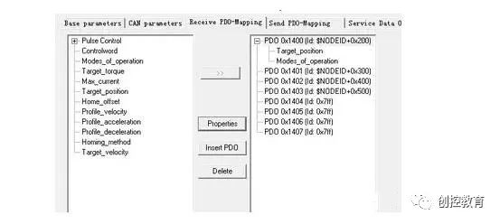
585 60 03 16 01 00 00 00 009. PDO
It is divided into TX-PDO and RX-PDO.
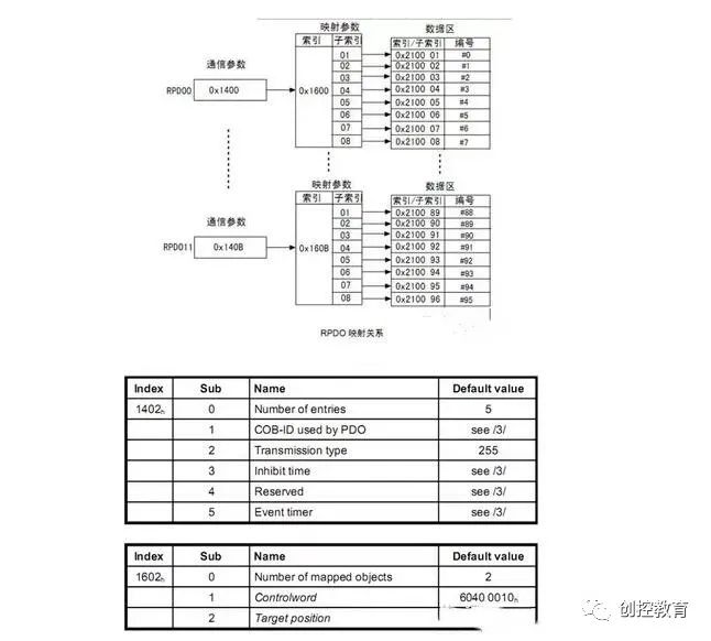
The above image shows the PDO configuration process, with 0x1402 (receiving PDO communication parameters), including the COB-ID used by PDO, transmission type, Inhibit time, and Event Timer.
0x1602 (mapping objects), in the above example, maps to Control word and Target position.
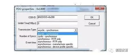
Here, I want to emphasize the Transmission Type; the following are the centralized methods supported in Codesys:
acyclic sync (value 0): synchronized PDO, with synchronization defined by the specific device protocol
Cyclic sync (value 1-240): synchronized PDO, sends PDO after every N SYNC cycles
Sync rtr (value 253): synchronized PDO, sends PDO upon receiving a remote frame request
Async (value 254): asynchronous PDO, sends PDO upon receiving a remote frame
The last two Async (254, 255) are defined by the device manufacturer and are the most commonly used methods. When an event occurs, they send. Manufacturers generally use the data change method for sending; both FD and JD servos use the same method, sending upon data change. It is essential to set the “Inhibit time” to reduce CANOPEN communication bandwidth.
Specific Case
The master controller writes target position and mode of operation to the servo; the COB-ID for this PDO is 0x200 node ID. The transmission method is 255 or 254, with an inhibit time of 100, which is 10ms.
(Content sourced from the internet; copyright belongs to the original author)
Disclaimer: If there are copyright issues, please contact for deletion!Neither individuals nor organizations bear any legal responsibility.
Siemens Comprehensive + Portal + EPLAN Electrical Drawing Video Recording for Sale at Low Price!
Chuangkong Education Siemens Comprehensive Class Course Introduction