During the development phase of CAN chips, various issues related to communication error management need to be validated. The ISO-16845 international standard specifies comprehensive testing standards, such as error frame detection, transmission frame-related detection, and error management logic validation. This article mainly shares effective and convenient methods to complete the testing.
Traditionally, to simulate CRC errors, ACK errors, bit stuffing errors, and other situations in CAN frames, some solutions use pulse power to simulate the entire CAN frame sequence to create partial bit errors, which is complex and prone to setup errors, failing to achieve the desired effect, and cannot determine the active or passive error state.This article introduces how to use the ZhiYuan Instruments ZPS-CANFD-S1 bus analyzer to complete the relevant testing work.
Introduction to ZPS-CANFD-S1 Bus Analyzer
The ZPS-CANFD is the second-generation CAN bus development auxiliary tool from ZhiYuan Instruments, suitable for measurement and testing of CANFD, CAN, and LIN buses. It supports the sending and receiving of bus data, high-level protocol analysis and diagnostics, and can collect and record the physical layer electrical signals of CANFD and CAN buses in real-time. It also includes high-speed simulation channels, allowing users to easily construct bus signal measurement and analysis, node function simulation and testing, and network reliability diagnostics through the provided hardware interface and ZVIEW software functionalities.
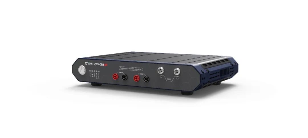 Figure 1: ZPS-CANFD-S1 Bus Analyzer
Testing Scheme Introduction
For this test, we mainly use the ZVIEW software, which has many functions. We primarily utilize the “Active Send Interference” and “Passive Receive Interference” features, combined with the software’s message logic analysis and other auxiliary functions, to easily and intuitively achieve our expected testing results.
1. Active Send Interference
In the “Active Send Interference” function, we can customize the message structure, error types, etc., and can simulate any position of any frame message. As shown in the figure below, we can interfere with any position (i.e., the gray selected area) of the message to be sent to achieve the purpose of sending erroneous messages, thereby validating the chip’s action mechanism after receiving erroneous messages.
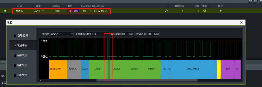
Figure 2: Active Send Interference
In short, through this function, we can send any desired message, significantly simplifying the preparation work required for testing, greatly improving efficiency, and solving the difficulties of testing.
2. Passive Receive Interference
The core difference of this function from “Active Send Interference” is that it interferes with the normal messages sent by the device under test, turning them into erroneous messages, and then feeds back to the device what erroneous messages it sent, observing whether its response is normal under this condition, such as common CRC check errors, ACK errors, etc.
Similar to “Active Send Interference”, this function also allows you to select the interference range to interfere with the selected area, thus achieving continuous interference with the messages.
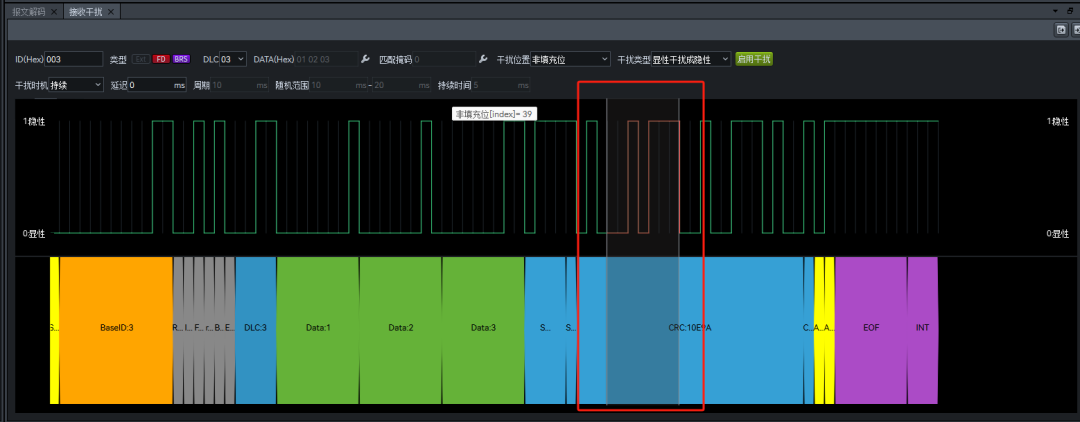
Figure 3: Passive Receive Interference
The “Passive Receive Interference” function, in addition to the above uses, is also often used in BUSOFF recovery time testing, and the ZVIEW software also provides this testing function.
3. Other Related Functional Applications(1) Error Counter Management: Used to control whether the device is in an active error state or a passive error state;(2) Sampling Point Testing: To determine whether the sampling point positions set in the software are reasonable and correct;(3) CAN Logic Decoding: Provides complete CAN waveform and logic decoding data, allowing synchronous observation of message waveforms, with all information clear at a glance;(4) Bus Level Measurement: Multiple measurements, averaging, to observe whether it meets standards;(5) Bus Bit Time Measurement: Multiple measurements, averaging, to observe whether it meets standards;(6) Bus Edge Measurement: Multiple measurements, averaging, to observe whether it meets standards.
Conclusion
The ZPS-CANFD-S1 has excellent platform hardware performance. Based on years of CAN research and testing experience, ZTMI has developed various CAN testing functions to meet testing needs in different scenarios. In the current context of continuously evolving testing requirements, ZTMI ZhiYuan Instruments also welcomes users to propose new testing needs to strengthen technical cooperation and collaboration for mutual growth.
# A Few Words
If you have any questions or suggestions regarding us, please feel free to provide feedback to the suggestion box. Every word you say will reach the relevant person in charge!

Long press to identify and go to the suggestion box