(⊙o⊙)…, I am sharing Arduino-related materials again. For some, it might be incomprehensible but impressive. But who told me I have been tinkering with Arduino recently~~~~
1. Monochrome LED Module
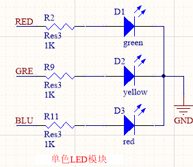
Figure 1 Monochrome LED Module Schematic
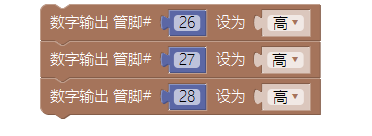
As shown in Figure 1, RED corresponds to red, GRE to green, and BLU to blue, corresponding to digital pins 26, 27, and 28, respectively. When using, simply set the corresponding pin to output high level.
The example implementation for lighting up the red, green, and blue lights is as follows:
2. 8-Way LED Flow Light Module
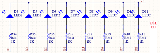
Figure 2 8-Way LED Light
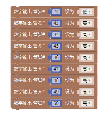
As shown in Figure 2, the cathodes of the 8-way LED lights are connected to Y0, and the anodes of the 8 LED lights are connected to D1, D2, D3, D4, D5, D6, D7, D8 respectively, where Y0 corresponds to digital pin 24, and D1~D8 correspond to digital pins 43~50.
The example implementation for lighting up the 8 LED lights is:
3. Single/Double Digit Display Module
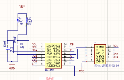
Figure 3 Display Module Schematic
As shown in Figure 3, the four-digit common cathode display module uses I2C communication to display. Users do not need to understand the hardware and program principles deeply, as Mixly has provided a packaged module for direct use. When displaying a single character, it can be treated as a unit digit display, and when displaying two characters, it can be treated as a double digit display.
The example implementation for displaying the character “1234” on the four-digit display is:

4. Infrared Receiver Module
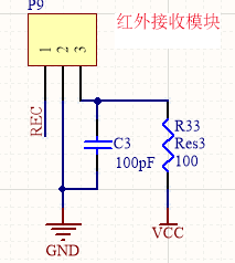
Figure 4 Infrared Receiver Module Schematic
The infrared receiver module needs to be used with an infrared remote control. It can receive infrared signals emitted by the remote control (different keys pressed correspond to different infrared signals). When a key on the remote control is pressed, the infrared receiver receives the corresponding signal and sends it to the CPU through pin REC (digital pin 36). Note: When using the remote control, the film below needs to be removed, and when not in use, the film should be inserted to prevent automatic discharge.
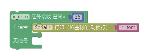
The example implementation to print the received infrared signal value via serial is:
5. Full-Color LED Module
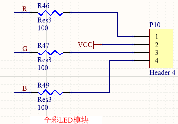
Figure 5 Full-Color LED Module Schematic
Any color in nature is composed of three primary colors (red, green, blue), so a full-color LED can display any color through programming. As shown in Figure 5, the common terminal of the full-color LED is connected to the power supply, and R, G, B are connected to the CPU’s PWM pins (pins 4, 2, 3). Regarding PWM knowledge, participants do not need to understand it deeply; if needed, they can search it on Baidu. Below, we will focus on how to achieve different color displays and how to adjust the brightness of the lights.
It can be simply understood as: PWM output pins divide the power supply voltage into 0—255 (a total of 256) levels. For example, when the R pin (pin 4) outputs 0 and G (pin 2) and B (pin 3) output 255, it represents that the brightness of the red light reaches the maximum while the other colors are off. When the R pin (pin 4) outputs 255 and G (pin 2) and B (pin 3) output 0, it represents that the brightness of the red light reaches the minimum while green and blue reach the maximum. Thus, we can change the output values of the corresponding pins to change the brightness of the LED. When we need to display different colors, we can control R, G, and B to output different values. For example, setting R and G to 0 and B to 255 will light up yellow (because red plus green equals yellow).
6. Analog Sound Sensor Module
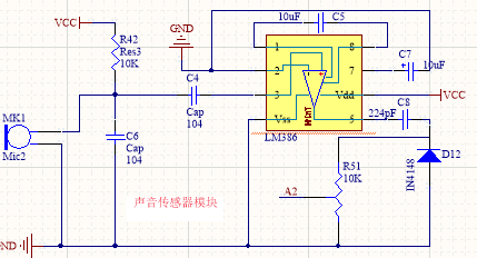
Figure 6 Sound Sensor Module
The sound sensor module can convert the sound signal received by the microphone into a continuously varying voltage signal (analog signal), which can be detected by the CPU’s analog pin A2. Below is a simple introduction to the detection principle of the analog signal:
The analog voltage range is 0~5v, and this voltage value is divided into 0~1023 (a total of 1024) levels in the CPU’s analog port, where an analog voltage of 0v corresponds to a digital value of 0, and an analog voltage of 5v corresponds to a digital value of 1023. When there is sound, there will be an analog voltage value corresponding to the intensity of the sound (the louder the sound, the larger the voltage value), and the analog port will convert this analog voltage value into the corresponding digital value, thus achieving sound signal detection.
Note: Never short-circuit the power and ground of the development board, or it may cause the sound module to fail.
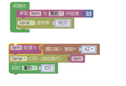
The example implementation to detect environmental sound values and print the sound value via serial every 0.5 seconds is:
7. Temperature Sensor Module
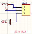
Figure 7 Temperature Sensor Module Schematic
The temperature sensor can output a varying analog voltage based on temperature changes (the higher the temperature, the larger the voltage value). This analog voltage can be detected by the CPU’s analog pin A1 (the detection principle is the same as that of the sound sensor module), and Mixly has provided a packaged module for direct use.
Note: Never short-circuit the power and ground of the development board, or it may burn the temperature sensor.
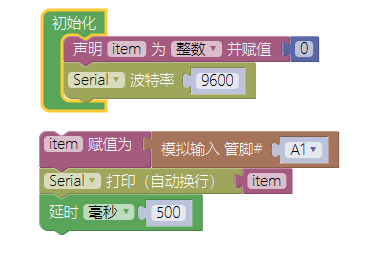
The example implementation to detect environmental temperature and print the temperature value via serial every 0.5 seconds is:
8. Rotary Potentiometer Module
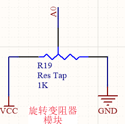
Figure 8 Rotary Potentiometer Module
The schematic of the rotary potentiometer is shown in Figure 8. When the potentiometer is turned, its output terminal will output a continuously varying analog voltage, which can be detected by the CPU’s A0 port (the detection principle is the same as that of the sound sensor).
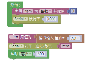
The example implementation to detect the value of the rotary potentiometer and print it via serial every 0.5 seconds is:
9. Tactile Switch Module
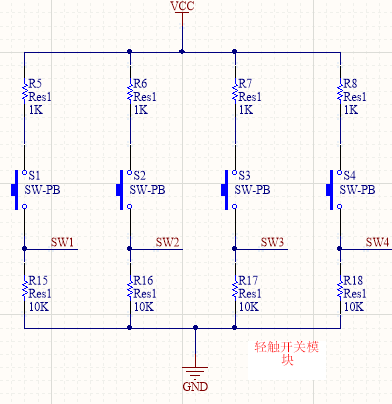
Figure 9 Tactile Switch Module Schematic
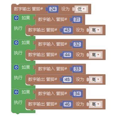
As shown in Figure 9, this module has four tactile switches: SW1, SW2, SW3, SW4, corresponding to digital pins 31~34. When the switch is not pressed, the digital pin is at a low level. When the switch is pressed, based on the voltage divider principle with a resistor in series, the digital pin is at a high level.
The example implementation for controlling four LED lights with four switches is:
10. Buzzer Module
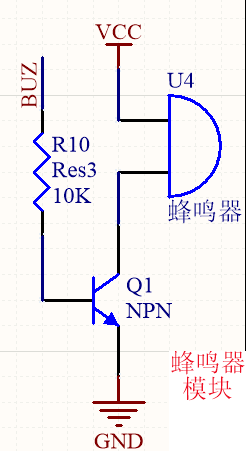
Figure 10 Buzzer Module Schematic
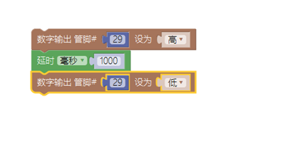
As shown in Figure 10, when BUZ is at a high level, the transistor conducts, and the buzzer sounds. When BUZ is at a low level, the buzzer does not sound, where BUZ corresponds to digital pin 29.
The example implementation to make the buzzer sound at a frequency of 1 second is:
11. LCD1602 Display Module
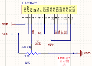
Figure 11 LCD1602 Display Module Schematic
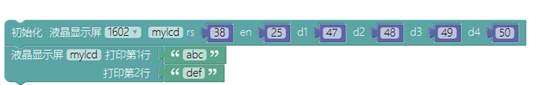
LCD1602 is a liquid crystal display that can display two lines of characters, with each line capable of displaying 16 characters. In Mixly, there is a packaged module for direct use.
The example implementation to display the strings “abc” and “def” on two lines is: