In previous sections, we used the GPIO output function for the LED lights. This time, we will finally need to use the GPIO input function. The human infrared sensing module is quite simple to use. After completing our experiment, we will combine it with the previous buzzer to create a simple human detection alarm.
1. Introduction to HC-SR501 Sensor Module
We use the HC-SR501 model infrared sensor to detect human presence. For more detailed parameters, refer to the module’s user manual.

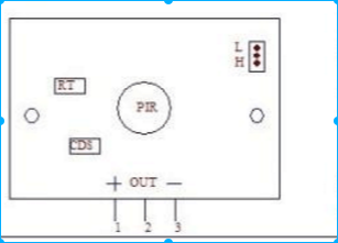
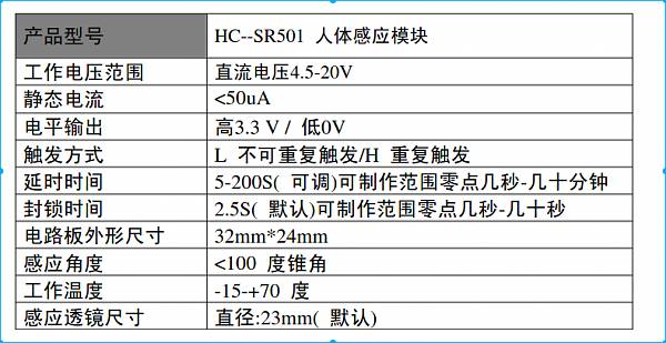
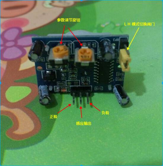
Referencing the previous parameters and circuit diagram, find the positive and negative pins on the left and right, with the middle PIN being the sensing output. When a human is detected, it outputs a 3.3V high level; when no signal is detected, it outputs 0. The working voltage should be between 4.5V-20V. The Raspberry Pi’s P1 number 2 and 4 pins provide 5V, which meets the requirements, so we will connect to the 5V supply.
The parameter adjustment knob is used to control some parameters, such as detection delay time and sensitivity, etc. We will use the default values here.
However, there is a key L-H mode adjustment valve to introduce. In the upper right corner, there are three pins; assuming they are numbered 1, 2, and 3 from top to bottom. There is also a yellow connector that connects pins 2 and 3, representing H mode. This connector can be unplugged and connected to the top to connect pins 1 and 2, representing L mode.
L mode cannot be triggered repeatedly; when a human is detected, it outputs a high level for a certain time and then returns to low level. During this time, if a human is still detected, it does not extend the high level duration. Only after the low level lock time (default is 2.5 seconds) has passed does it start detecting again.
H mode can be triggered repeatedly; if a human is continuously sensed, it will output a high level until no human is detected, then maintain a low level for a short time before returning to low level.
2. Pull-Up and Pull-Down for GPIO Input
For those learning software, the software world consists only of 0s and 1s, so I thought so before encountering hardware. When using the human infrared sensor, I encountered a problem; I thought that as long as I set the GPIO mode to INPUT, I could just read the pin’s status as 0 or 1. However, I encountered an issue. When I set pin 22 (WiringPi number 6) to INPUT mode and connected a wire, with the other end not connected, it should theoretically read 0V. However, I found that it did not remain low; instead, it fluctuated between high and low. When I held the other end, it output high. When I connected pin 3 (WiringPi number 8), it remained high. I had to look up various materials and discovered the concepts of pull-up and pull-down.
When we connect a pin to GND, it is low; when we connect a pin to 3.3V, it is high, and the state is clear. If we connect nothing, the pin is in a floating state, easily affected by external interference, possibly high or low, or in a state between high and low. At this point, we need to specify whether the pin should be high or low, preventing it from being in a floating state. Connecting a pull-up resistor can ensure the pin is in a clear high state, while connecting a pull-down resistor can ensure it is in a clear low state. Previously, when we used it for output, we explicitly defined the output state. There is a well-written English explanation about pull-up and pull-down resistors, which I also referred to; you can test it with the Raspberry Pi as well. (http://www.bit-101.com/blog/?p=3813).
PIN3 remains high because this PIN is used for Raspberry Pi I2C devices and has a physical pull-up resistor connected internally. Therefore, its state is always high, and this PIN cannot be used as INPUT.
PIN22 fluctuates between high and low due to being in a floating state. Therefore, to use this PIN, we need to specify whether it should be high or low when floating. WiringPi controls this variable through pullUpDnControl.
3. Wiring and Testing
The left pin 1 of the module connects to P1 pin 2 for the positive 5V, the right pin 3 connects to PIN6 for the negative, and the middle pin 2 output line connects to PIN22 (WiringPi is marked as 6). The wiring diagram is as follows: 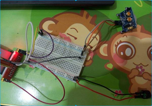
In the diagram, I also connected the buzzer. When we detect a human, we will use the beep function from the previous section to emit a warning sound.
First, we will preliminarily check if the module is functioning correctly by testing the HC-SR501 in different modes.
Choosing H mode, the connector connects to the bottom two pins, meaning it can be triggered repeatedly; when a human is detected, it remains high.
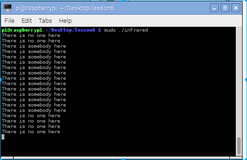
It can be seen that the middle is continuously detected, meaning the high level duration is extended with human activity.
If we select L mode, the connector connects to the top two pins, meaning it cannot be triggered repeatedly; when a human is detected, it outputs a high level for a certain period, and during the subsequent short period, it will not extend this high level duration. It must wait until the lock time has passed before it can detect again.
It can be seen that the high level duration in the middle is not continuous.
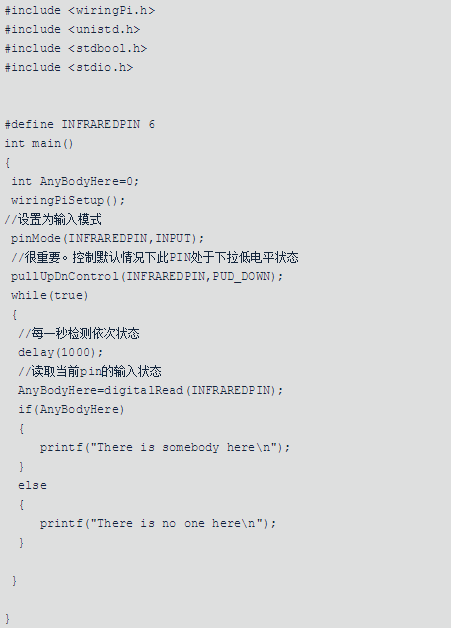
The detection code is quite simple: 
We will slightly modify it. When a human is detected, we will use the beep function from section five to perform the alarm operation. Here, we choose to use H mode for continuous sensing; upon detection, we will use beep to sound the alarm. This way, we have simply implemented an automatic alarm after human detection.