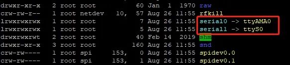
From the relevant information about the Raspberry Pi, we can see that there are two serial ports available: one is the hardware serial port (/dev/ttyAMA0), and the other is the mini serial port (/dev/ttyS0). The hardware serial port has a separate baud rate clock source, providing better performance and stability; the mini serial port has simpler functionality, lower stability, and its baud rate is provided by the CPU core clock, thus affected by the core clock.
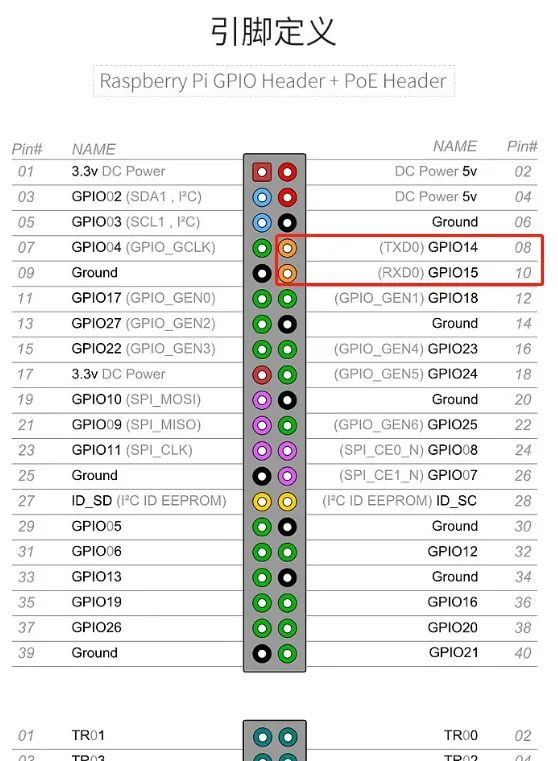
The Raspberry Pi (3rd/4th generation) has an onboard Bluetooth module, and the default hardware serial port is allocated for the Bluetooth module, while the less efficient mini serial port is allocated for GPIO serial TXD0 and RXD0.
Run the following command to view the default serial port allocation:
ls /dev -al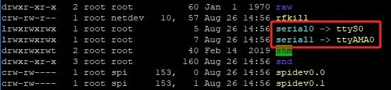
Since the hardware serial port is allocated for the onboard Bluetooth, we need to free it and set the hardware serial port to be allocated for the GPIO serial.
1. After SSH logging into the Raspberry Pi system
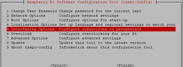
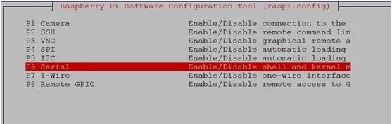
sudo raspi-configEnter the Raspberry Pi system configuration interface, and select the fifth option, Interfacing Options:
Enter P6 Serial
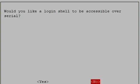
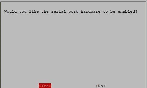
Select to disable the serial login feature and enable the hardware serial debugging feature:
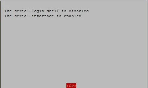
After completion, the following interface will be prompted, press OK.
Exit the raspi-config settings and restart the Raspberry Pi as prompted.
2. Set the hardware serial port to GPIO serial
Edit the config.txt file in the /boot directory
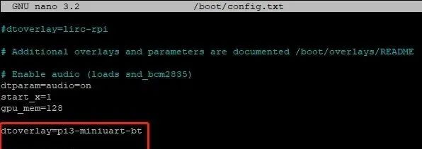
sudo nano /boot/config.txtAdd the following two lines to the end:
dtoverlay=pi3-miniuart-bt
force_turbo=1
The modified file is shown in the image below
Save: Ctrl+O, Exit Ctrl+X.
Restart the Raspberry Pi
sudo rebootAfter restarting the Raspberry Pi, input ls /dev -al again, and you will see that the two serial ports have swapped positions:
3. Testing with Minicom Serial Assistant
Install Minicom
sudo apt-get install minicomAfter installation, start Minicom
minicom -D /dev/ttyAMA0 -b 9600Where -D specifies the serial port **/dev/ttyAMA0**, and -b sets the baud rate to 9600. This parameter can be omitted as the default is 115200.
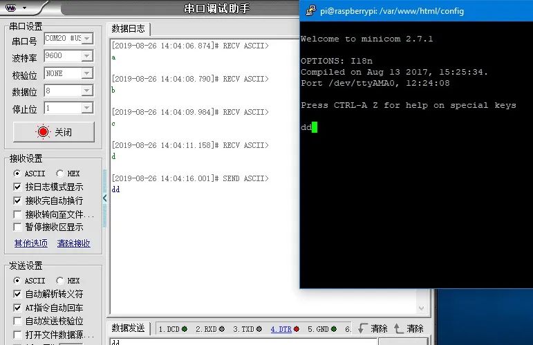
Once the serial port is opened, data can be transmitted via the USB to TTL module.
Exiting Minicom is somewhat complicated; follow the prompts: first press Ctrl+A, then press Z to bring up the following menu,
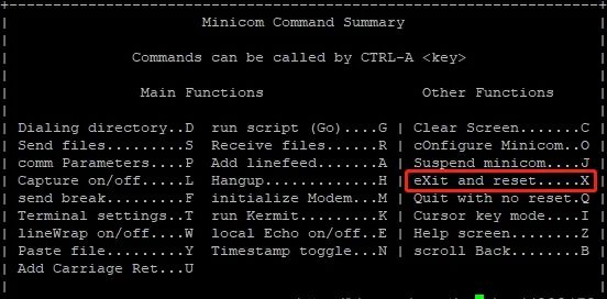
Then press X, and finally select YES and press Enter to confirm.
The connection of the USB to TTL module is shown in the figure below:
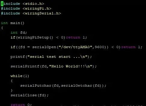
4. C Language Test Code, Print Hello World
The code is as follows:
#include <stdio.h>
#include <wiringPi.h>
#include <wiringSerial.h>
int main(){    int fd;    if(wiringPiSetup() < 0)return 1;
    if((fd = serialOpen("/dev/ttyAMA0",9600)) < 0)return 1;
    printf("serial test start ...\n");
    serialPrintf(fd,"Hello World!!!\n");
    while(1)    {        serialPutchar(fd,serialGetchar(fd));    }    serialClose(fd);
    return 0;}
Create a file named testCom.c and copy the above code into it
nano testCom.cSave: Ctrl+O, Exit Ctrl+X.
Use the gcc compiler to compile the program:
gcc testCom.c -o test -lwiringPiRun the program
./test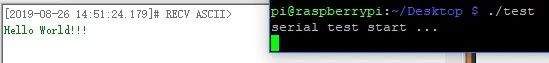
Data can also be sent to the Raspberry Pi via the serial port, which will directly return to the serial port display.
Note: If there is garbled output, please check the baud rate, which needs to be set to 9600, corresponding to the above code.
“MuJoCo Robot Impedance Control Simulation“
This course is based onDeepMind‘s open-source robot simulation platformMuJoCo, developing and implementing two impedance controllers for theUR5robot, and using the controllers for point impedance characteristics and trajectory tracking experiments.

(Scan the QR code to view course details)